Oscar
-
Posts
2,485 -
Joined
-
Last visited
-
Days Won
67
Oscar's Achievements
Well-known member (3/3)
-
The 1940 Canberra air disaster that changed history
Oscar replied to Admin's topic in Aircraft Incidents and Accidents
From the autobiography of Dick Kingsland, DFC, 'Into the Midst of Things': Another interesting character in my block was Bob Hitchcock, whose dangerously poor flying capacity became patently obvious to everyone on our course. History shows that he was not taken off flying, and he was the captain of the aircraft which crashed while on approach for landing at Canberra in August 1940, killing all on board, including the Hon. J.V. Fairbairn, the Minister for Air and Civil Aviation, after whom the airport was subsequently named. Anybody who knew Sir Richard Kingsland, knew that he was honest to a fault and absolutely NOT the person to harbour a grudge; therefore I believe his comments should be taken as reasonable. -
I may be wrong here - Bruce will, I would hope, correct me if I am - but the actual rudder appears to me to be unchanged. That means that the CONTROL surface area and reaction loading to the fuselage remains the same (and the fin/fuselage connection loads, which for reasons I do not care to enter, need to be considered - I have discussed those concerns privately with Bruce) remain unchanged. This is a good thing from a structural POV; start changing the loads into an airframe and you very, very much need an experienced Aero Engineer to tell you if you are acting wisely or putting a round into the chamber of a revolver you will be placing at your temple and pulling the trigger.. The increased area of the FIN will increase the horizontal stability relative to the apparent wind across its surface - much as larger feathers make an arrow fly straighter relative to the wind. That may - or may not be, depending upon the cross-wind component to be battled for desired heading maintenance - useful. I would expect that for most conditions, a bit more horizontal stability would make life easier in cruise. Where there is a need for more rudder power, however - this mod. seems to me to offer little if anything. I do NOT mean that to be pejorative - about 95% or more, I suspect, of power flying is A-to-B straight line stuff where stability = comfortable, low-energy flying. Glider pilots (of whom Bruce is one) enjoy the benefits of a high level of control effectiveness. Rudder power is essential for anti-spin-entry control in thermalling; serious levels of side-slip control is useful for outlandings in tight conditions. I would expect that the mod. Bruce has made, will make general flying in his wee Jabby somewhat more comfortable, at the possible expense of an almost imperceptible reduction in absolute rudder authority for cross-wind conditions. Given that balancing direction in a side-slip between rudder and aileron control becomes increasingly a tap-dance as one gets closer to the ground, I personally reckon Bruce's mod. is likely to be time-effective as a 'make my trips more enjoyable'.. That DOES NOT mean that simply taking a trowel and a heap of foam and 'glass to your LSA55, is desirable...or necessarily, safe. A careful reading of the entirety of this thread should be your first recourse.
-
Small aircraft crashworthiness
Oscar replied to Dafydd Llewellyn's topic in AUS/NZ General Discussion
Of course a steel triangulated space-frame absorbs energy. If it didn't, every such structure would simply fall apart when subject to load. This is akin to saying that water is wet. It is the rate of rise of the member fail-point (in part) that impacts the human frame. It is no damn use to you if the stresses upon (for example) your spine being transmitted from the space-frame relieve just AFTER your spine has broken. A tubular steel structure CAN be designed to fail - and in a complex structure, CAN be designed to fail progressively - within the envelope of human tolerance. FAA compliant crash-worthy seats are (often) good examples of this. FEA has improved the ability of designers to create progressively deformible structures vastly less costly than the old 'break-it-and-see' regime. However, even with CNC-controlled welding of 4130, it is (in my opinion) likely you would need to do a full heat-treatment of the completed structure to ensure there are no overloaded junctions etc. May I point you to the commentray regarding Ducati motoGp bikes in the era 2007 - 2009: $m ultimate racing machines with a welded space-frame. According to the most successful rider ever for Ducati, these 'varied with every frame' in characteristics. I have built racing cars from tube-frame structure - I DO like it as a medium. BUT, it isn't the answer to the Maiden's Prayer, it is just ONE way of getting there. Of all the high-performance devices now in use, I believe that a space-frame is only used by KTM on their motoGp bikes - everything else has gone to either composites or forged/cnc-machined alloy beam construction. Jabirus are possibly unique in the ultralight market, in being built from low-tech ( ambient-cure resin and glass reinforcement) materials, which by their nature have considerable elasticity and a slow rising-rate of resistance to load. It is no aberration that the fatality and injury rate for Jabirus is remarkable. -
Possibly, the very large number of SR-22s that have crashed has finally impinged onto the media consciousness?
-
Here's a few observations from someone who has watched engine developments closely over many years: 1): When the adjectives/adverbs in the commentary ( 'revolutionary', 'greatest', 'unmatched') etc. seem to outnumber the actual fact-bearing words used, it is BS 2) When the depiction is purely derived from CAD, it is BS 3) When there is no reliable evidence of results from tests undertaken by a reputable third-party testing organisation, it is BS 4) if the engine web-site contains any information as to how to invest in this miracle, it is a scam.
-
You always have ONE in clean air for spin recovery???
-
Red: a Glider IS an aircraft... However, not to be an irascible pedant for too long.. I don't know. BUT, military gliders (mostly troop carriers, but also for heavy weapons transport), were used quite a lot in WWII. Military glider - Wikipedia . They were not designed to soar, but to glide to land following release from a tow aircraft. The Me 321 was the mother of all. messerschmitt me 321 - Google Search: And it spawned the 'Gigant' the world's most fugly but imposing motor-glider: messerschmitt gigant - Google Search:
-
May I be allowed a little romanticism here? Diverging somewhat from the main topic of the thread, but some might find it interesting. Blaniks were the most produced glider, ever. They were roughly speaking, the C172 of the Glider world. But when they were all grounded following the Red Bull Aerobatics Team crash in 2010, the only ones cleared for flying - anywhere in the world - were the Llewellyn-modded ones. He identified the mainspar and tail structural problems and designed fixes for them, in 1978 - . something like 32 years before the failure that grounded all the rest. They were intended as the initial trainer for all Russian airforce pilots. I did most of my training on Blaniks, and they are a delight to fly - though not high-performance, they just do what you ask of them, a bit like a classical English Butler... no matter how ham-fisted you may be, they never, ever, bite you back. A Gentleman's carriage. I was a founding member of the ANU Gliding Club. We had a Blanik and a motor-Falke ( a flying barge with self-launching capability). Someone in the ANU club had found that the guy who was the Blanik test pilot, and then became the chief instructor for the entire Russian airforce initial training, was a resident in Canberra, and persuaded him to join us. I cannot - damn it - remember his full name, but memory suggests his first name was Jan. He had something like 12,000+ hours on Blaniks alone! We persuaded him to become an Instructor for us. But he had to be checked out by the NSW head of Operations ( I think that was his title..) - Werner Geissler. I knew Werner ( a bloody good pilot..) a bit, due to family connections with GFA hierarchy. I was at our field (Currendooley, on the side of Lake George, now a huge wind farm) the day Jan came out to be checked out by Werner. When that flight was over, I wandered over to Werner and quietly asked him: 'Is he any good?' Werner just said: 'Are you kidding? There is nobody in the world could be better'. Werner signed him out on the spot; I flew with Jan later that day, in the motor-Falke, and I cannot adequately describe the feeling that one was in the hands of a god... the best I could get to describing it, is that where any mortal would react maybe to within 10% of the necessary response to even the slightest change in flight parameters, he seemed to be ahead of them before they happened and his reactions were 99.99% exactly right. The nearest thing I can think of as an analogy, would be watching a Snooker master, executing a shot that not only potted the ball, but set up the next shot perfectly. But - the funniest thing on that day was not the flying. Jan was a very, very reserved person, but it turned out that both he and Werner had been in the Luftwaffe in WWII, and they got chatting (in English) about their experiences of flying Me109's on raids on London, shooting up the Thames. Our ANU club President was an Englishman, in London in WWII, and you could see him visibly steaming as he also listened to their conversation.. but to give him his due, he recognised that Jan was an invaluable resource to our club, and bit his tongue.
-
A guttering candle stub? - Luxury. We had a drawing of a candle, which all 24 of us had to share, and it didn't work after dark.
-
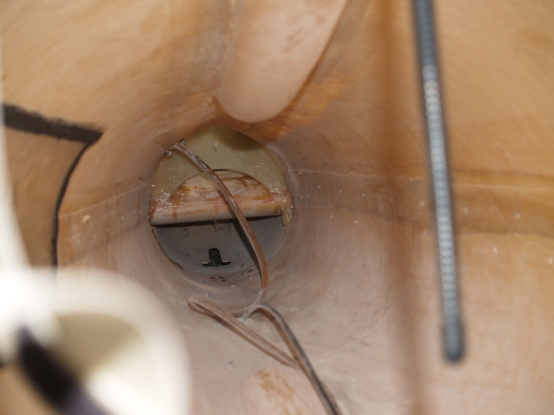
Bruce: what we did was a 'limit load' test, as advised by Alan Kerr. As I understand it, that is the expected 'ultimate' load that can be applied in flight due to aerodynamic pressure, it's not a structural 'fail' load, but I assume that Alan recommended it because it's the practical load for flight condition. Pretty obviously, you wouldn't want to test for structural fail, i.e. take your mods to the breaking point and then having to rebuild the whole fin.. I agree - a limit-load test is sufficient to guarantee that the fin will take whatever the flight loads can impose. There are a few other things to consider, however, before you could be entirely sure that the overall changes you have made are not going to cause problems, I will mention some of those further below. In order to do a limit-load test, it takes quite a bit of sophisticated setting-up. If you go to the Jabiru site and look at the videos they have there on testing, you will see that they have a rather massive jig, with calibrated hydraulic rams providing the force inputs. We made up a 'backyard' equivalent that was good enough.. but it wasn't particularly 'unsophisticated' in regard to replicating the actual loads throughout the fuselage structure, even though it was as rough as guts to look at. By the nature of a Jab. structure, the reaction of the load on the fin is taken out by the entire bond between the fin attachment and the tailcone, and that, in turn, ends up being taken out at the bulkhead behind the seats that 'circles' the aft wing root and the lift-spar attachment points. The entire tail-cone fuselage structure is - obviously - a monocoque structure from there aft, and is subject to twist induced by the fin. So, your 'limit-load' test needs to be applied appropriately. Rather conveniently ( but not by happy accident, but by intelligent design), the u/c main leg attachment points are centred on that main bulkhead. So, if you make a rigid jig that picks up off those main u/c leg attachments, you have part of the limit-load test apparatus sorted. You can't just apply a sideways 'push' to the fin if you are using the u/c to react that out - because the spring in the u/c legs will reduce the load applied to the fin being reacted out on the fin/tailcone join. In regard to the actual aerodynamic load on the fin needing to be taken out by the fin/tailcone join structure - obviously, that load is a product of fin area and distance from the join. I assume (in the absence of being an engineer), that it is possible to calculate using FEA/fluid dynamics, a centre of pressure for the fin + rudder area. I have no idea of how to go about this, you need an Alan Kerr, or someone with his sort of skills to tell you! I've done it - crudely - for sails, but aircraft tail-feathers operate in a complex airflow situation due to downwash from the wings, just for a start. This is the sort of thing that is the reason why people like Alan, Bill Whitney, Dafydd Llewellyn, Graeme Swanell, Bob Scott etc. are used by manufacturers... and the reason that actual testing is done, is to validate their calculations.. However, it gets more complicated. Aircraft structures (mostly) bend under load, and that introduces additional considerations where control surfaces are concerned. Have you ever wondered why the Jab. instructions for the lift-strut attachment bolts have a placarded instruction that they are NOT to be tightened? It is because the load on the lift-struts MUST be taken out concentrically throughout the strut - or it will fail in compression (negative-G). You will notice from my earlier post, a picture of the load-test on the fin on our aircraft. The apparatus pictured is a 'whiffle-tree' - a way to introduce a point-loading distributed across a beam that reproduces the force of a varying actual load condition. As an old (no disrespect) glider person, you have probably seen piccies of wing tests, with many bags of sand distributed across the wing, stacked in a definite pattern. That load AND its distribution is not accidental - it is calculated to reproduce flight condition. Where you have a conjunction of a beam ( as in a wing, or fin, or horizontal stabiliser) and a moving control surface (aileron, rudder, elevator), bending can introduce problems. This is NOT something to be ignored.. Example: (somewhat ironically, since the engineers involved were also those involved in the development of your aircraft - and mine..) - for the development and certification of the Skyfox from the original Kitfox. Dafydd Llewellyn was the test pilot (yes, some aero-engineers actually CAN fly competently, to CASA test-pilot standard!). Alan was the structural engineer. Dafydd found that under heavy-load turns (rate 2 or more),. the ailerons completely bound up solid. (A test-pilot's life can be interesting.. he also had several instances of severe aileron flutter, which were a tad disconcerting. He does all his test flying wearing a parachute, which I think is standard practice). Alan designed the solution. If you watch the Jabiru test videos, you will note that Alan tests the control surface freedom under full test load bending. Guess why he does this! From memory, the Jab. video shows him testing the elevator as the load is progressively applied. The Jab. rudder is - I am sure you will have noticed - a quite delicate and light structure. And the aft-end of the fin, to which the rudder hinges bolt, is not exactly excessive in 'glass thickness. That BOTH are 'fit for purpose' as designed is obvious. I don't know for sure but I strongly suspect they are designed as a pair for the job (Alan again could guide you here). In a worst-case scenario, if you were to add height to the existing rudder, cut the fin to suit, probably space-out the hinges to more equitably distribute the load - you MIGHT get unanticipated bending components that cause the rudder to bind up. Yes, I am probably being somewhat ultra-cautious here, but I would want to be assured by ground-testing before I took it flying. The points I am trying to make here, are absolutely NOT that one shouldn't make mods. - but that IF you do, then don't rely on 'what looks OK' is sufficient guarantee it will work. You need - in my opinion - to test adequately and comprehensively, that it does. One way, is to take the thing up to say 5K feet, and wring it out to the limits.. but hanging in the silk watching it spiral down below you, is probably not a wonderful reward for a lot of work.
-
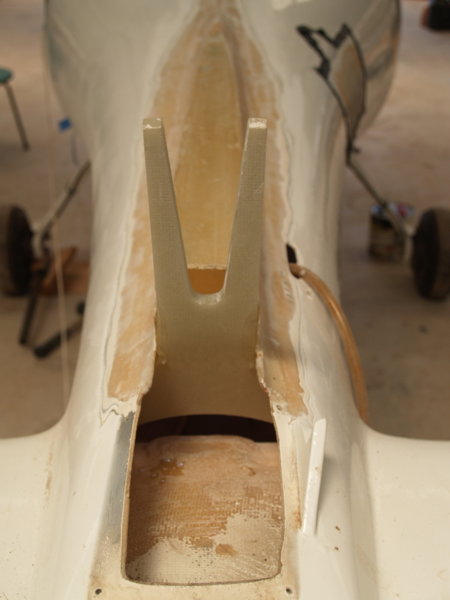
There is a lot of opinion here, but not a lot of it is based on a knowledge of the actual Jab. structure. There is ONE expert in Australia on this, for the LSA55: Alan Kerr. He knows more even than Rod Stiff, since Alan did the structural validation of every Jab. from (I think) the LSA55 and derivative models through to at least the J160. I don't wish to be a 'smartarse' here - but Alan Kerr did the justification for certification / certifying tests on all of those. He has, in his files, the details of the loads, the test procedure, the results. If you look at the test videos on the Jab. website, that quiet, curly-haired guy checking things out - that's Alan. Alan is a world-recognised expert; he's done fin upgrade mods that keep F-16s flying, mainspar repairs of Globemasters ( from memory) to keep them in the air. He is probably the world's premier expert on the use of boron-fibre in ultra-high-stress area repair. With respect o the ideas being passed around re extending the rudder on an LSA55 fin... First of all, you need to understand that the fin only has a 'mainspar' that extends to the top of the standard rudder. That mainspar transfers the loads of the three rudder hinges between the two skins. IF you make a larger cut-out to accommodate a vertically-enhanced rudder, you cannot change the hinge positions. Son any vertical extension - let alone chopping out an area of the top of the fin to have an aerodynamically-balanced rudder a la J160, would introduce a considerable area of completely unsupported fin which WILL twist under load. To mitigate that, you would need to add an internal structure to the existing fin moulding of a mainspar extension and at least a rib at the point of a relocated top hinge for the rudder. Can be done BUT you'd need to be bloody good at your glass-work. And preparation of the inside of the existing fin moulding would be a bitch; at a minimum, sodium-blasting of the inside fin surface. Then, insertion of the rib and the mainspar extension... do you have keyhole-surgery expertise? It's about what you need for that job... been there.. Now, assuming you have all that done... a taller rudder introduces more load on the whole fin (that has to react that load out to the fuselage tailcone). I have done the job of adding an enlarged fin/rudder combination to an LSA55 model Jab. (see my post #14 above). ONE of the major differences in basic structural differences between an LSA55 and a J120 - let alone a J160, with the aerodynamically-balanced rudder - is the structure required to react out the increased load on the fin into the tailcone. On the LSA55, the fin is simply glued onto the 'saddle' structure on the tailcone. That works, for that fin and rudder combination. On the J120, there is an additional and quite significant carry-through member between the fin 'mainspar' and the tailcone to handle the loads. This is what it looks like, when grafted into an LSA55: That was NOT an easy job... and the only way we could do it was because we had the fuselage in a virtual 'rotisserie' cradle. ANYTHING, can be done... but to BE done safely and effectively, you need to know all the ins-and-outs. If you are prepared to risk your life to 'that looks about right, hand me the angle grinder'.. good luck.

-
A Tale of Two Airships - R-100 & R-101
Oscar replied to Phil Perry's topic in UK/Europe General Discussion
Not to pre-empt the next chapter to come... but with reference to my earlier comment that the tail-surfaces are very ineffective at providing control in the usual sense we think about them: (from the Wiki article: R101 - Wikipedia ): Flying around 800 ft (240 m) above the ground, it passed over Alexandra Palace before changing course slightly at the landmark clock tower of the Metropolitan Cattle Market north of Islington, and thence over Shoreditch to cross the Thames in the vicinity of the Isle of Dogs, passing over the Royal Naval College at Greenwich at 20:28. The airship’s progress, flying with her nose pointing some 30 degrees to the right of its track, was observed by many who braved the rain to watch it pass overhead.[68] That is why I used the term 'horizontal control' rather than 'yaw'. The damn things would point mostly according to the side area exposed to the prevailing wind on track. Anybody who has ploughed a muddy field in a 2WD tractor will know that the steering is useless, you dance the independent brakes to maintain directional control. Possibly similar, is sailing a 'Colin Archer' style yacht - long keel with a small rudder - upwind, where you have to play the main and jib to vary the position of the centre of pressure of the combined sail area vs. the centre of lateral resistance of the underwater profile. You can flog the tiller all you want and the thing will take no bloody notice.. (possibly why the aphorism 'Gentlemen don't sail upwind' started..) -
A Tale of Two Airships - R-100 & R-101
Oscar replied to Phil Perry's topic in UK/Europe General Discussion
From indistinct memory, (I don't have Leasor's book on hand), a test prop on the R101 test engine broke loose, due to the huge torque pulses of the diesel engine, broke through its 'chain mail' safety cage and the hangar wall, and was found some vast distance away - perhaps as far as a half-mile, though that could be hugely incorrect. The engines on the R101, for maneouvering, had to be stopped and then re-started in reverse if they needed reverse thrust for docking etc. IIRC, each engine had a small 'starter' engine with a gearbox to spin the diesel up in the desired direction, and that required a crew member to climb down into the engine pod (via an exposed ladder!) and throw the gearbox on the starting engine. The starter engines were petrol-powered (thus negating somewhat the requirement for no petrol aboard!) but I think their petrol was stored in the engine pods themselves - which ran at very high temps in continual operation. Due to aerodynamic effects, the 'tail-fin' control surfaces on all the rigid airships, were very, very ineffective. Due to the HUGE hole in the air these things created, I believe that even at full-speed - maybe 65-70 knots - you could stand on the tail fins in at most a 'gentle breeze'. I THINK that the R101 had an 'observation deck' on top, where one could promenade probably without losing your hat! A lot of the vertical attitude control was by varying power / dumping hydrogen from the appropriate multiple bags spread along the interior / dumping ballast from the multiple containers. Either of which options immediately reduced the surplus of control options. Horizontal control by varying engine power. The VAST surface area contributed problems of its own. Static electricity build-up was so huge that they needed to drop an earthing cable before it would be safe for the ground handlers to grasp the mooring cables. I seem to remember a segment in the Leasor story, where one of the senior engineers tackled a ground handler to the dirt as he rushed forward to grab his cable, thus saving his life. ( I think the Hindenburg disaster was attributed to static igniting the Hydrogen, but I may well be wrong there.) The saga of the R101 maiden flight and crash is a terrifying read. It was basically out-of-control and fated to crash mid-way across the Channel, having failed monumentally to even gain decent flying altitude, in atrocious weather. Plus, the covering skin - which had had to be entirely replaced - was suspect due to the doping methodology used, and started to tear apart somewhere over the Channel, dumping large quantities of water inside. The R101 was a dead-dirigible-walking before it unclipped from its mooring mast. In a small, personal aside - but to perhaps give an idea of the size of the damn things - when I was at Cardington, I was chatting with the manager of the facility. He told me that they'd had real problems with the environmental control of the hangar - it has (or at least, then had) a largely glass roof and is perhaps the world's biggest 'glass-house', with summer temps going up to ridiculous levels. The safety aspect of having anybody working on large sheets of glass that were over 50 years old, had stumped them - until someone came up with the bright idea of using a crop-spraying helicopter as a spray-gun to coat them with white paint. Again - to give a sense of scale: the R101 was only about 100 feet shorter than the Titanic.. -
A Tale of Two Airships - R-100 & R-101
Oscar replied to Phil Perry's topic in UK/Europe General Discussion
And there is a lot of good background stuff on the R100/R101 story - particularly the R101 crash - in James Leasor's 'The Millionth Chance'. The R101 project was an unmitigated disaster all the way through a combination of bureaucracy, politics and management, while the R100 was just about exactly the opposite. The scale of these things is just immense - I've been in the Cardington hangar, and they (seriously!) get cloud forming under the roof in some conditions!l -
The owners buy the dream. Then, the nightmare begins.