Dafydd Llewellyn
-
Posts
1,513 -
Joined
-
Last visited
-
Days Won
43
Content Type
Profiles
Forums
Gallery
Downloads
Blogs
Events
Store
Aircraft
Resources
Tutorials
Articles
Classifieds
Movies
Books
Community Map
Quizzes
Videos Directory
Everything posted by Dafydd Llewellyn
-
J120 drops oil @ YCRG. Very lucky timing
Dafydd Llewellyn replied to rrogerramjet's topic in Aircraft Incidents and Accidents
Could we PLEASE have the bloody FACTS on the engine that was the original subject of this stupid thread? In clear, plain English? 1. What was it that actually failed? Was it a through-bolt or was it a head bolt? 2. If it was a through bolt, which version was it? 3. How many hours did it have on the bolt that actually failed? 4. When was the torque last checked on the bolt concerned? Those questions at least should be able to be answered from the engine log book. There are a lot of other questions that would only be answered from a bulk strip. -
Bolly Prop 68"on a 912ULS in a Tecnam Sierra
Dafydd Llewellyn replied to DonRamsay's topic in Engines and Props
Well, that's been my experience with little aeroplanes, and engines below about 250 horsepower. Also, from a noise point of view, if there's any acoustic effect due to interaction between the propeller and the aeroplane, the more the blades, the higher the pitch of the noise - which makes it much more annoying. This can be important, if it makes you aircraft more noticeable; it becomes "that *!##" aeroplane" - and when that happens, the local complainers really get going. -
Do vortex generators really work.
Dafydd Llewellyn replied to stevron's topic in AUS/NZ General Discussion
Yep; silly, ain't it? Oddly, I found I could consistently do shorter landings in a Beech V35B (78 knots over the fence) than I could in my Cherokee 140 (60 knots over the fence) simply because you could always pick exactly when the Bonanza would stop flying, whereas the Cherokee was inconsistent. May have been the braking effect of the CS prop in fine pitch, but it showed me that controllability was at least as important as a slow approach speed. I've not flown a D9, only a flapped D11 (once), but I expect they're not to dissimilar in general behaviour - and it felt pretty good in that department. The correct use of VGs does help the controllability - that's its principal advantage, in my view. -
Bolly Prop 68"on a 912ULS in a Tecnam Sierra
Dafydd Llewellyn replied to DonRamsay's topic in Engines and Props
The normal certification requirements are: (a) The propeller must not allow the engine to overspeed at full throttle at any speed up to & including the speed for best rate of climb (Vy); (b) The propeller must not cause the engine to overspeed in a dive with the throttle shut at any speed up to & including Vne. I've always thought these to be pretty much common sense. That said, I assume the propeller has three blades? If so, it may have a larger-than-optimum "activity factor" (the propeller equivalent of wing area) for the engine. The best propeller efficiency normally occurs when the local blade angle-of-attack is at the optimum angle for the blade airfoil - which is often in the vicinity of ten degrees (relative to the helix angle of the blade at the flight speed concerned, at around 75% radius). Too much blade area will require the pitch to be fined-off to allow the propeller to rev., and if that results in too low a blade angle of attack, the propeller efficiency will suffer. I once tested a Murphy Renegade to try to discover why it was climbing so poorly; it had a 3-blade ground-adjustable prop; to get the engine to work in its correct RPM range, the blade angle at 70% had to be set as low as 13 degrees. In that case, going back to two blades gave a marked improvement. 3-bladers seem to be "fashionable"; but this does not necesarily mean they are better. -
There's a reason why aircraft noise is not too much of a problem; see http://www.airservicesaustralia.com/services/aircraft-noise-certification/ - Recreational aircraft are NOT in general, exempt from these regulations. Ignorance of the law is no excuse.
-
Do vortex generators really work.
Dafydd Llewellyn replied to stevron's topic in AUS/NZ General Discussion
I think you will find that they'll work just as well that bit further out; the main thing is that the tailplane is wholly in the wake of the part of the wing between the fences. You may lose a couple of tenths of a knot of the reduced stall speed, but the spin-resistance will still work. It's not critical that the vortices hit the tailplane. -
If wishes were horses, we'd all ride . . . My STC has already covered the CASA approval aspect. That's wot STCs are for.
-
Firstly, I said "hone", not "Rebore" - there's a difference, you know. The hone finish is critical for oil retention. Secondly, I was talking about CAMIT barrels, not Jabiru barrels. Also, what I said about process control holds; putting a steel barrel into an electroplating or stripping bath? Ever hear of hydrogen embrittlement? CAMIT works under a CASA Production Certificate; we're not talking about motorcycle engines, here.
-
The "unless this is done by other means" allows scope for the airframe manufacturer to embark on a research project to evolve an alternative means, and prove to the satisfaction of the certificating authority that it works. Fine, if you happen to be a State-funded aeronautical research organisation; might get a Master's paper out of it - maybe. However, this is a case where the design standard provides a means of compliance that the manufacturer can apply without having to set his program back by months and maybe a hundred thousand dollars, simply by having an exhaust muff and a simple valve operated by a bicycle handbrake cable. It relies on the experimental fact that a 50C rise in temperature upstream of the carburettor, will give a 15C rise in the temperature in the carbie throat downstream of where the fuel is admitted. Pulling full carbie heat does NOT raise the temperature of the air reaching the cylinders by 50C; the rise is around 15C, due to the latent heat of vaporisation of the fuel. Provided the carburettor bowl venting is done correctly, there will be almost no perceptible power loss (This can be observed in the Gazelle; it was one of the few things that were done - eventually - very well, in that aircraft). The route to less costly certification is to have a greater proportion of the design standard codified in this sort of manner. CAR 3 used to be largely codified; unfortunately, Ralph Nader pointed out that government should legislate for the end, rather than for the means. That resulted in FAR 23 being written to a far greater degree in the style of the required end result, without specifying how that could be achieved. Fortunately, the FAA then set about writing a whole library of Advisory Circulars that specify "acceptable means of compliance". Almost all the recreational aircraft standards that have appeared since, are watered-down versions of FAR 23 - usually with the same numbering system - but without the Advisory Circulars. So much for "progress". So, nowadays, one has to look up the requirement, and then go hunting for the current version of the AC that addresses it. If you use the means of compliance given in the AC, the certificating authority will usually rubber-stamp it. If you choose to invent a new way, this brings the certification process to a dead stop whilst the certificating authority researches the matter and satisfies itself that your method is acceptable. Meanwhile, the Applicant's finances are steadily running out. Being clever is a real good way to go broke, trying to certificate an aeronautical product. So, how smart is it to muck about with electric heating pads on the induction system? The gain is likely to be very small, and the overall cost, staggering. If you want to play about with such alternative methods on your homebuilt, fine. But if you just want a safe aircraft to fly, simply follow what is already a proven means.
-
Horse ****. Firstly, the provision of induction heating is NOT a requirement for the engine manufacturer; go look at JAR 22H. It's a requirement for the AIRFRAME manufacturer. And there are no ifs or buts about it. It's in FAR 23.1093: § 23.1093 Induction system icing protection. (a) Reciprocating engines. Each reciprocating engine air induction system must have means to prevent and eliminate icing. Unless this is done by other means, it must be shown that, in air free of visible moisture at a temperature of 30 °F.— (1) Each airplane with sea level engines using conventional venturi carburetors has a preheater that can provide a heat rise of 90 °F. with the engines at 75 percent of maximum continuous power; (2) Each airplane with altitude engines using conventional venturi carburetors has a preheater that can provide a heat rise of 120 °F. with the engines at 75 percent of maximum continuous power; (3) Each airplane with altitude engines using fuel metering device tending to prevent icing has a preheater that, with the engines at 60 percent of maximum continuous power, can provide a heat rise of— (i) 100 °F.; or (ii) 40 °F., if a fluid deicing system meeting the requirements of §§23.1095 through 23.1099 is installed; (4) Each airplane with sea level engine(s) using fuel metering device tending to prevent icing has a sheltered alternate source of air with a preheat of not less than 60 °F with the engines at 75 percent of maximum continuous power; (5) Each airplane with sea level or altitude engine(s) using fuel injection systems having metering components on which impact ice may accumulate has a preheater capable of providing a heat rise of 75 °F when the engine is operating at 75 percent of its maximum continuous power; and (6) Each airplane with sea level or altitude engine(s) using fuel injection systems not having fuel metering components projecting into the airstream on which ice may form, and introducing fuel into the air induction system downstream of any components or other obstruction on which ice produced by fuel evaporation may form, has a sheltered alternate source of air with a preheat of not less than 60 °F with the engines at 75 percent of its maximum continuous power. (b) Turbine engines. (1) Each turbine engine and its air inlet system must operate throughout the flight power range of the engine (including idling), without the accumulation of ice on engine or inlet system components that would adversely affect engine operation or cause a serious loss of power or thrust— (i) Under the icing conditions specified in appendix C of part 25 of this chapter; and (ii) In snow, both falling and blowing, within the limitations established for the airplane for such operation. (2) Each turbine engine must idle for 30 minutes on the ground, with the air bleed available for engine icing protection at its critical condition, without adverse effect, in an atmosphere that is at a temperature between 15° and 30 °F (between −9° and −1 °C) and has a liquid water content not less than 0.3 grams per cubic meter in the form of drops having a mean effective diameter not less than 20 microns, followed by momentary operation at takeoff power or thrust. During the 30 minutes of idle operation, the engine may be run up periodically to a moderate power or thrust setting in a manner acceptable to the Administrator. © Reciprocating engines with Superchargers. For airplanes with reciprocating engines having superchargers to pressurize the air before it enters the fuel metering device, the heat rise in the air caused by that supercharging at any altitude may be utilized in determining compliance with paragraph (a) of this section if the heat rise utilized is that which will be available, automatically, for the applicable altitudes and operating condition because of supercharging. [Amdt. 23-7, 34 FR 13095, Aug. 13, 1969, as amended by Amdt. 23–15, 39 FR 35460, Oct. 1, 1974; Amdt. 23–17, 41 FR 55465, Dec. 20, 1976; Amdt. 23–18, 42 FR 15041, Mar. 17, 1977; Amdt. 23–29, 49 FR 6847, Feb. 23, 1984; Amdt. 23–43, 58 FR 18973, Apr. 9, 1993; Amdt. 23–51, 61 FR 5137, Feb. 9, 1996] You will find a similar requirement - somewhat watered down in some cases - in all aircraft certification requirements. Of course, with a homebuilt experimental, you can ignore this - which in my books should qualify you as a Darwin Award candidate.
-
Every additional process in the manufacture of (especially) a type-certificated product, involves an additional set of process controls, with audit, paper trail etc. A process like Nikasil is likely to involve a complete plant by itself. This would double the cost of the engine, for not much real benefit. Also, you cannot hone-out a Nikasik barrel to the next oversize, as you can with a plain steel barrel. The barrels are carrying the tensile load from the combustion pressure on the head, which has to be carried all the way down to the main bearing caps. Steel barrels will do that, aluminium ones won't; they need the head hold-down bolts to go all the way to the crankcase - which fouls up the finning and also the airflow through the fins. Lycoming put plain steel barrels in the 0-320-E2A in the PA28-140; I had one. I made a point of doing a circuit or two in it once a week. It held full compression all the way to 2000 hours. Plain steel barrels are much less prone to glazing than nitrided ones. In short, plain steel barrels are a damn good practical compromise. Adding an inhibiting squirt to them sounds to me like a really smart solution. Zer Chermans do not go in for that sort of thing; they use unobtainium, but it's not so practical when it comes to overhaul time.
-
They run under the clause that allows them to be used for display purposes. You can't use one as a general hack under that clause. The J5G is a certificated aircraft, and with the o-360 in it under an STC, could (if anybody wanted to) be used for a commercial purpose. But it makes a very useful four-seat private aircraft, if its C of A remains in force.
-
Erhm - the Lyc 0-360-A already has a dynafocal mount. Also, you had better look up CASA Advisory Circular 21.10 (look on the CASA website under CARS 1998, CASR Part 21) for the constraints that apply to using a factory-built aircraft for an experimental purpose. It's not as straightforward as you seem to imagine.
-
Thanks, Nev - however the STC covers Lyc 0-360-A series only. I need to check, but I think 0-360-A1A or 0-360-A4A only
-
Do vortex generators really work.
Dafydd Llewellyn replied to stevron's topic in AUS/NZ General Discussion
Fair comment - but the absence of mention in crash reports may well be due to the fact that the possible effects are not generally well understood - and also to the fact that ATSB does not investigate crashes of experimental aircraft. -
Do vortex generators really work.
Dafydd Llewellyn replied to stevron's topic in AUS/NZ General Discussion
Well, if it's an LSA factory-built aircraft, one cannot go bunging VGs on it without the manufacturer's consent. If it's a Type-certificated aircraft, you don't need the manufacturer's consent, but you do have to do it in accordance with approved data - which could be an STC or a Part 21M approval. If it's a homebuilt or an experimental aircraft, you can do what you like, subject to the rules re operation in a designated test area - but unless you don't mind possible unpleasant surprises, it would be at least prudent to know enough about the aerodynamic design of the aircraft to have some realistic idea of the likely effects. Having said that, I'd expect the Seeker-type solution to work pretty much the same on most high-wing aircraft that do not already have leading-edge devices, except possibly those with NACA five-digit wing airfoil sections - provided you adjust the stall strips in the manner I described. If the aircraft already has leading edge devices, then you would be in an unknown area. -
Do vortex generators really work.
Dafydd Llewellyn replied to stevron's topic in AUS/NZ General Discussion
I was not involved in the flight testing of any Jabiru after the ST (LSA 55 with the 2200 engine); I've briefly flown the 230C and Rod Stiff's personal 450, but certainly not to the extent of exploring their stall characteristics. However, the original LSA 55 stall behaviour at one stage necessitated very large stall strips. I think they were eventually rendered unnecessary by very tight control over the wing twist that was induced if the feet of the wing mould were not accurately levelled; the same "wandering stall bubble" behaviour as for the Seeker and the Skyfox was noticeable on the LSA 55. It uses a very different airfoil, but still an aft-stalling one - and any aft-stalling airfoil on a rectangular wing will show this behaviour, I expect. However, the flap and elevator control-stop rigging is almost certainly there in order to control the stall behaviour; and also quite probably the spin recovery. They should be scrupulously followed, because errors there are likely to have quite considerable effects on those aspects of handling. -
Do vortex generators really work.
Dafydd Llewellyn replied to stevron's topic in AUS/NZ General Discussion
Good point - especially with leading edge slats, which can increase the wing local lifting capability by a lot more than 16%. The change in spanwise lift distribution for a setup like the Seeker's is not really any more structurally significant than applying full aileron at Va; and one does not normally expose the aircraft to the full limit-load dynamic stall situtation, so it's unlikely to have any real effect on the wing fatigue life or its static strength. People normally use the STOL capability at essentially one G, but if you're doing combat turns relying on the leading edge slots a la Me109, then the effect had better be taken into account in the aircraft's structural design. You are also entirely correct that this sort of system needs to consider the aircraft as a whole; the Seeker also got a set of VGs up the sides of the fin, to keep its crosswind capability in step with its reduced stall speed. The "super STOL" thing seems to ignore a number of the collateral effects of increasing the maximum lift coefficient of the aircraft; doing so greatly increases the liklihood of getting caught "on the back side of the power curve" - for example, an increase of 50% in the maximum lift coefficient carries with it a 125% increase in the induced drag; and as soon as the speed reduces below the minimum drag speed - at which the induced and parasite drags are equal - it becomes speed-unstable; and that's a slippery-dip; as you slow down, the drag increases exponentially; and unless you have a LOT of power available, the thing will fall out of the air simply as a result of the drag increase. And if you DO have lots of power available, you risk a torque-roll. Going to extremes with high-lift systems has a LOT of problems. It tends to make an aborted landing quite exciting, too. Certification standards address aborted landing issues, and that has the result that most aircraft end up with a reasonable all-round balance - and they do not normally, in the GA world, go as far as double-slotted flaps. Swept-wing jets have to try much harder, because of the fundamental limitations of swept wings at low speed - but that's really another world. As a matter of interest, the Ercoupe safety record has been the subject of a number of studies - and it was not the great step forward that Fred Weicke had hoped. It appears that you do NOT increase safety by restricting the controllability available to the pilot. It also appears that every fool-proof device breeds a new evolution in fools; "fool proof" seems to be an oxymoron; I prefer the term "idiot-resistant". The Helio Stallion would be an interesting study, I suspect. However the Dornier 28 seems to have made a significant gain in safety by the use of full-span slats; but it also has other features that give it a minimum control speed even lower than its stall speed. -
Do vortex generators really work.
Dafydd Llewellyn replied to stevron's topic in AUS/NZ General Discussion
Garn . . . They use retractable slats, variable geometry, and VGs too. -
Put a Lycoming 0-360 in it. I have an STC for that mod.
-
It's most unusual for a Flight Manual to talk of the centre of gravity in terms of % MAC (mean aerodynamic chord); we use that form for flight test work, because it tells an aerodynamicist quite a bit. In a flight manual, it should be expressed as a distance from a specified datum. The MAC may be given as a dimension in the flight manual. If not, it can be calculated from the geometry of the planform. The datum is required to be specified in the flight manual.
-
Do vortex generators really work.
Dafydd Llewellyn replied to stevron's topic in AUS/NZ General Discussion
If that was the same Rallye I flew in from Canberra to Tocumwal with you, it was absolutely a horrible thing for cross-country - too directionally stable and weaved everywhere every time it hit a gust from one side. The nearest thing I've ever been in for an unpleasant travelling motion was a Spray-inspired yacht with a vastly too small rudder and a steering wheel that was slipping on the shaft in a nasty following sea with added side-chop. We did several 360's from broaching between Sydney Heads and Barrenjoey Head, and that was with one person playing the main sheet and another playing the jib - and the mainsheet hand was a highly-experienced racing yacht crew member! Yep - that's the one. -
Do vortex generators really work.
Dafydd Llewellyn replied to stevron's topic in AUS/NZ General Discussion
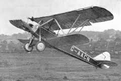
To hypothetically take the 'Airflow' process one step further, if one was to add slats to a Seeker (or Champ, or whatever) I'd assume that to prevent them interfering with the nicely 'developed' centre section stall and vortex characteristics the slats should only be between a little outboard of the fence and the wingtip? Theoretically that should make it even more spin resistant (if that's possible) and give it the ability to reach a higher alpha/lower speed before stalling by overriding the centre section's control of elevator effectiveness when required for STOL operations, by using high engine power to energise the HS/elevator similar to the SuperSTOL in the video below? (See series of high powered landings from 1:30) If one went down that road it would probably remain very reluctant to spin but if it did do so what effect do you think the slats would be likely to have on the recovery, based on the Easy In, Easy Out, Hard In, Hard Out notion of spin characteristics? Hypothesizing - The elevator-inhibiting effect of the reduced downwash from the stalled centre-section is limited; it cannot be worth more than about half the angle of attack at which the centre-section stalls - maybe around eight degrees, at a guess. That was barely sufficient, in the Seeker, to maintain the elevator inhibition over the aircraft's CG range of 11% MAC; without the 3rd stage supplied by the leading edge notch at the inboard end of the ailerons, it was possible to occasionally get the second-stage stall at the aft CG limit, which gave a small wing-drop, but the VGs were keeping the ailerons effective, so one could easily catch it with aileron. When the leading-edge cuffs were added, with the VGs on top of them, it became impossible to get any wing-drop at all. So, firstly, the secret to spin-resistance is to use a small number of discrete devices that generate powerful chordwise vortices that rotate the opposite way to the tip vortices, as soon as the stall propagates to them from inboard. The fences and stall strips do that for the first-stage, and the sharp inboard end of the leading-edge cuff does it for the second stage. And at each step, you want a graduated increase in the stall angle. My guess would be that you could make this principle work to higher lift coefficients by a suitable application of slats. Quite how you would work the second major chordwise vortex at the inboard end of the ailerons, eludes me. Anything approaching full-span slats raises an enormous problem with the undercarriage, though; Handley-Page demonstrated that with his Gugnunc (see photo) and the Alaskan super-stol gadgets also give ample evidence of that. Also, slats - even retractable ones - always cause substantial increased drag. I flew the sole example of a Rallye Commodore in Australia a bit, and I'll never forget landing it on the 06 runway at Camden, at light weight one afternoon, into about a ten knot breeze - it stopped literally within the length of the piano keys; the student waiting to line-up in a 150 gave me a staggered look as I turned off under his wingtip. One of those moments, it was . . . However, I came to agree with Randy Green, who had done the first-of-type testing of the first Rallye into Australia, that it was essentially a landing-and-taking off device, rather than a thing for going places. I never tried spinning it; but I suspect the designer's strategy was to make the wing stall angle so great that you could never reach it. VGs are less spectacular, but they have very little if any adverse effect on the cruise or climb performance, so are more useful in my view, unless "super-STOL" is your prime aim.
-
Do vortex generators really work.
Dafydd Llewellyn replied to stevron's topic in AUS/NZ General Discussion
Thanks, Tom. I'd use VGs on my own aircraft - but set up for the improved stall behaviour, not because of the numbers. What they do, is to make the full speed range usable. One of the demonstrations I have used in the Seeker, is to simulate a violent evasive manoeuvre - such as one might make if somebody were shooting at you - from 65 knots (the flaps-up stall speed being 56 knots): Boot full rudder, full aileron, stick on back stop and full power, to haul the thing into a tight turn. Any normal aeroplane would flick-roll from such treatment. The Seeker simply turns and keeps flying, with a barely-perceptible buffet from the stalled centre-section. The people marketing VGs are pushing the wrong aspect of them, in my view; used properly, they are a magnificent safety device. Used wrongly, they are bloody dangerous. I just wanted to explain that to people. -
Do vortex generators really work.
Dafydd Llewellyn replied to stevron's topic in AUS/NZ General Discussion
I'd take those performance figures with more than a grain of salt; a lot of the marketing of VG kits relies on the increase in angle of attack causing an increased pitot-head error. He's not saying whether the speeds are IAS or CAS - so you can bet they are IAS. To get REAL speed values, the testing would need to be done using a certification - type airspeed calibration rig. The VG kit on the Seeker was originally supplied by Micro-Aerodynamics http://www.microaero.com/ - but of course they did not have an STC for the installation, so Seabird got a shoe-box full of VGs and some general advice over location, spacing etc. So Seeker had to do their own experimentation, as I have described. It WAS done using a certification airspeed calibration rig, so the speeds were real. What it showed, was that at the full aft CG, where the aeroplane was not elevator-limited, the full-span VGs gave an increase in the maximum lift coefficient of 16% - but with totally unacceptable stall characteristics. By the time the stall behaviour had been tamed, the increase in maximum lift coefficient was 13%; and since the speed change is proportional to the square root of the lift coefficient, that gave a reduction in the real stall speed of just under six percent. If the full-span installation had given acceptable stall behaviour, the stall speed reduction would have been just over 7 percent. That's quite a bit less than Stolspeed are claiming, which suggests to me that about a third of their claim is in fact due to the increase in pitot-static system error at the higher angle of attack. Their claims re cruise speed and rate of climb also do not fit with my experience; there are well-defined methods to measure those things, and they are not as simple as you might imagine. Climb performance as required for certification is usually the result of a set of twelve climbs, half of them on reciprocal headings to eliminate any wind-shear effect, corrected for aircraft weight and density altitude, and averaged. The test conditions must not have any temperature inversion.