Bigglesworth Posted August 16, 2007 Author Share Posted August 16, 2007 Fool tank and other fibreglass disasters {The updated fuel tanks are a lot better, don't let this put you off} The fuel tank is comes in 2 pieces which are meant to fit together but don't really. The instructions say 2 layers of cloth to join it. So cut tank to make it fit, sand up area to be bonded, then fit fibreglass. Nice and easy. There one fuel tank. Only problem is that it leaks like a sieve. Check instructions. 'When fuel tank leaks, put a patch of fibreglass on it" so I did. In the general area of the flow anyway. Got annoyed when it leaked for the 5th time. Painted the whole of the join with resin. Thats better, only a few leaks. And no more resin. Now if you've ever tried to get vinyl ester resin in small quantities, you will know the difficulties. Nearest shop is 3 hours away in Canberra, and then they had to get it from Sydney.......... Anyway, I finally got some, and started patching again, this time thick resin. It did eventually look like a bond, and at last count there was only one small pinprick. It was then that Garry mentions that the best way to do it is to put down 2 layers of cloth, then give it 2 coats of resin; isn't it obvious? Now that makes sense. Anyway the end is in sight. That probably doesn't interest you since it was all my fault and there is a new tank design now anyway, but it frustrated me so much that I had to tell someone:;)4: The other thing which needed the vinyl ester was the undercarriage leg. It has to be first cleaned up, then covered with cloth, some uni glass around the stress areas, then filled and sanded. I just gave it a rough down with the rasp, got all the bubbles out, then put the cloth and uni on. Mistake. First, it should have been sanded to a streamline shape. And when it has the sharp corners, the cloth won't follow it and bubbles big time. So it was either try to fill it or start again, and as you know I am fussy with some things. So one fine day I hit it with the flap wheel in the angle grinder. Took off all that I had done before, and a whole lot more. Smoothed out all edges, and tried not to weaken it too much. Then I filled it BEFORE I wrapped it. This meant a lot less bubbles in the cloth, and a lot more strength. I put more uni around it and wrapped it TIGHT this time, it couldn't come away. Now it looks better. Of course, just that day I wrapped it, I spoke to Garry and he said that it need more uni. Oh well. It can go on top of the cloth. Then I still have to fill and sand it. And fit axles and wheels to it. Link to comment Share on other sites More sharing options...
Ultralights Posted August 16, 2007 Share Posted August 16, 2007 a good way to increase the strength of the fiberglass in the undercarriage is place it under a vacuum! not only will it eliminate all air bubbles, but force it around bends, and more than doubles the final strength. a normal household vacuum can be used, all you need are a few sheets of plastic, bleeder cloth, these can be rags, and sealing tape. a finishing ply placed directly over the wet glass will give a nice finish, we usually use silk cloth. but perforated plastic can be used as well. Link to comment Share on other sites More sharing options...
Bigglesworth Posted August 16, 2007 Author Share Posted August 16, 2007 D box or Da B**ch So the wing looks like a wing, all it needs to make it stable is a piece of sheet aluminium wrapped around the front. I like the sound of that, nice and easy. So first, cut out the shape of the sheet. Thats not too hard. Well, not if you are not crammed for space, and carrying a sheet by yourself and get a horrible little dent in it. Ok so that will have to be flattened out, or at least flattened in and the rest filled. The sheet is covered with fabric anyway. So the shape is cut out, now it needs to be pre-bent. I made up 2 bits of scrap with the profile of the ideal bend for the root and tip rib, so now I know what the sheet should look like. To bend the sheet, 2 people are needed. Well unless you are the only one there and are too impatient to wait for help. I pre bent it myself. Got it almost right (I thought anyway). So then I fitted it to the wing. I had bought a handful of cheap ratchet straps to pull it back with and thank God I did. I still had to use a couple of ropes and I never got these anywhere near as tight as the straps. Even when I raided my bosses supply of tie downs, I still had to use one rope. Anyway, no matter how tight I got the straps, the bottom still wouldn't come up to the rib. Rang Garry, "how close does the sheet have to be to the rib" he said pretty close but I might have to pack it out with wood. Started doing this, but needed too much wood, figured it needed more bending, I did that myself as well, and being annoyed at having to pull it off I gave it a good bend. Mistake.:black_eye: [ATTACH]3299.vB[/ATTACH] I put this on and the leading edge wouldn't pull in. [ATTACH]3300.vB[/ATTACH] So I had to unbend it. This needed two people. And was still very difficult. And took about 4 tries.'wb' [ATTACH]3301.vB[/ATTACH] I still unbent it a bit more after this pic was taken. But then I made up a feeler gauge buy fileing a rivet tail down, and when I couldn't fit about 0.75mm through the gap at the front, I figured it was good enough. I generally work to 1mm accuracy. ( about 10 times GA standard):;)2: [ATTACH]3302.vB[/ATTACH] So now, a day too late, it fitted not too bad. I still had too fit a few well placed pieces of wood. [ATTACH]3303.vB[/ATTACH] Then I had to set the wing up in a spot where I could get to the spar top and bottom to drill it. It balances with the spar just over the edge of the bench so I set it up there. Of course I didn't fit a waterline there so I drilled a hole in the middle of the bench to put the waterline through. Sounds a bit extreme but iots my bench, I can do what I want with it:confused:. [ATTACH]3304.vB[/ATTACH] [ATTACH]3306.vB[/ATTACH] I then blocked up the drag spar at the root and tip until I got the root level, and the trailing edge of the tip 18mm up. [ATTACH]3307.vB[/ATTACH] [ATTACH]3305.vB[/ATTACH] The exact wash out isn't important, it is only important that both wings are the same, otherwise it is only good for circuits. In one direction;). So before I fitted the ribs to the spar, I held the two tip leading edge ribs together and marked the same reference point at the front on them, and did the same with the root. Now I just have to get the other one with the same mistakes and it will fly straight. Talking of mistakes. I got ANOTHER dent in the sheet. Don't ask me how, I just noticed it later on and was extremely annoyed. I still haven't drilled the sheet yet, it was late when I finished setting it up and I didn't want to do anything that critical that late. So I am trying to thing of problems now, before I make them on Friday. Help me brainstorm, I have got the sheet tight to the ribs, have got the trailing edge lined up, have the washout 18mm up at the tip trailing edge....... What more do I need? Actually I need more Clecos; I only have 20 1/8th clecos and something tells me I wish I had more. But 10 either side should hold it. especially if I don't move it. I also will need more countersunk rivets. The kit supplies uni rivets for a lot of work, but I preferred the countersunks and used them up there, now I will need more. Also, after I drill it, I have to take it off and clean it up (do the counter sinking/dimpling etc) and while I do that, I want to coat the inside and the spar with primer for protection. Despite all assurances, I want to be sure of the D box since I won't notice it if it corrodes. I will just use a bit of etch primer, since it really doesn't need anything so that should do. The inside of the D box is pretty special in as much as once it is fixed on, there is no getting inside it. (Adam Sandler impersonation "And not many people know this, but you can hide your weed in there:laugh:") Link to comment Share on other sites More sharing options...
Bigglesworth Posted August 16, 2007 Author Share Posted August 16, 2007 a good way to increase the strength of the fiberglass in the undercarriage is place it under a vacuum! not only will it eliminate all air bubbles, but force it around bends, and more than doubles the final strength.a normal household vacuum can be used, all you need are a few sheets of plastic, bleeder cloth, these can be rags, and sealing tape. a finishing ply placed directly over the wet glass will give a nice finish, we usually use silk cloth. but perforated plastic can be used as well. I got it tight with next to no bubbles in the end, would a vacuum have made it still stronger? I can't see it doing so since I left no space where a vacuum could hold it further in. It probably would still have made it easier though. So do you leave the vacuum running until the glass starts to set or just to get it in position? Link to comment Share on other sites More sharing options...
myshed2 Posted August 19, 2007 Share Posted August 19, 2007 Hey BW I might be talking cr.....p here but you wanted brainstorming. It sounds like you pulled the D box sheet onto the ribs and got it sitting right and then set up the washout. Do you not think that you should set up the washout first, in case the D box holds the wing in its original position (without washout)??? Link to comment Share on other sites More sharing options...
Bigglesworth Posted August 19, 2007 Author Share Posted August 19, 2007 Hey BW I might be talking cr.....p here but you wanted brainstorming.It sounds like you pulled the D box sheet onto the ribs and got it sitting right and then set up the washout. Do you not think that you should set up the washout first, in case the D box holds the wing in its original position (without washout)??? All suggestions will be considered. Thanks for posting. When the D box is tied on, the only thing stopping the spar from twisting is the friction between the d box sheet and the ribs. This is not much and easily allows the wash out to be adjusted later. I had to move the trailing edge about 25mm from where it naturally sat to where it had to be. This needed negligible force to move. Now that I have put the d box on, it is hard to move it 5mm either way from where it was set up to. I will tell you all the full story tomorrow, I'm too tired now. Local dairy farmer needed a hand with the morning milking on saturday so I was working from 6:15am and only stopped working on my plane at 2:00 this morning. Slept in big time this morning, but I still need more sleep. If there are any interrogation officers out there who want to legally use sleep dep. just give you prisoners a kit aircraft. Link to comment Share on other sites More sharing options...
Bigglesworth Posted August 20, 2007 Author Share Posted August 20, 2007 More about da box So last Tuesday I left the wing sitting there all ready to be drilled. When I got back last weekend, I first checked that the washout hadn't moved. Of course during those days, the water in the level had changed so I had to readjust that. It was in doing this that I realised that I had made a grave error the other day; the water level at the tip is used to measure the washout, I had set it up with the water mark level at the front of the bench, and measure at the back. measuring about 600 away at funny angles is very susceptible to parralax error, I was out by about 4mm. Shifted the water line so it is level at the back (easy to line up) and measured at the front (hard enough when you can get to it). So all was set, BUT: the only thing holding the wing in position was its own weight on pieces of packing, so drilling from the underneath was likely to disturb it. So I started on the underneath knowing that I could still adjust it before I did the top. Ever tried to drill over a hundred holes upwards? from sitting position? My arm was very painful at the end. But I got it done, and clecoed. Well, just clecoed, I only have 20 clecos of that size, hardly enough for a 3 metre wing. [ATTACH]3337.vB[/ATTACH] Anyway, so I set the wing up again, it hadn't moved much (maybe 1-2mm), then started drilling again. Once I had the top side of the spar drilled, I could loosen off the ropes one by one to get to the ribs and drill them. Now that is easier than it sounds. Being fibreglass, the ribs are slightly flexible and could be anywhere within 50mm of their correct position. Actually they all were OK and I was worried for nothing. What I should have worried about was that I would not notice the rib because it was so thin, think I missed it and drill another hole beside it before I realised that I was right the first time. [ATTACH]3338.vB[/ATTACH] Bugger.:black_eye: It is all covered with fabric so it don't matter.:;)2: Well it doesn't matter compared to the next problem I found, I should have rechecked the ropes before I started drilling; they must have stretched slightly since I had set them up, now the sheet was about 5mm away from the rib underneath.:;)1:. I didn't like it but too late now, just held it down and drilled it, tried to cleco it, but they don't exactly hold in fibreglass, so I just had to assume the set amount of rivets would do. Once I had drilled all I could get to, I shifted the wing and drilled all the rest. There was only the trailing edge ribs which I couldn't get to, and I figured they couldn't move much if there was no load on them. So...... All holes drilled. And there was a heap of them too. That sounds like logic: what sheet has the highest stress on it? So what sheet has hundreds of holes drilled into it? . Maybe they work on the principle of the Salada crispbread: it will never break on the perforations..;). I took the sheet off (gently, if I ruined this sheet, it was a new wing; no hope of picking up the holes again) then started cleaning the holes up. Inside of the sheet was just taking off all the dags, then from the outside I had to dimple some holes and countersink the rest. The dimpled holes are where the sheet attaches to the trailing edge ribs, this is covered so it doesn't matter it it sits a little proud. Where it attaches to the spar between the root and next rib, it is meant to be unis there. But I am fussy, I put dimpled countersunks, then had to countersink the spar. All the extra work for a little less resistance. Then I wanted to have some metal protection on the inside of the D box where I couldn't see it to monitor corrosion, so I painted the whole lot with etch primer. This is meant to be sprayed on, but it wasn't worth getting the spay gear out for, so I brushed it on since no-one will see it. probably only got 50%coverage on the first coat. [ATTACH]3339.vB[/ATTACH] But by the 2nd it was OK. I then roped it back up. Set the washout up again and started rivetting. I started from the leading edge where I figured that if I had to drill them out I wouldn't hurt the fibreglass, and it was still laterally moveable once the were attached. I soon realised what I had expected: there weren't enough rivets in the ribs to hold it flat. Either that or I hadn't done a good enough job:sad:. Too late then, I finished rivetting off the rest, then turned the wing over to get a better look at it. Agreed with myself that it needs more rivets, so I drilled some more holes and fitted about another 2 to each leading edge. When I drilled these, I had the air duster on them to blow away all swarf so that none got into the wing. The sheet still ripples slighty in places, but not too bad. [ATTACH]3341.vB[/ATTACH] Talking to Garry later, he said his also has some ripples, he said that he has seen it done perfectly, but it required the use of at least 150 clecoes. A bit different to my 20.:). Anyway so it is on, I am happy that I got the washout right, and its sits reasonable. What more could a plane builder want? [ATTACH]3342.vB[/ATTACH] [ATTACH]3340.vB[/ATTACH] Now I have to do the other one, more of the same headaches. I don't know whether to get it perfect or keep the plane symmetrical, I think I will try to get it perfect and end up symmetrical anyway.:confused: Thats the problem with the wings: there are 2 of them. It gets boring by the 2nd one. Something tells me I have a short attention span. Link to comment Share on other sites More sharing options...
Bigglesworth Posted August 20, 2007 Author Share Posted August 20, 2007 Nice legs............ Something else I did over the weekend was set up the axles. Pretty simple. I mounted the undercarriage, then fixed the axles loosely to it. I already had drilled the holes for mounting the axles, but I had drilled them straight when they needed to be sharply angled down, wriggled the drill until it was right. The angle for the axles is 1/8th forward at the tip, and 1 inch down. I set up a bar underneath it to sight forwards to, and I clamped a bar to the side to sight the up and down. [ATTACH]3344.vB[/ATTACH] [ATTACH]3345.vB[/ATTACH] All was set to fill in behind it with bog, but my mind was too cold/late at night. I mixed up the wrong bog (polyester instead of vinyl).'wb' Luckily I realised before I put it on the leg, but I still didn't want to waste the bog, so I used it to finish up the wingtip I started on the other day. (did I tell you about that, can't remember). picture from earlier [ATTACH]3346.vB[/ATTACH] Then I mixed up the right bog, and spread it behind the axle mount. Moved the axle so it was touching at the bottom but angled too far down, then I slowly tightened the top bolts up until it was right, and did the same on the other side. Now that I see it, I probably took more out of the leg than I had to to fit the brake line: the bog keeps it out about 10mm. So now it has some legs, but there isn't enough space in the workshop to leave them on, I keep tripping over them. Actually with the green legs (I haven't filled them with Q cell yet) it looks a bit like a frog. Just don't tell Garry I said that. ;) [ATTACH]3343.vB[/ATTACH] I also got the rudder cables worked out, forgot to take pictures though. It wasn't very hard, I just worked out where they were meant to go, cut a hole in the cargo bay back for them, cut pieces of tube for them to run in beside the frame, a bit of extra tube where the load is, front and back, then positioned it all up. Crimped the back first, then worked out where it felt right and crimped the front. Crimped, that is, with the pliers. I will undo all the cable ties and take it to someone who can do the job properly for me. Then it will be able to wag its tail to show how happy it is to be built.:;)4:. Link to comment Share on other sites More sharing options...
myshed2 Posted August 20, 2007 Share Posted August 20, 2007 As if milking cows at some ungodly hour of the morning and then working on the plane till 2am isnt enough, you still have time to religiously post your latest exploits. I for one certainly apprecaite it BW. Link to comment Share on other sites More sharing options...
Bigglesworth Posted August 22, 2007 Author Share Posted August 22, 2007 Too cold I tried doing some more work on Tuesday, but it was too cold. I have found a poem which describes my feelings entirely, just see if I can post it. " WINTER " a poem by Abigail Elizabeth McIntyre Sh*t! It's Cold ! There was a winter pic with it, but not worth including. Hope no-one else suffers from it like I did. PS, I got a bit done, but not enough to write....um....(not home) about. Link to comment Share on other sites More sharing options...
Bigglesworth Posted August 22, 2007 Author Share Posted August 22, 2007 As if milking cows at some ungodly hour of the morning and then working on the plane till 2am isnt enough, you still have time to religiously post your latest exploits. I for one certainly apprecaite it BW. Glad people like to hear me speak, they normally tell me to shut up;). Over 1100 hits, thats the most attention I've got since.....um.....well...... better not talk about that. Seriously though, my posting here might take a fair bit of typing time, but it means I have a whole bunch of experienced people out there to help spot mistakes before they become fatal. This is important to me since I will not be able to get a professional to check it out before I cover it (the nearest is too far away) and I am by no means a professional myself. So it is mutually beneficial to me and the readers, and that is the way the world should be,;). Link to comment Share on other sites More sharing options...
Bigglesworth Posted August 27, 2007 Author Share Posted August 27, 2007 All over again As I said, by the time the 2nd wing is done, it is getting monotonous. On the other hand, new mistakes are always cropping up so there is always a new reason to make a plane builder realise that he is still nowhere near perfect. I have got the 2nd wing D box drilled, cleaned up and countersunk/ dimpled. And that horrible deep scratch taken out of the sheet. Yes, one of those things which make you mad. I was innocently drilling holes in the wing thinking how easy this plane building lurk was, when IT happened. I was drilling near a strap. These straps are plenty long and have a lot of overhang. The overhang was right next to where I was drilling. And you can tell where this is leading.......... I caught the strap with the drill when I was about halfway down the hole.The drill bit bent but it was still able to deeply score the sheet about 30mm from the hole towards the the rear. I spent over an hour with the file, then 60 grit then 150 grit then 400 to get it smoothed out. Now it is weak around one hole, but at least it won't crack. Also it is in a place where I can keep an eye on it and if it starts to play up, I will put some paint over it so I won't see it ;):confused:. I didn't meant to say that, but someone stole my delete key:;)1:. So I got the 2nd D box done, no pictures, you wouldn't be able to tell them from the last lot. A few interesting new points. This time I focused on getting the sheet sitting hard against the ribs before I drilled it, also I put about 5 rivets per rib on the underside of the leading edge. I will be interested to see if this makes the sheet sit perfect without any ripples. Will let you know if it does. (if it doesn't, I'm not telling anyone I went to all that work and still failed to get it right:)) I ran out of rivets the other day as well. This is not really Garry's fault, I used countersunks in a lot of places where he allowed for Unis. And I probably closed the spacings by about 2-3 times what he has; he is pretty mean with rivets while I am the opposite. So I need about another 400 or so which should turn up on Friday. Hardware takes too long :;)1:. This time I got the bend right on the sheet. I waited until my boss had time to help me, and we did it slowly, probably fitted it about 5 times at least before I was happy that it sat right. I took a photo of the last time to show how much it needed.The real killer is the differential in the root and tip. By the way, My boss got his GFPT on Saturday 'be'. Everyone say Good onya Lex. He reads this forum although I think he is yet to make a post. Link to comment Share on other sites More sharing options...
Bigglesworth Posted August 27, 2007 Author Share Posted August 27, 2007 Them things what go round and round and flat. Wheels are neccessary on an object designed to sit on air.;) However, they are not very important to me since I hope they will not be used too much, I want to stay up there if I could:big_grin:. I have told you about when I fitted the axle stubs to the leg, what I didn't tell you is that I forgot to coat the stubs with vaseline or similar and now I have Buckleys and none of getting them off. Not that this is neccessarily a bad thing, but I wanted to be able to. So I have them tight on. I then slid the brake system over it. I got the disc brake option for a few extra dollars, but I am the first one to do so, so there were teething problems which didn't matter too much. Garry has been very good about it; when the spacer tube which holds the wheel on was too short, he made me another one the right length, so that sorted out easily. The whole brake assembly is held on by a tube over the axle which has a bolt through it. To get the last bit of movement out of the assembly, I slid the caliper back over and held it tight while I did up the grub screw. Not that it wants to be tight, but it needs to be firm. The spat was next, this has one bolt at the front which screws into the end of the spacer, and two at the back which hold it to a bracket which needs to be bent to shape. The centre holes are marked out on the spats so they work for reference points, I simply measured the shape of the cutout, marked it and cut it. It fits snug, and it easily removeable to change a tyre. (quite likely occurrence seeing they are 2 ply tyres. Um... bindis?) The bracket at the back is made from a bit of steel flat, a bit of a nuisance to bend, but I soon got used to the large radius curves it makes. I will still do more on the spats later to lower wind resistance. While I was working on the brakes (they are BX1000 brakes by the way, independant toe hydraulic, good/better than GA), I looked at fitting the brake line to the master cylinders. Uh Oh. Problems. The fitting is on the bottom, roughly where the floor is. So either drill a hole in the floor (possible, that would hide the lines) or find another way. I slid the cylinders as far up as they would go, still not enough, it would crimp the brake line quickly, so I think I will have to buy some 90 degree angles, and maybe still need to carve a bit out of the floor. If this works I will tell Garry and the chances are the next kits will have all the neccessary parts. Link to comment Share on other sites More sharing options...
Bigglesworth Posted August 27, 2007 Author Share Posted August 27, 2007 flapping things I finally can make it flap its stabilators. This is a really big step forwards since it meant that I can sit in my plane, make engine noises, play with the controls, AND THEY ACTUALLY DO SOMETHING, it is just like its finished then:). Playing aside, time to do some real work. The stabilators are built around a piece of 40mm tube which slots over the steel tube which is held to the plane. The stabilators are held on by a bolt stuck through them and the steel tube. It is not tightened up, so it can be long enough so it can stick through the skin and be removeable, that makes the stabilators removeable for small doorways. Interesting note, the distance between the outer extremities of the stabilators when fitted is just under 2.7 metres. I think Garry, as an ex-chippy would have know that a standard roller door is 2.7 metres, and thoughtfully made it so it fits. He likes to make it easy for people. This bolt which holds the stabilators on has to be tight. That way it will stay in, and totally stop movement. First the plating has to be sanded off the stem since this will wear off otherwise leaving a gap, then the hole has to be reamed to exactly the right size so the bolt has to be tapped in with a hammer. Now to find a 5/16th reamer to borrow off someone is rather difficult; no-one has one that small. So I had to buy my own for just this job. Cost me $35 off ebay. If anyone want to borrow it for building a Cheetah, let me know, I don't need it anymore. So first I positioned the stabilators. I put the joystick in the neutral spot, not too fussy, there is plenty adjustment in the cable, then set the stabilators (any shortening for stabilators? takes too long to type:sad:) in the neutral position. They sat a bit loose on the tube, so I wanted to put some aluminium tape around it to hole it tight, but I didn't have any, so insulation tape will do for now;), better change it before I fly it. But on the other hand, it will probably work just as good. The normal way to set up the stabilators is to set a straight edge across the trailing edge and drill it there. But I found I could sight it better. [ATTACH]3390.vB[/ATTACH] Thats Lex in the background Then I found that that was wrong too. I had made a slight (3-4mm) twist in one side, and a straightedge would carry that twist into the setup. That is, if one side is out by 4mm in one metre, over 2.64m, it would be out about 10mm which is a lot too much. So the way I worked out to level them was to look from the back and line the trailing edges up with the main tube, and adjust them so they both lined up the same. That way errors can be averaged out and not talked about:confused:. [ATTACH]3392.vB[/ATTACH] It isn't too bad. So then the neccessary prayer before any major work, and drilled it. This was the first hole in the plane which needed a pilot hole, but I had a 9/32 drill as a final and any wobbling would go too far. Then came the real annoying part: I knew that the 9/32 hole needed very little reaming since I had tried it out on some scrap, but I didn't know that with a lot of tapping, the bolt fitted into this drill hole. I didn't need the reamer after all:clap:. Actually, it might be a bit too tight; it went in alright in the afternoon sun, but when I took them out it was in the evening and a bit cooler, it needed a fair wollop to take them out, that would look good; wacking your plane with a lump hammer:laugh:. The other side went in much the same, only, of course it can't all go well, both bolts are at noticeable angles to the side, my drilling was a bit out. Oh well. Change subject,,,,,,, don't you think it looks like Frankenstein??? [ATTACH]3391.vB[/ATTACH] While I had the plane out of the shed, I couldn't resist putting the wing on it to see if (cross that out) HOW it fits. Actually it is good. See I marked it with the trailing edge too high because thats how it wanted to sit, then I allowed for a packer under the drag spar mount which evened things out; it sits about perfect. Talking of putting the wings on; I asked Garry how important it is to get the wings square, he said I could measure from the centre of the firewall, and if they're withing 3 foot of each other at the tip, she'll fly beautifully. Now that's the sort of building I can do ;);). I had to cut the seat around the drag spar but that was easy enough, then I got to sit in it and play wonderboy aviator (all Spike Milligan fans will know that that is a twisted quote from the Goon Show, very funny show that was). So I got to sit in it, with some temporary upholstery and check out how she feels and: :;)7::;)7::;)7: she does it for me already, and she's not even built yet, let alone flying. [ATTACH]3393.vB[/ATTACH] Link to comment Share on other sites More sharing options...
Bigglesworth Posted August 27, 2007 Author Share Posted August 27, 2007 Something else I might warn future builders of: don't set up the root rib too close to the fuse. The sheet can hang over bit and that way the rivets in the rib aren't too close to the edge. Like mine are.:black_eye:. Borderline I should say, they will do and I don't anticipate cracking, but an extra 10-20mm would have been good. Link to comment Share on other sites More sharing options...
Bigglesworth Posted August 30, 2007 Author Share Posted August 30, 2007 The front of the back Now that I have set up the stabilators, I can now build them fully, then balance them, then the rear of the plane is finished to covering, Yee-ha!! The leading edge of the elevators is a sheet of fibreglass. Simple to fit, just put clecoes wherever neccessary to hold it on reasonable, put a board over it with a weight to hold it together, and fibreglass it together. Easy as 3.14 (pi) When I had put the stabilators on, I noticed that there was almost contact between the side of the stabilator and the fuse. So I had to take a bit off the stabilator. This meant that I first had to put a few layers of chop strand in the corner that I had to trim. It ended up alright. [ATTACH]3421.vB[/ATTACH] The outside end of the stabilators are tapered down. This plays merry hell with the leading edge sheet. It can be held down with a multitude of clecos, but it still witt have ripples. Apparently the fabric pulls these in so they are not to be worried about. I set it all up, then roughed up all the areas to be bonded, mixed up some Q-cell and stuck it together. I love Q-cell, it always reminds me of Sci-fi books; they always have a Q switch or Q factor or something Q in them;) So that was left to set. I was worried about the clecoes being stuck in, but they came out fine. [ATTACH]3420.vB[/ATTACH] I rough trimmed it with the hacksaw because there was lots of overhang, then rough sanded the rest with the flap wheel. it then needed a filling of gaps with more Q-cell. I will sand it smooth tomorrow. I even got the 2nd one done today, it went just as easy as the first. Filling, sanding and then fabric time. That will be fun:). Link to comment Share on other sites More sharing options...
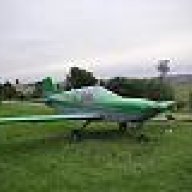
slartibartfast Posted September 4, 2007 Share Posted September 4, 2007 And now for something completely different... a Cheetah. I've been too busy to post lately so here's the last few weeks photos all chucked in largely without comment. Still enjoying the process heaps. [ATTACH]3489.vB[/ATTACH] [ATTACH]3490.vB[/ATTACH] Me having a broom broom moment [ATTACH]3491.vB[/ATTACH] [ATTACH]3492.vB[/ATTACH] [ATTACH]3493.vB[/ATTACH] [ATTACH]3494.vB[/ATTACH] [ATTACH]3495.vB[/ATTACH] [ATTACH]3496.vB[/ATTACH] [ATTACH]3497.vB[/ATTACH] [ATTACH]3498.vB[/ATTACH] [ATTACH]3499.vB[/ATTACH] [ATTACH]3500.vB[/ATTACH] [ATTACH]3501.vB[/ATTACH] [ATTACH]3502.vB[/ATTACH] [ATTACH]3503.vB[/ATTACH] [ATTACH]3504.vB[/ATTACH] [ATTACH]3505.vB[/ATTACH] [ATTACH]3506.vB[/ATTACH] It will probably fly better without Tim there, but it looks right. [ATTACH]3507.vB[/ATTACH] These are in mixed date order. Looking to paint in about 3-4 weeks. Putting lots of miles on the Territory and sleeping in the back about 2 nights per week (no biggie - comfy mattress, doona, pillow, internet access, music). Looking like complying with the 51% rule though - and having a ball. To explain - early on I thought that Tim was going to build it for me, but then I discovered that Garry doesn't have a manufacturers cert yet (compliance cost again - can this be simplified?), so that wasn't an option. Suits me. Factory assist rocks. Everything you need in tooling, materials and advice is right at hand. I highly recommend this path. The added bonus of being completely involved and in control of the process is priceless. Thanks for the shared thread BW. Your boss picked up the sheet and prop today. Spring O'clock and all is well. Link to comment Share on other sites More sharing options...
myshed2 Posted September 5, 2007 Share Posted September 5, 2007 Thanks SBF. Between yours and BW's posts and photos the knowledge base is going up expotentialy. Link to comment Share on other sites More sharing options...
Bigglesworth Posted September 5, 2007 Author Share Posted September 5, 2007 That looks like one sweet plane on the up and coming. Mine feels old already (jk). Also with Tim's professional help, you have got excellent build quality there. If I was an investor, I know which company I would pick to back. I think it won't be long before Morgan Aeroworks will be large player in the field of recreational aircraft. I got my propellor today thank you very much, it will be turning a bit later than yours I think. Not that I work slower, but I have to wait for all my individual extras whereas you can get them off the shelf. Lucky ba....... Link to comment Share on other sites More sharing options...
Bigglesworth Posted September 5, 2007 Author Share Posted September 5, 2007 Who wants to take bets on how long it will be before Ian creates a Morgan Aeroworks section? Link to comment Share on other sites More sharing options...
Admin Posted September 5, 2007 Share Posted September 5, 2007 Who wants to take bets on how long it will be before Ian creates a Morgan Aeroworks section? Not long Link to comment Share on other sites More sharing options...
slartibartfast Posted September 5, 2007 Share Posted September 5, 2007 Woohoo. A Morgan Aeroworks forum. Thanks Ian. I've emailed Garry Link to comment Share on other sites More sharing options...
Bigglesworth Posted September 5, 2007 Author Share Posted September 5, 2007 Wagging tails and other funny bits. The rudder now works, this means that I can sit in it and make it wag its tail and make engine noises and imagine that I can fly. . Of course while doing this I am not getting any work done.. So you could say progress leads to a loss of productivity. Something that didn't lead to this scenario was the sanding, filling, sanding etc of the stabilators. This was a mongrol of a job. It took me hours and hours and I never seemed to be getting anywhere. But now they are ready for covering which makes me happy. And covered in fibreglass dust. :;)4: Back to the rudder. It was reasonably simple to route it, then I just cable tied it off temporarily, slightly crimped the rear Nicos and adjusted the front ones to where I wanted them. I made them as far forward as possible so that large people would fit, and small people can put clamp types on the cable. I crimped these slightly to hold them, then took it all off and got it fully crimped. I put heatshrink tube over the cable ends to neaten them up. [ATTACH]3520.vB[/ATTACH] This seemed to work, but the heatshrink was a bit loose, and when it slid off., there was no way it would go back on. I will get some self amalgamating tape for it I think. The crimping worked fine and they fitted again:clap:. But I ran into problems when fitting the brakes because I had set the pedals forwards, the brakes wouldn't fit nicely. I will need 90degre angles for them. I think I mentioned this before and said I would try to get them into future kits; Garry says he didn't need them so I guess it is just my fault. So I cable tied it back into position, and I will get some glue onto the hidden areas as well just in case it tries to move. I also got the instrument panel made. There has been an update since I got mine, so Garry kindly sent me the updated base at no extra charge;););). I had to put the front deck temporarily back on to get the height, worked that out then cut the panel leg off at the right place,fibreglassed it and clecoed it to the new base. All looks sweet. A bit more filling but not as much as earlier. Mounting it was simplish. There are 2 brackets which hold the top to the front bulkhead, and the bottom just screws down to the floor. Of course it feels like chasing your tail trying to get it straight, but no-one will notice it anyway. Especially once the fur trim hides all the gaps. Now I just have to get instruments and switches to fill it. Not so cheap:sad:. Just got a quote from Jab for a motor with options, $15300.:black_eye: And that doesn't include a cabin heater. Will be hard at work paying for that. Had to work the milkings last week for 4 days morning and afternoon, thats why no posts for a while. Was way too tired. I am starting to work out a wiring system for it.;) I should not be left alone with a Jaycar catalouge, the plans I have for it are rather tricky, but they include an alarm system, and various warnings, all at very little cost and weight. And an eventual dual battery for the CD player (maybe even DVD player) driving 2 6 by 9 speakers which should pump;). Link to comment Share on other sites More sharing options...
slartibartfast Posted September 5, 2007 Share Posted September 5, 2007 Awesome BW. You could have drawn some more expensive gauges. You're right about doing it in the factory. Everything at your fingertips. Advice, tools, materials, jigs, benches, more advice, a finished one to compare it to (invaluable). The compressor alone has saved me from rivet elbow. You won't be far behind though - if at all. You work bloody hard. Walked into a Mitsubishi dealer yesterday with a feeling I'd find the right colour there so I could give the code to the paint guys. There were only 3 cars in the showroom, but one was perfect. Not many bronze cars around, but there it was. It's called Fusion. As a Buddist friend would say, "it was meant to be". Link to comment Share on other sites More sharing options...
Bigglesworth Posted September 5, 2007 Author Share Posted September 5, 2007 Ail-ing-erons No pics for this forgot my camera. I started on the ailerons the other day, they are the things which make the wings rock. I might get a sticker for it "when the wings are rocking, don't bother knocking" So I started off by putting the wingtip on. This got me the trailing edge worked out. Then I put the trailing edge piece onto ribs 4-7. About now I started thinking I should make sure I could reduplicate this on the other side. Oh dear:;)6:. About 50mm difference in the length of the trailing edge.:black_eye: So now to work out what happened and what to do about it. Eventually I worked out it had something to do with the shape of the ribs and the fact that I had only squared them with a set square. One side was splayed and one inward. But on the bright side, rib number 4, the important one for the the position of the aileron, was the same. So one wingtip will overhang the rib, and nothing else will be any different. Then I measured in to find the position of the aileron mount bracket. It was meant to be 255mm in, but due to various factors, (like the moon being in scorpio with venus rising. I will blame anything) there wasn't quite the space I wanted. And to top it off, the aileron sheet seemed too small as well. Maybe it would fit, I'm not sure.(never am. Unless it is a matter of opinion, then I am always sure.) Anyway, I decided to make it a bit smaller. I can't forsee this having any great effect, maybe slightly less aileron response, but it always had response to spare, and they are still large ailerons. In any case, for 90% of the time, they will be neutral. So I measured to where it would fit nicely, plus about 10mm extra(I hate not having anything to play with and then spending all the time trying to stop things jamming when an extra 10mm would not matter either way.) Then cut the hinge plate to fit, made sure that the aileron would have clearance in the full down position, and clecoed this on. Still can't rivet it since I am still short of countersunk 1/8th rivets. Useless local hardware. And I can't make the ailerons yet, I need some 3/32 clecos which I don't have.'wb' See what I mean about Slarti having it easy? I also spent a lot of time filling and sanding the undercarriage leg. Got it almost done. I got the spats made and fitted. This was a bit of a nuisance. Garry marks the bolt positions on each side as reference points. Very handy, if they would be right.;) In the end I had to slot one hole a bit and put a larger washer on it to hide the slot. His system will make it very easy to take the spats off if needed, even the bolts have the nuts glassed on to stop them turning. This needs to be. I will have to put better tyres on than those 2 ply ones. One of them already went down:sad:. it is just too slow to find the leak, and now it seems to have fixed itself;). Methinks tubes at least. Getting back to the filling of the leg; I ran out of Q cell (not Garry's fault. It is had to anticipate someone spilling it often) and went to get some more. But I couldn't get it in small amounts. So I got some microsphere blend stuff. It works a lot better, heaps easier to work with. And that means less sanding. I also got one side of the cabin lining in. held a sheet against the side, marked it, cut it and it didn't fit. Cut it again and again, now it fits:confused:. I need that soon to mount the motor controls on. When I win lottery. Stop press, some pics. I took them the next day. Link to comment Share on other sites More sharing options...
Recommended Posts
Create an account or sign in to comment
You need to be a member in order to leave a comment
Create an account
Sign up for a new account in our community. It's easy!
Register a new accountSign in
Already have an account? Sign in here.
Sign In Now