pylon500
-
Posts
1,412 -
Joined
-
Last visited
-
Days Won
9
Content Type
Profiles
Forums
Gallery
Downloads
Blogs
Events
Store
Aircraft
Resources
Tutorials
Articles
Classifieds
Movies
Books
Community Map
Quizzes
Videos Directory
Everything posted by pylon500
-

If this doesn't excite you, nothing will!!!
pylon500 replied to motzartmerv's topic in AUS/NZ General Discussion
?Do you mean the smoke flares on their ankles? -
I didn't know we were calling the Robin 2160's, an 'Alpha 160' now? OK, I must admit to learning all my spinning in gliders, so stopping and/or starting engines was not a problem. I guess using an aerobatic entry ensures entry in the chosen direction, unlike an Incipient entry (Glider talk), which in powered planes are just as likely to roll out and spin the other way!! An incipient entry (Glider version), is where you are turning, and allow your speed to wash off until you stall. Typically, a glider will roll into the turn and begin a stable spin within one turn, if held. Powered aircraft, and most ultralights, tend more towards rolling out of a turn (about 70% out, 30% in) and spinning in the opposite direction. As for the recovery technique, yes, it's one way, and as I suspected, in an aircraft with an all flying tail. Aircraft with normal tailplanes will begin to recover as soon as you let go of the stick. The Robin, with it's HUGE rudder, will stop it's yawing motion fairly quickly with rudder, but depending on elevator position (anything aft of, a bit forward of centre) can enter a spin in the other direction. In a glider like a Blanik, once a spin has been stabilised and still holding back stick, use of opposite rudder will do nothing for at least two and a half turns (if at all!) before slowing it's yawing motion, it can then enter a spiral and build up speed VERY quickly. Primarily, as mentioned early in Sally's post, detection and prevention (or at least instant action) is better than allowing a spin to develop. WET ! Arthur
-
Interesting video, some observations; These are what I would term 'aerobatic' spin entries, via the use of full back stick and rudder while still at flying speed. This usually results in a snap roll which will stabilise into a spin after a turn or two (as the commentary says) Real spins occur at very low or stalling speed, often when concentrating on some other problem like an engine failure or trying to stretch a glide when turning low on final. It is more important to be able to recognise the situation or onset of the stall, ie; buffet, heavy elevators yet vague ailerons, or the 'quiet' of the aircraft. As for the recovery shown, I've never seen this method before, it works on this aircraft, (obviously) but I'm not too sure why? There are very few aircraft that will remain in the stalled (and therefore spinning) attitude when you release the stick and pedals, as he demonstrates. His recovery is to put hands on dash and apply opposite rudder, implying that rudder alone is stopping the spin?, or are we to assume that the plane is so pitch sensitive that the act of two people leaning forward is enough to unstall the aircraft while the rudder stops the rotation? Would be interested to know what type of plane it is...? The engine stopping is a bit of a concern, I'm assuming it runs out of fuel within three rotations?! Maybe the use of a fuel pump would be prudent. All in all an interesting video, but I think the more generic version of recovery, "Stick going forward with opposite rudder until rotation stops, then recover", is the preferred method. Arthur. ps, remember kids, don't try this at home, we're not allowed!!
-
I'm not really sure of the back pressure requirements of the 912, but I'm sure it will be AS LOAD AS YOUR POST!!!
-
Maj Millard said; Tomo, if I remember right, I think there was a facet pump in one of the assorted boxes in the trailer....? Arthur.
-
What fabric to use?
pylon500 replied to Pilot Pete's topic in Aircraft Building and Design Discussion
As I mentioned, Dacron (which is a trade name) is a woven Polyethylene fabric, typically used as sailcloth on yachts and early hang gliders. Dacron is woven then heat rolled (which gets rid of some of the shrinking tendency) to partially seal the weave, making it less porous. Mylar is a variation on polyester that tends more to be supplied as a 'film' or sheet, and has a fairly high stiffness for any given thickness. Mylar is typically found as a thin, stiff sheet, used to hold the shape on hang glider leading edges. Utralam is actually a combination of various components. Typically it consists of a layer of some form of cloth which has a layer of some form of film laminated to it, either on one side or both. These 'laminates' are usually found in the sail cloth world (again), and also found on hang gliders. The general form is Dacron cloth with a film of mylar heat bonded to one side, to be used as the upper surface of a hang glider wing, sometimes the cloth can be an open weave of Kevlar or Carbon fibres with a film on both sides as used on larger yacht sails. Anymore questions? Arthur. -
What fabric to use?
pylon500 replied to Pilot Pete's topic in Aircraft Building and Design Discussion
Having done a few cover jobs, I can see some miss-information sneaking in here. To start with, I think Pete.Bess is looking to do a 'glued on, heat shrunk and doped over' fabric job. This is achieved by using any of the 'Polyester' fabrics, whether called 'Ceconite', 'Polyfibre' or 'Stitts' (they're basically all the same). Once you have some fabric, the decision then is how to do the next two processes, finishing the fabric covering and then painting. The early systems combined the last two steps into one simply by finishing off with coloured dopes. The miss-information is occurring when people start mentioning 'Dacron', 'Mylar' and 'Ultralam'. These are basically sailcloths, usually stitched into shape, pulled over a structure and tensioned with straps or lacing, and usually left in their natural dyed finish. Yes, they will heat shrink to a degree, but not as much as purposefully non 'pre-shrunk' fabrics like the Polyesters. The Polyesters are available in a limited range of 'weights', typically 1.8oz(per square yard), 2.7oz and 3.6oz (exact weight numbers may vary). The 3.6oz is a really tough cloth for use on areas of possible high wear or damage, like undercarriage leg frames, or the lower surface of flaps on low wing aircraft. The 2.7oz is the most common weight used on fabric covered aircraft. The 1.8oz is a lightweight fabric, typical on early wooden gliders, many of the early ultralights and over already covered surfaces like turtledecks, plywood sheeted areas and the like. 1.8oz and 2.7oz can sometimes be acquired as 'Non Certified' at a lower price, but is usually still the same product, and suitable for ultralights. There are a few variations on what I've said here, like doping and painting Dacron, using Dacron as a laminate over foam structures (think Ken Rand) and 'pre-sewing' Polyester 'envelopes' to speed up covering (although I feel the time taken making the 'sock' negates any time on the job). There are many other points to consider in covering beyond what I've said here, things like adhering the fabric (look into the Foxbat system, very interesting), mechanical fixing, stitching, taping, overlapping, reinforcing, access panels, chafing etc. It's all fun Arthur. -
How NOT to land a 701/Savannah thingo
pylon500 replied to Ultralights's topic in Aircraft Incidents and Accidents
That's not a hard landing, THIS is a hard landing:bye: -
Just found this on Youtube, so added here;
-
Another impossible dream. Maybe not.
pylon500 replied to Deskpilot's topic in Aircraft Building and Design Discussion
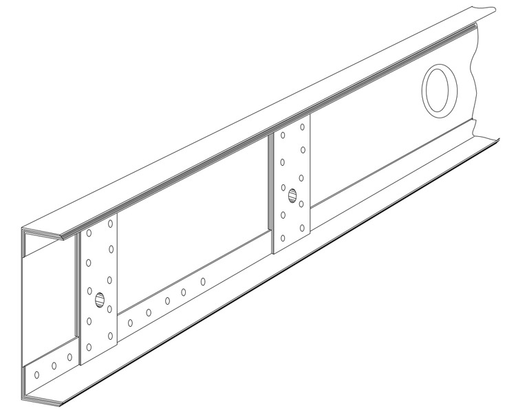
G'Day Doug, Just looked at you latest renderings and where you have understood me, you have depicted well. Now for the bits I obviously didn't describe well enough; In the first picture, the 2' overlap is correct (this gives you a 22' span), the depiction of the laminated angles is incorrect in two ways, the longest angle (light green) should be around two thirds of the length of the C spar (8'), the second angle (dark green) should be around one third the length (4~5'), and the smallest angle (blue/grey) should probably be around one quarter of the spar length (3'). In both the first and second picture you should depict two sets of angle doublers. The ones shown should be sitting in the bottom of the channel, and a second set should be up inside the top of the channel. In hindsight (and looking at your graphics) I can see it would be easier to rivet these angles to the C channel spar through the top and bottom flanges (caps) to avoid confusion when riveting the wrapped leading edge flanges onto the vertical (web) part of the spar,as depicted in picture 4. You also need to do these drawings for the other wing, showing the C spar the other way so they overlap. This may show up some other possible problems....... The folded trailing edge is pretty much as I described, the details would be in the diameter of the rib tubes to dictate the width of the trailing edge. The diameter of the rib tubes then needs to be decided via the compromise of how much unsupported rib can be carried, versus the amount of bracing required, versus the weight penalty taken by using bigger tubes? Smaller diameter tubes will need more bracing (ie 1/4"Ø) whereas larger diameter (3/8"Ø)would need less, but would be more bulky and heavier? If building a constant chord wing, then the ribs are all the same, why not knock them up out of sheet alloy as per normal procedure? Have a look at my 'mass produced' ribs in my Stearman project; https://picasaweb.google.com/113292981019876413104/MurphyRenegadeStearmanProject They are not really that hard to do. Back to the spar web, yes, use lightening holes, flanged as depicted. They could be a little closer together than drawn above (what pitch did you use?) These would run from the tip to about the one third from the centre, try to avoid having a hole line up with the end of a doubler angle. OK, the wing joining bit... Forget about the 1" square tubes, I've had a netter idea.. You have the two spars overlapping back to back for about 2' in the middle, you need to figure out how wide the fuselage is at this point and determine what the wing is going to attach to on the fuse. You will probably need to double up the vertical tubes behind the seat to four, so you end up with tubes in front of, and behind the two spars. These tubes need to go up to about the horizontal centre line of the spars. This is where the spars and the fuse all join, via two bolts, one through each set of vertical fuse tubes and the back to back spars between them. These bolts should NOT go through the spar web doubler angles, they should go through the web area at probably about one third of the spar depth, from the bottom. Because this is just two pieces of spar web (trust me 0.032" spar webs should be plenty) it needs to be reinforced to give a bearing surface for the bolts, heres how... Between the spar angles, we need to build up some vertical plates about 2" wide (three lots of the same thickness as the angles, 0.032"x3) PLUS, two more plates that are long enough to fit in between the caps. Riveted with two rows of rivets, and room for the actual wing joining bolt. This got really hard to explain, so I've had to spend an hour or so knocking up this drawing; The next thing I notice is that we are going to need a rear spar, but as it's getting late, I'll come back to that later... Arthur.
-
Another impossible dream. Maybe not.
pylon500 replied to Deskpilot's topic in Aircraft Building and Design Discussion
This is starting to look more 'doable' as we go.. With a small enough span, simple cantilever spars should work. The aluminium tubes for ribs will work, although there is a bit of excess material there, but at this scale, probably OK. You will need to do a bit of bracing within to hold their shape. For your leading edge I would just use thin alloy, 0.016" 6061-T6 should do, but do away with the wood packers and just fold a back lip down and rivet to the spar. This will give a sort of 'D' tube, albeit with gaps at the ribs. The folded spar can stay reasonably thin, say about 0.032", just add laminations of angles from the centre outwards, probably more 0.032" about 1"x1", the first going two thirds the length, the second going one third, and maybe one just going a quarter of the spar length. All riveted to the web section. The back to back idea is used a lot, but remember, the joining of the two spars doesn't need to be done through the caps. A couple of good verticals, say 1" square tube with at least 1/8"walls bolted to the caps (inside the 'C' at the join point) and having just one bolt, say 5/16th 'Ø, or 3/8th if your nervous, through the middle of the square tubes. Wish I was better, and quicker, with a graphics package:smash pc: Your trailing edge need only be 0.016", probably around 2" wide with a small lip top and bottom. I like the tailwheel arrangement drawings but think you may need to brace the square shape joining the four trailing edges. The shape is also starting to look a little familiar, have a look at; And check the articles here; http://en.wikipedia.org/wiki/PDQ_Aircraft_Products_PDQ-2 And, http://forums.bmaa.org/default.aspx?f=17&m=93273 Arthur.
-
Re the Peugeot ad;
-
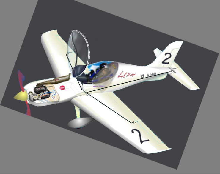
Just finished going through my Latest edition and yes, I was a little disappointed in the photo content. As mentioned, the cover was just a patch of blue with a GA plane doing things we are not allowed to do (how does the newstand public perceive that?) Then there is the 'centrefold(?)', a 60 year old GA plane with a lot of empty blue behind it? I guess the Antique Aircraft Association is going to give us equal space and put a Jabiru in their next centrefold ! Personally, I'm not a 'people' person, and tend to like looking at pictures of aeroplanes, but I guess it's good to show that there are people involved with flying, as such, I liked the shot of Ben McGuinness and his Waiex heading Arthur Marcel's article. This showed him and his aeroplane, not just the tip of his prop. I wont complain about the advertising as it pays for the magazine, and tends to show a wider variety of aircraft than the articles. I was a bit confused however by the small image of the silly convertible flying machine amongst the letters to the editor, try as I might, could find no letters, articles or comments regarding it? Just a page filler I guess? All this aside, I suppose we (I) really can't complain if we (I) haven't put in any articles ourselves....
-
While it is amazing just what will fly, the short answer here (as defined by what has been made so far) is NO, it will not fly, which is good as there is less chance of more aviation related sensationalism being hyped by the media. Observations; If the wing structure relies solely on the steel tubes in the wings, they will fold off before liftoff. If the wings are fibreglassed, as the tail appears to be, the total weight will be high enough that by the time the aircraft reaches liftoff speed (if attainable), the wings will fold of again. If being in India, there's a good possibility the engine is out of a Morris Minor, ie, will not reach liftoff. It is a pity to see so much effort go into creations with no real chance of succeeding, especially in an economic environment as theirs. Arthur.
-
I cant find one of my good drawings to show, but I will try to explain; This is a project I have on hold, that was to use a R503 mounted upright with the gearbox also upright, and having cheek cowls like a flat motor. On one side is the carbi's and filter(s), on the other side is the exhaust. These items are more or less in line with the prop shaft so the effect is quite neat. More of this project at; https://plus.google.com/photos/113292981019876413104/albums/5194978509871592929?banner=pwa I'll get back to it one day. Arthur.
-
Not quite sure I understand if this is to be a full VW, or a 1/2VW? Or is this the anticipated total cost? If it's a full 4cyl, with start and dual mags, it will be very heavy and as ugly as that black and yellow thing (sorry to the owner, but look at the front of that thing ) Next point, if it's to be a 1/2VW, you will be lucky to get 25hp out of it, really! Dave King and Brian Gabriel before him could both see the only way to go is a 2 stroke. You can probably get a reco'ed 503 cheaper than the VW(which will also be reco'ed), it will be lighter and it will put out 50+hp. It wouldn't take a lot of work to clean up the exhaust setup. The weight saving of a 503 would offset some larger tanks in the centre section to avoid CofG changes. I've recently been trying to test fly a machine designed for a 503, that was fitted with a Revmaster, it's not looking good. The motor feels like it's putting out about 40hp, and the aircraft came out a bit heavy. The net result is minimal performance. Just found another two stroke Hummel here in Oz; http://www.lmacrc.com/Photos/2006/Home Built.htm I think some large side cheeks could hide the exhaust on one side, and the carbi's on the other side...... Dont get me wrong, the half VW Hummels are out there and working, BUT, the good ones have no electrics, are hand start, and take off from 1000 ft of concrete. I rest my case; Arthur.
-
Another impossible dream. Maybe not.
pylon500 replied to Deskpilot's topic in Aircraft Building and Design Discussion
Can't say I've actually looked up what this is (I'll get around to it), but just from a basic aerodynamic layout,it looks OK. Some points though, yes I agree with the others re the billy cart steering. I built a trike many years ago, but as a normal aircraft pilot, the idea of billy cart steering didn't appeal, so I made a pedal arrangement that pulled from the bottom of the pedal hence turning the nose-wheel fork in the right direction. As a bonus I mounted an inverted T shaped item just in front and above the tire, held off the tire by a large spring. Thus if I pressed one pedal, it pulled the fork to steer, if I pressed both pedals (against the spring) the T bar pulled down onto the tire, giving me brakes! Now, other points; Had you thought of a tail dragger? Symmetrical section, pro's and con's, no pitching moment (good); Flies at higher angle of attack (how much rotation clearance do you have?); Thicker (how thick do you need?) With the area your looking at, I would stick with a semi lifting section, look at a Foxbat section, has good stall habits, low pitching moment and a bit of thickness. Power plant setup, a long toothed belt like that will have a lot of 'whip' which needs to be controlled, and if running from a two stroke, will need reduction, so how about an upright motor behind you on the bottom using a toothed (or poly V) up to the wing with twin sprockets on the same shaft running chains in tubes to the prop shafts? Sounds ancient, but remember chains have less losses than rubber belts, and you've absorbed the impulses back at the reduction point. Looking at your 'cutaway' of the tail, why bend or break the main tail spar, and then only support upwards with cables? Remember, there is a download on a tail inflight and the joining brackets to hold angled tubes would be wasteful in weight terms. Maybe a tail half up the fin with cables top and bottom Still don't see the point in the angled tip fins? Would be better to hang the ailerons on the lower wing, less complicated to connect, and just use end plates for tips. Is the prop spacing to get them in clean air, or just look good? I know you don't intend to get asymmetric thrust, but if put as close to centre as possible, is lighter and more controllable if you do lose one. You also have not shown any drag (thrust) bracing within the wing to hold the props Any intention to wire brace the wings, or just use big tubes? The end fins wouldn't do anything to support the wings so you need a strut or wires (or big tubes, I'm talking around 4"Ø here) Do you really need that square tube for the nose? Just continue the twin tubes all the way, have a look at the Mitchell P-38. Please don't think I'm trying to shoot you down. I think your onto something, (although I designed something similar many years ago, look in top right here; https://plus.google.com/photos/113292981019876413104/albums/5212775815502683841/5213148201835122130?banner=pwa). I'm in a position that once I've seen something, then I can see where improvements could be made. Arthur. -
Another impossible dream. Maybe not.
pylon500 replied to Deskpilot's topic in Aircraft Building and Design Discussion
OK, the concept shows promise. Tend to agree with others that the props are not going to be in a comfortable position. Could they be pushers behind the top trailing edge? Point 2, a V tail will have a lot of trouble trying to handle asymmetric thrust. Also at that short a wingspan, the V tail will give you a lot of adverse ROLL with rudder application, an inverted V tail can solve this. Personally, I would go with a flat tail with twin fins, or a simple T tail. Does the end plate joining the wingtips really serve any purpose? Short wings like that could be cantilever, and simple tip plates will give you apparent extended span. Would be a lot less complex with a single pusher, but I see we're doing this just to be different..... If we want LITTLE, have a look at this; This was hard to find, but have a look here;http://chuckisawesome.org/?p=996 Arthur.
-
As a previous glider pilot, I am also not a fan of Frieze ailerons for the drag reason, and also not a great fan of flaperons because of the adverse yaw problem ( he says while spouting praise for the Foxbat ?!?!) so we are on the same page.
-
This mainly applies to faster aircraft when flying at low speeds, like take off and landing. While twist (washout) can have some structural problems at higher speeds, this doesn't really apply to us, so we are better off just having a bit of twist. It's also lighter than flaps. No, not really, the gazelle system is more akin to what Junkers was using back in the 30's. The AN-2 uses a sort of Frieze/Fowler type flap and aileron, much like the Foxbat uses today. For the picky, the more 'remote' the hinge point is, the more Fowler it is. The real difference is more to do with the underside of the trailing edge of the wing in front of the surface, if it's square like a Cub or Spitfire, it's a Frieze. If the underside is rounded to allow smooth airflow up over the surface, like the flap area on a Cessna or the Foxbat (regardless of hinge point), then it's a Fowler. (That's my view anyway..) Arthur.
-
In lay terms, if the wing stalls in the middle first, then the aircraft is being supported by it's wingtips, which would be stable. If the wingtips stalled first, chances are one would stall before the other, making that wing drop and roll you over on your back. Not what you want close to the ground! Various means are used to ensure the centre of the wing stalls before the tips; 1. Washout built into the wing, which is twist along the wing giving the tips less angle of attack than the centre. 2. Change of wing section type along the wing, where the tip section is given a higher lift coefficient than the centre, which means the centre looses lift before the tips. 3. Aerodynamic devices added to the wing to either maintain lift to a lower speed towards the tips (cuffs, fences, vortex generators), or other devices to actually destroy lift near the centre at low speeds (stall strips). 4. The use of flaps will have the same effect by changing the angle of attack between the flapped area, and the non flapped area. With all this in mind remember, if you are close to the stall and/or at a high angle of attack, use of the ailerons will usually cancel the effectiveness of all these devices, and you will end up on your back again!! How to create and use ailerons or flapperons at low speed is another lesson........ Arthur.
-
Sleepy Air Canada pilot thought Venus was a plane
pylon500 replied to fatmal's topic in Aircraft Incidents and Accidents
Interesting to see that they are allowed to sleep for 40 minutes.....? "This is your Captain snoring, ZZZZZZZZZZZZZZZZZZZZZZZZZZZZZZZZZ" Yeah, I know it was the FO.. -
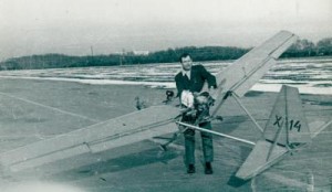
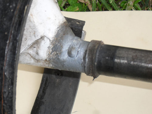
G'Day Ross, You are right in that there was a weld repair at the point the axle broke. Why it was re-welded is unknown, nothing in the logs, but it had been welded on both sides, see photo; This is the other side and was only found after the accident. The reason I comment is that about 20 years ago, we had the exact same failure occur on our club GR582. Examination of the axle showed that it had been cracked for some time, we suspected since new, but being on top of the axle, it was being held closed by the weight of the aircraft. The crack propagated over the years until a slightly heavy landing caused it to fail (same as mine). That GR582 was serial #5, mine is #83 and still had the thin wall axle and no solid plug inside? Some axles look solid, but actually have blanks welded on the ends (like mine). Something to watch for...... Arthur.
-
Another point worth inspecting is the base of the wheel axles. Remove the wheels and look VERY closely at the top of the axle between the bearing collar and the welds to the legs. Dont get me wrong, these are great planes, but this is something to watch for... Arthur.
-
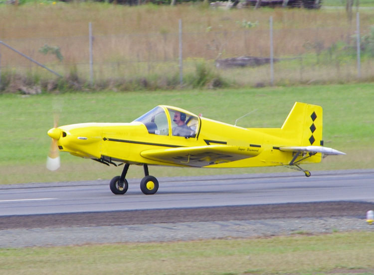
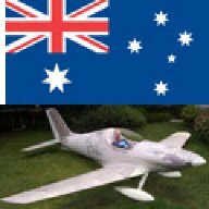
Looks like we're trolling at the same time, just looked at the picture and thought "looks like a Renagade", did a quick search and got, http://www.regosearch.com/aircraft/au/LFZ