IBob
-
Posts
3,070 -
Joined
-
Last visited
-
Days Won
26
Content Type
Profiles
Forums
Gallery
Downloads
Blogs
Events
Store
Aircraft
Resources
Tutorials
Articles
Classifieds
Movies
Books
Community Map
Quizzes
Videos Directory
Everything posted by IBob
-
A little light relief (and a whole lot of thread drift). This remains one of my favourite Monty Python sketches of all time. And the phrase that sticks in my head (and could be applied to all things, aviation included) is at 03:15.
-
Nev, someone in the S Island here is now manufacturing a louvre setup. Initially for the Sav, I think, but no doubt adaptable for other configurations. A mate who flies a lot more and often higher than I do recently sent me pics, and it looked like a really nicely designed and engineered thing.
-
Skippy, I'll take some measurements when next in. I cannot take any credit for the choice or the installation: I just followed the instructions and equipment that came with the kit (which included both the coolers) plus the excellent build pics supplied by the Oz agent at the time, Reg Brost. Points of difference between my aircraft and yours would have to include that my fixed pitch prop is set up for the usual compromise between takeoff and cruise. I typically cruise at 5000RPM and 85kts. And while the Savannah will go quicker, as a draggy aircraft with a fat wing, it doesn't really want to. All of which is to say that your engine is almost certainly working much harder than mine in cruise and so producing more heat.
-
It'll be interesting to see where you arrive at with both resizing and repositioning of the cooler, Skippy. The Savannah has the cooler at the pointy end with it's own air intake and a pronounced lip under the rear cowl to reduce exit air pressure. I can't tell you the size of the cooler (I can measure it when next at the hangar, if you wish), and obviously we don't have your elevated temperatures here in Nuzeelun. But in winter I'm flying with about 2/3 of the cooler blanked off, in summer 1/3, and it still takes a sustained climb to hit the recommended 100'C mark.

-
Thanks for that Skippy. A couple more questions: What RPM do you cruise at if in cruise mode? What RPM do you get if you give it full throttle in cruise mode? You may have already covered all this earlier in the thread or posts, if so, apologies. It's probably I also need a lesson on CS props???
-
Can I belatedly ask why you are going for the extra large oil cooler, Skippy?
-
What Skippy said. Any transparent or semi-transparent bottle of reasonable thickness and with a reasonably robust screw top. The Sav one is really tucked away behind the oil tank*. Attachment is a very simple bracket riveted to firewall, bent out at the bottom to support bottom, bent out and scalloped at the top to steady the bottle neck, and with wings at the sides with holes: cable tie goes through holes to hold bottle back against bracket/firewall. *So tucked away that I had to fill it via a thin pipe inserted in the engine reservoir overflow.
-
You do really nice work, Marty. My radiator bottom corner initially touched the cowl on the port side, I was able easily to pull it up at the rear to give good clearance.
-
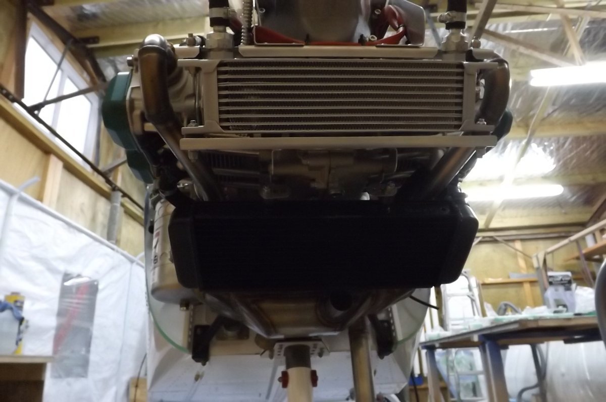
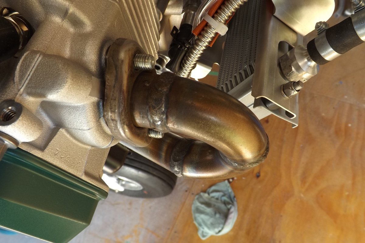
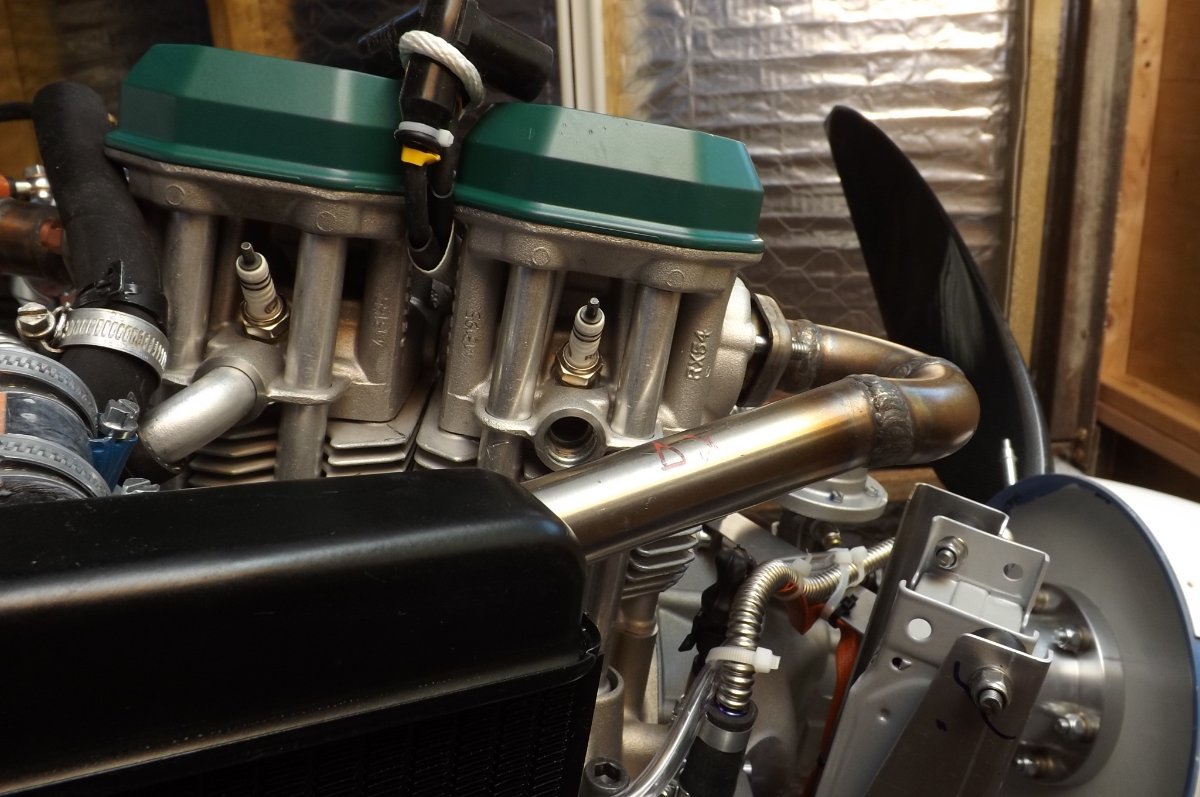
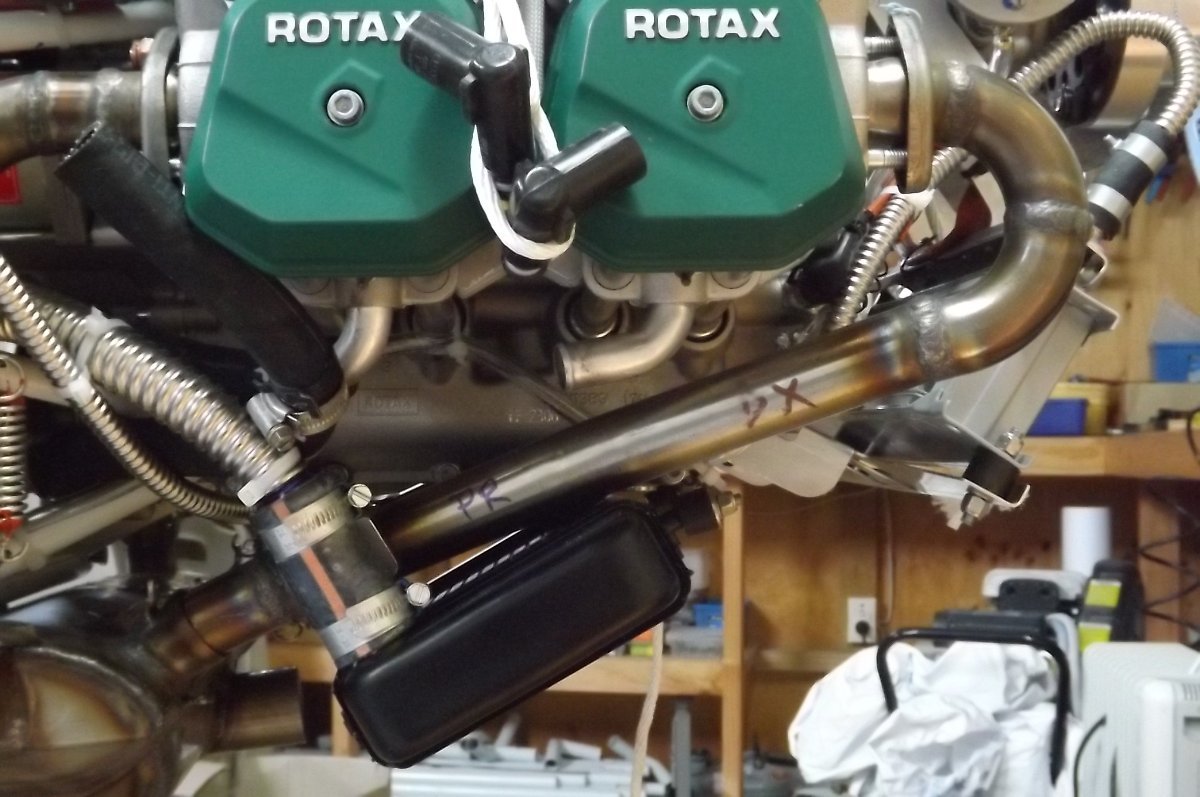
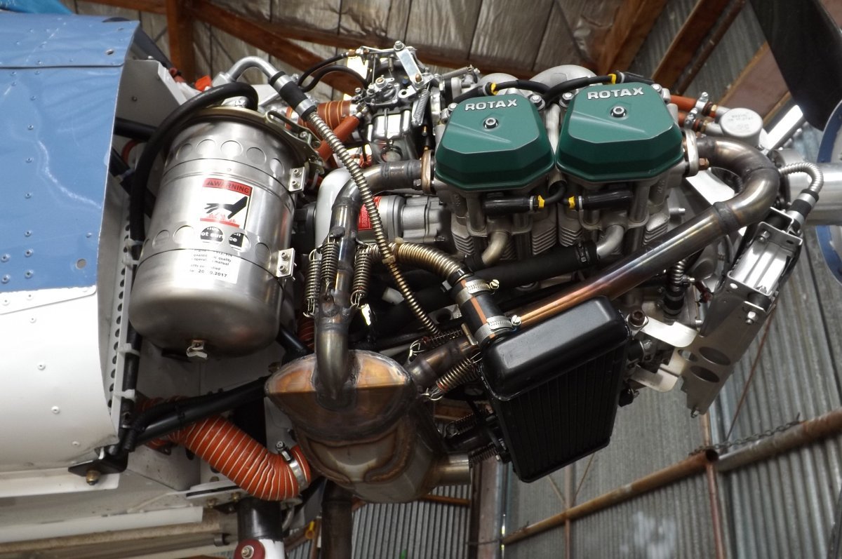
Partial glimpses here taken during build, when I was trying to figure out why my exhaust pipe wanted to occupy the same space as the cylinder coolant plumbing..............:
-
Hi Marty, the Sav has a bracket from the gearbox side bolts to shock mounts to the oil cooler top. This is a fabricated bracket that picks up the side bolts and has a crossmember across the top of the cooler. The bottom of the oil cooler is shock mounted to a bracket made in the same way that goes back to side bolts under the engine. That point also serves as the mounting point for the top of the coolant radiator, which is also shock mounted. The rear of that radiator is pulled up to the underside of the engine by a tie. I'm sorry I don't have a clearer pic.
-
The popular 1930s (?) book, The Professional, is intended as a humorous address... but also contains all the solid practical advice you'd ever need to site and construct a longdrop. Or a row of them (the family 3-seater etc). As this is what the book is all about. Factors when siting included putting it out past the woodstack: since the ladies don't like to announce where they are actually going, they can say they are just going out to get some wood. and that way the woodbox always stays well topped up. Clearly you missed the opportunity there, Marty......but you may still find you are required to add soundproofing....)
-
It grew rockets???????????????????
-
OME I have ridden to 13'000ft over Florida in Mr Douglas, a DC3 with tinted windows, 8 track stereo...and yes, shag-pile carpet (though I can't vouch for the fire rating). Where we all got out.......well, all of us except the pilot. The jump itself was a shambles: we all had green cyalumes taped to our rigs, but nobody had thought to equip the base (centre jumper of the proposed formation) with something of a different colour. So the sky was full of little green lights, all wandering around trying to figure where to aim themselves, before finally heading off for an empty bit of sky. But I wouldn't have missed it for worlds.......)
-
Despite the carpet in my kit being precut, fitting it wasn't the pleasure I thought it would be. I was using Ados F2 contact adhesive from the can on the hull, and from spray cans on the carpet. I'm a fairly tidy worker, but it was messy, with overspray finding it's way onto me, the floor, and anything in the vicinity of the spray area. It had the usual contact adhesive problem that you only got one shot at positioning the carpet piece. And I went through 2 cans of spray with only half the job done. For the second half, I hit on a better system: I thinned the can of F2. This allowed me to spread it on both hull and carpet with a brush, slowed the drying time, and allowed the piece to be peeled and repositioned if not properly placed. This was a huge improvement. The bond is not as strong as using straight F2, but is more than adequate for attaching carpet: 3 years on, nothing has come loose. For thinning I used what was to hand at the time: 2 way paint thinners. The fumes were awful, fortunately I have a good spray mask. I now see that Ados do a Solvent N for thinning and cleaning. In the next life I'll be using that......
-
Your Mk1 version works fine here, Mark. I think the key thing is that the inner latching works need to be be completely free moving and free of any possibility of binding.
-
A simpler option (certainly when building) would be to remodel the bracket to tilt the stick forward a bit. It would mean moving the pivot point a bit forward and adjusting the sweep and position of the quandrants to ensure correct mixer movement, so would mean making new brackets. But it shouldn't be hard to sort out.* The reason I like that option, and the reason I stuck with just modifying the stick Is that, apart from stick angle, the mechanism is simple, safe and works very well. The innards do need to move freely, almost rattly loose, as the latch mechanism relies on the spring under the button. So the usual thing when setting flaps is to give the stick a wiggle to make sure it is solidly latched. I have also seen situation where the rubber grip has moved up on the handle and is starting to foul the button, so the grip needs to be well anchored. *Maybe a little job for Mark..........in his spare time.....😆
-
Shafs, I'm of average height, so seat fairly far forward, and I found pulling full flaps on the standard lever very clumsy: instead of pulling up on the handle, the last notch was pulling back into the stomach. That and incident reports where improperly latched flaps have caused a few frights and sometimes major damage, and I decided I needed to do something about it. It took a while to decide on how to do the internals, but turned out to be very simple, just needs to be made fairly precisely. I had help with the fabrication, my DIY abilities come nowhere near welding stainless. The angle in the shaft is just 12degrees, but for me it has made a huge difference. PS note also Mark's excellent 3 position flap bracket in place of the standard issue 2.
-
Looking really nice, Mark!
-
And here is a the A/B/C pinout: https://duckduckgo.com/?t=ffab&q=pinout+of+rotax+oil+pressure+sender&atb=v356-1&iax=images&ia=images&iai=http%3A%2F%2Frepairguide.autozone.com%2Fznetrgs%2Frepair_guide_content%2Fen_us%2Fimages%2F0996b43f%2F80%2F20%2F27%2F4c%2Fmedium%2F0996b43f8020274c.gif
-
Okay, so I found this, which suggests that they are using a 2 wire current loop setup: https://duckduckgo.com/?t=ffab&q=pinout+of+rotax+oil+pressure+sender&atb=v356-1&iax=images&ia=images&iai=https%3A%2F%2Fdesk.zoho.com%2FDocsDisplay%3FzgId%3D714941653%26mode%3Dinline%26blockId%3D1hflqdbff7005142a40f9ac47410e66c421a2 It says that Pin A = n/a Pin B = 8-24VDC (12V in our case) Pin C = Signal And here is how it is wired to the gauge: https://duckduckgo.com/?t=ffab&q=pinout+of+rotax+oil+pressure+sender&atb=v356-1&iax=images&ia=images&iai=http%3A%2F%2Fwww.aviasport.com%2Fimages%2FConexiones_OIL_P_4_20_57.gif Danny, I found that by searching 'pinout of rotax oil pressure sender'.
-
Agreed, Nev: if buying from a transducer manufacturer or supplier, it would all be on the data sheets. But Rotax have gone to their own numbered part (albeit manufactured by others) so unless we have a non-Rotax part number for the unit, we're guessing a bit. Unless Rotax have published details somewhere.....they may have.
-
Danny, as I recall, my engine came with the sensor/sender (we just used to call them transducers) fitted, with the plug and cable attached. The cable would have been marked, so no need to meter through to the plug pinout. If all else fails, maybe you could find someone with a new uninstalled engine, and get them to meter out the cable/plug for you.
-
That's correct, Skippy. Think of it as a diaphragm, with one side to atmosphere, the other to oil (or fuel) and it is measuring the deflection in the diaphragm. The key element is that oil pressure is atmospheric + pump pressure, so you are measuring that against atmospheric pressure. So as you climb, the atmospheric pressure should decrease on both sides of the diaphragm, but the differential pressure (and diaphragm deflection) remains the same = accurate reading. If, however, the atmospheric pressure falls as you climb on the oil/fuel side, but remains at ground level pressure on the other side (due to being sealed) then you get an increasingly inaccurate result.
-
Danny, these sensors are differential: they should measure the difference between the oil (or fuel) pressure on one side, and atmospheric pressure on the other. Your oil pressure is atmospheric pressure + pump pressure, and is measured against atmospheric pressure. So as you climb, the atmospheric pressure falls, but the differential pressure remains the same, so you continue to get an accurate reading. But If the sensor is sealed on the atmosphere side, then the atmospheric pressure is falling as you climb on the oil pressure side, but remains the same on the 'atmosphere' side. So you get an increasingly inaccurate reading. And in the case of Skippy's fuel pressure reading it would make a huge difference.
-
Ah right, Skippy, that would be much more of an issue: the oil pressure unit is 0 to 10bar, mine sits 5 to 6, but the fuel pressure is 1/3bar or less, so if the unit is not correcting for altitude, you would see little or no fuel pressure at 10,000'. I have seen the same problem now, twice, with fuel pressure steam gauges, where the builder has not removed the shipping plug from the gauge body.