IBob
-
Posts
3,072 -
Joined
-
Last visited
-
Days Won
26
Content Type
Profiles
Forums
Gallery
Downloads
Blogs
Events
Store
Aircraft
Resources
Tutorials
Articles
Classifieds
Movies
Books
Community Map
Quizzes
Videos Directory
Everything posted by IBob
-

Circuit Issues at uncontrolled aerodromes
IBob replied to kgwilson's topic in Aircraft General Discussion
Brendan, I would say make sure you have a radio that works well in your aircraft, and learn to use it to give and receive clear communication. (We all like to think we do that, but some mumble and do not enunciate clearly, and some speak in a rapid monotone, presumably thinking that makes them sound cool and professional.) Test it by asking for radio checks: some owners fit handhelds, and while they may work okay in some airframes, it's clear that they don't work well in others. If necessary, get whatever you can to improve your own hearing inflight: I have Lightspeed Zulus, which are a major improvement over passive headsets for me. Learn to set and use the squelch on the radio: it's not a set and forget thing, if set too high may cause you to miss calls. And get ADS-B. It won't necessarily be used much to locate you in circuit, but what it WILL do is alert others to the fact that you are there. -
Hi Bryan, I believe ICP pre-adjust the angle on the ring mount provided, with packing washers at the silent mounts. So if you look at those washers at the 4 mounts, they are not evenly distributed. But that will not be any help to you if you are using a different mount. The aircraft with standard wheels sits with the upper rear fuselage horizontal (or parallel with the ground). It says in the manual 'Inclination of axis of propeller to upper part of rear fuselage : 0'-2' down.' So that is your reference in that axis: the plane of the upper rear fuselage. And the 2 plus/minus 1' right is from the centre line of the fuselage.
-
Circuit Issues at uncontrolled aerodromes
IBob replied to kgwilson's topic in Aircraft General Discussion
What Nev says. I don't claim much experience or expertise, but I've had plenty of time to think about all this, with one tragic accident and further events as wake up calls. One thought that has exercised me is a strong sense that these things would be less likely to happen to the truly seasoned professional pilots on the airfield. And it seems to me a significant part of that must be more complete situational awareness. So I have been doing what I can to improve that for myself, with an ongoing focus especially on radio. As I mentioned above, we saw a considerable improvement in local radio work following the midair. For me at least, that has made a considerable difference. During a recent user meeting we had a visit from the CAA, who told us they are going to be looking a bit harder at our end of aviation. Last year they released an educational module on overhead rejoins. I have my own misgivings about aspects of that. But the next module is to be on radio work, with the aim of improving the general standard. I would welcome that wholeheartedly. -
Circuit Issues at uncontrolled aerodromes
IBob replied to kgwilson's topic in Aircraft General Discussion
I don't have anything like your depth of experience, KGW, but I'm not sure I agree with you: Since the midair here (double fatality) there has been a lot of conversation and thought as to how to improve the odds. And for me, fresh urgency in that when, a year later, I had a near miss of my own on departure. It seems to me that none of the tools at our disposal........see and avoid/radio/ADSB......... are anything like perfect in terms of collision avoidance. So I believe our best chance lies in using all these things, appropriately and where available. Certainly there has been a noticeable improvement in local radio work since the midair, which I find a great aid to my situational awareness. And I can say this: on the two occasions I have been cut off on base by aircraft on finals (though not too close, thankfully) neither had made any radio call. And for my near miss on departure, which did involve radio calls, my contribution was to hear and discount an overhead rejoin on the incorrect assumption that we wouldn't be requiring similar air space. So yes, radios. I very much believe in radios. -
Circuit Issues at uncontrolled aerodromes
IBob replied to kgwilson's topic in Aircraft General Discussion
I don't think it ever has been, Turbo. I'm talking GA and microlight here, I have no idea about the rest. -
Circuit Issues at uncontrolled aerodromes
IBob replied to kgwilson's topic in Aircraft General Discussion
Thank you Garfly. And that report points to the other elephant in this room: the time required to recognise a threat then take any sort of effective action: 12.5 seconds, folks. As I recall for our midair here, it was estimated that at the -12,5sec point, the other aircraft would have been about the size of a fly on the windscreen....( -
Circuit Issues at uncontrolled aerodromes
IBob replied to kgwilson's topic in Aircraft General Discussion
Turbo, I'm not for one moment suggesting our legislation and habits are better than those in Australia...or anywhere else, come to that. As you will see: Recommended circuit practise for unattended airfields in NZ is one call downwind. I also call when on finals, and many pilots do (despite the pearl-clutchers worrying about us bunging up the airwaves). But Radio is not mandatory or required in uncontrolled airspace here........! -
Circuit Issues at uncontrolled aerodromes
IBob replied to kgwilson's topic in Aircraft General Discussion
A couple of things: 1. It seems to me there is a whole 'king's new clothes' aspect to this business of see and avoid. Yes, we know we 'should' be doing it, and we read the instructions accordingly. But how many of us actually practise it? I'll even turn the question round the other way: there are endless YouTube clips of pilots at all levels of experience flying. If anyone can show me footage of a pilot actually conducting constant routine visual scans as recommended, please post it here. 2. A fellow aviator here alluded to a fatal midair at our local airfield 3 years ago now. Part of the evidence in the resultant court case (since abandoned by CAA) was a report written by Dr T J Lambert, an expert in human vision. It deals, in very readable terms, with the realities and limitations of see and avoid in general, and then in the context of that accident. So far as I know, it has not been released into the public domain, but I am trying to find out it if it can be made available. It spells out just how unrealistic some of our expectations may be, and I think we need to realise that. -
Good point, Blueadventures. And I can see how that would constitute 'best practise' too. It would be interesting to know if it makes any practical difference in this particular case...and I can't think of any easy way to determine that. What we do have is a lot of aircraft not plumbed that way (I went back to the build manual) and apparently not suffering any ill effects. But that doesn't rule out the possibility.
-
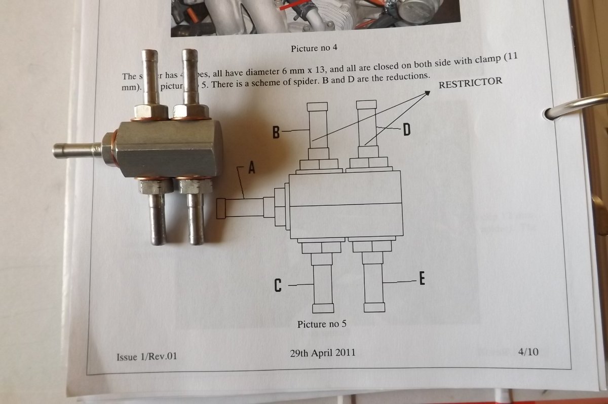
See my earlier post: the effect in this case is negligible, put the manifold where it suits you. Marty, you're right, you get the same pressure regardless of hose length....until you open the end and get flow. then you get friction losses in the pipe, resulting in reduced pressure and flow the longer the pipe.... so........... Spacey, you're right, but its a a matter not only of pipe length but (air or fluid) velocity. Here you have very small pipe lengths and low velocity, so the difference in pressure drop in this case is negligible.
-
Surely does, BrendAn..............the need for speed.................)
-
Meanwhile, in Thailand, despite the unavailability of Zvezda engines...........:
-
You're not wrong, Nev. Though in the above context, the radiated heat can be reduced or eliminated by positioning or shielding, since it is line of sight.
-
Yep. And the more I think about it the less sense it makes to have the manifold etc plus all the split off pipework sitting up there in the hotspot. The alternative mentioned above has just the minimum...feed to and from the mechanical pump....situated up there.
-
Blueadventures, I think we're all doing it because that's how we all do it. In broadest principal it makes sense to have shared flow systems physically ballanced. And certainly for high velocity things like air and exhaust, this is so. But for this instance, I just dialled up the online pipe loss calculator. And for a cruise flow of 17lph and carb feed lines of 150mm and 500mm length respectively (I'm not at the hangar, so guessing here) the pressure loss is approx 0.003PSI different between the two sides. That is 1/700th of the minimum fuel pressure mandated by Rotax to run this engine. So, yes, if you ever get to the situation where the carbs are competing for fuel delivery, then you will get slightly uneven delivery. But if you get to that point, something is horribly wrong with the system elsewhere anyway. And here's a vaporlock afterthought: In a land/shutdown/hot restart/takeoff situation..........maybe it's not best to have all that heat absorbing and transmitting ironmongery sat right on top of the engine??????
-
And while we are on it: can someone point out to me where in the 912 manual it says the fuel lines to the carbs need to be identical in length? Certainly in the fuel system section it gives a set of coordinates for the fuel manifold as set out by Rotax....but if there is any note saying these coordinates are important, I haven't found it yet. I'll stick my neck further on the block: my build was done using, amongst other things, build detail pics from the then agent, which I found invaluable. Following those, my manifold is mounted where the LH upper engine mount meets the firewall, which gives a short run to the LH carb and a a longer run to the RH. And that seems to be working fine, with smoothe starts and running in all modes.
-
Yep, I'd agree there. Here is what ICP supply:

-
Sorry, wrong link, should be: https://www.atsb.gov.au/sites/default/files/media/24363/aair200700054_001.pdf My reading of that ATSB report is that they examined the crankshaft remains, using various methods. They verified that the alloy complied with the stated Rotax spec. They did not find any evidence of any manufacturing fault that may have contributed to the failure. They made no analysis of the design itself, which presumably was outside their remit.
-
Nah.........just an alternative sort of tie-down.........)
-
I have the best set of cold chisels! They're actually Sears Roebuck 'Craftsman' wood chisels. Made out of some super tough stainless material: impossible to sharpen to anything like a wood shaving edge, but otherwise totally indestructible, I've been dealing to rock and concrete with them for 40mumble years....)
-
With due respect to your prof, I'm not at all sure that is universally applicable. I did a lot of work on industrial regfrig, boiler, timber kiln, hot water systems etc. This involved monitoring, logging and displaying as required all sorts of temps, pressures etc. We used to say that faulty data is worse than no data, in that it can lead you to faulty conclusions. And for the same reasons, when presented with stats, I have always wanted to see the raw data, not the data as it has been interpreted by somebody else.....
-
Rotax 912uls ignition pinout
IBob replied to danny_galaga's topic in Instruments, Radios and Electronics
Each module has it's own soft start input. But those have probably been joined, to make one wire that goes to the starter solenoid. Or that's what I did. -
Rotax 912uls ignition pinout
IBob replied to danny_galaga's topic in Instruments, Radios and Electronics
Heavy Maintenance Manual section 74-00-00 Page 29, 912 'New Model' ignition circuit diagram. Shows plugs, sockets layout and wire colour coding, with coding key at lower LH. The missing wire goes to the kill switch. Cannot tell you what sort of connector, Mark will know. -
Nice work, Marty. FWIW both my port lower coolant hoses pass through the angle of the lower engine mount, rather than under it. As I recall, I adjusted (rotated) the position of the fittings on the coolant pump to direct the hoses through that gap. It is easily done with the housing out using moderate heat. I mention that only as it may give you a bit more clearance under there. (PS: but whatever you do, don't mess with the fittings in the cylinder heads. They use a high temp Loctite and if you get seepage there it is a b*****d to fix!)