IBob
-
Posts
3,085 -
Joined
-
Last visited
-
Days Won
26
Content Type
Profiles
Forums
Gallery
Downloads
Blogs
Events
Store
Aircraft
Resources
Tutorials
Articles
Classifieds
Movies
Books
Community Map
Quizzes
Videos Directory
Everything posted by IBob
-
Glen, I know nothing about Jabiru engines, and just a bit about the Rotax 912 since I own and maintain one, so have a particular interest there. I do understand the importance of the float bowl vent, as providing appropriate float bowl pressure (in the Sav the vent/s are plumbed into the airbox downstream of the filter, which makes sense). I am fortunate that my enrichment (aka choke) has a free action, and shuts positively as soon as released. I hadn't thought about carb heat, but try not to make that a set and forget thing: I can set various degrees of that, so tend to return and adjust it when in use. Having said all that, it is perhaps 800m of taxiing from touchdown to my hangar and any time I have pulled the plugs they look very rich. However, my fuel consumption is certainly not excessive and the thing has run like a dream from new, so I have just assumed that the Bing setup runs rich near idle. You say the Jabiru was about right, now rich after LCH? I'm not quite sure what you mean there???
-
All the best with that Kgwilson. And I wasn't referring to any post you may have made.
-
Before moving onto Holden........I would like to say how much I like the Rainbow Aviation approach to troubleshooting Rotax engines, as set out in their excellent carburettor functional descriptions in the links posted above. They take a 2 step approach: 1. Find out what has changed since the engine came from the factory. 2. Put it back to how it was when it left the factory. Which might sound glib or simplistic, but not so long ago we had someone in another thread here experiencing erratic or rough running problems. And when last reported, they were off to alter the carb needle settings...........(
-
 That article referencing the Australian dark sky takeoff accidents study makes for sobering reading: "Interestingly enough, investigators found that in every case the doomed aircraft struck the ground within 3 nm of the airport, and within one minute of becoming airborne. In 87 percent of the crashes, the aircraft impacted to one side of the extended centerline with wings showing little or no bank at the time of impact. In every crash, the wreckage indicated that the aircraft was under control at the time of impact. Specifically, the investigators noted that the aircraft damage was consistent with the pilot being unaware of any unusual attitude."
 -
RFGuy them's the numbers........however with that fat wing and various other gear hanging out in the breeze, the reality is you'd need to be doing something well past radical to reach 124kts. As most owners will agree, the Sav is happy at about 85kts. Anything much above that and there is very much the sense that you are pushing it..........)
-
Skippy, I think part of the problem is that we label this particular control as a choke, because that's the sort of function it performs, and that's how we are used to thinking of it. And I am no different: mine is labelled 'choke'. But as others have stated here: 1. It is actually a starting carburettor. 2. The throttle also needs to be fully closed for it to function (because it is this full closing of the throttle that provides the necessary 'choking'.) Here is mine.....labelled choke:

-
Skippy, here are two excellent detailed writeups, with illustrations, on the Bing64. The first covers the operation of the main carburettor. The second covers the operation of the starting carburettor. https://electricmotorglider.com/2017/02/01/bing-64-cv-carburetor-part-1/ https://electricmotorglider.com/2017/03/01/bing-64-cv-carburetor-starting-carb-part-2/
-
Go for it, Gary......and don't forget to post pics of air under the wheels.......)
-
The story does just seems to get worse. As for nobody speaking out: I have wondered if it might in part be a reluctance to be the first to speak out. I was thinking of the famous B52 crash, where the pilot had been variously bending and breaking the rules for years, but nobody (apart from one man who died with him) was prepared to do anything about it. Ridiculous as it seems, maybe it's a sort of male gungho chicken thing, where speaking up is chickening out.......(
-
It certainly works very well for me, RFguy: in 230+hrs the only time I have not had near instantaneous and smooth starts, was due to stale fuel after lengthy Covid lockdown. So much so that if I ever start to get less clean starts, I will be looking for the problem. Further to all this: a while back, someone posted a link to a very good video on this carburettor. I did watch it, but cannot now recall where it was. Anyone???
-
I suppose we are all talking about the same carburettor here: the Bing 32???
-
Bleuadventures Blueadventures, I don't think that's quite right either: pulling the choke rotates a disk that exposes one of two different sized ports. A full pull is a big port, a partial pull is a smaller port. So a partial pull is still giving some enrichment, I would think (always assuming the main throttle is fully closed).
-
Skippy, you may well be right. No doubt ambient temperatures have a bearing, and they are normally not low here. All I know is that I have evolved a routine that sees near instantaneous clean starts with a fairly prompt transition to an initial idle of 2200RPM, choke off, during which the engine neither labours nor overspeeds. I say fairly prompt as it is several seconds before the timed ignition goes to fully advanced (at which point the RPM rises). As a side issue, it is worth checking the idle speed (throttle stop) and the idle mixture screw settings, as set out in the line maintenance manual under basic throttle adjustment. These are very quick simple adjustments. My new engine had the throttle stops set correctly, but the idle mixture screw settings were only approximate, and not identical. I have also seen a new 912UL with various idle and running problems, where the problem was incorrect setting of one carb needle. Which is to say that whoever does the Rotax carb settings is not bullet proof.
-
Skippy, that's odd: when I pull the choke button on the panel, it turns a little disk in the internals, exposing one of two enrichment ports. I'm pretty sure it does nothing whatsoever to the main butterfly.
-
Skippy, congratulations! As for the choke.......whether it is lockable or springs back, I am ambivalent. Since I only use it at starting the 912 and almost immediately let it go, and since it does not work once you begin to open the throttle, I cannot see a reason to have it lock on. But quite probably others have different needs.
-
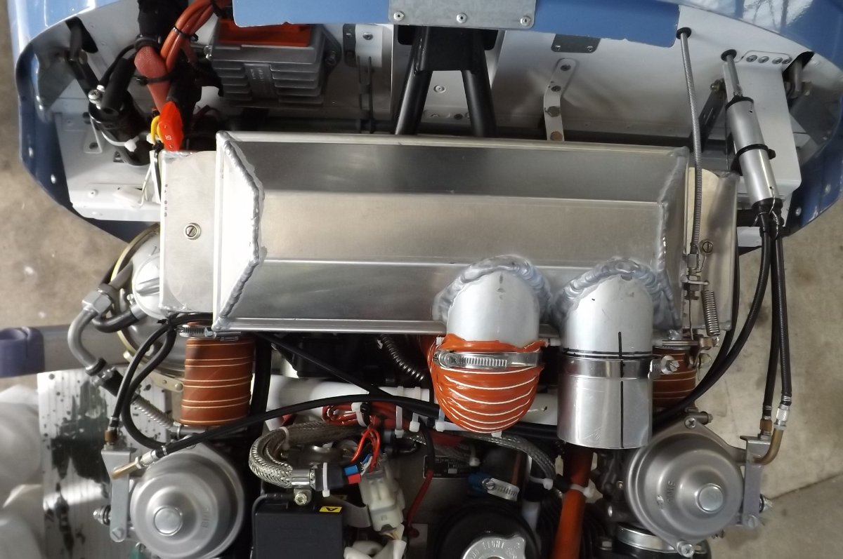
Blueadventures, I believe the throttle bar stop may go some way towards maintaining carb synchronisation. I have the standard setup, with two cables coming from the quadrant bar to the two carbs. Initially, as this bedded in, and as expected, the carb sync required periodic minor adjustments. But since approx the 45hr mark, no further adjustment has been required: I still check it periodically, but it will be almost 200hrs since I last adjusted it. I put that down to careful routing and securing of the cables and the throttle bar stop, which prevents the carb arms being pulled beyond the carb arm stops. And I would count it as one of a very small handful of worthwhile improvements to the Savannah build. The Savannah throttle bar has a centrally placed quadrant, presumably for those wishing to put in a centre knob throttle, but otherwise unused. This comes back and strikes a block of MDP, cut to thickness once I had everything else in, and riveted to the firewall. In the pic you can see the MDP block, it is white and just to the right of the voltage regulator, with the unused quadrant resting againts it.
-
CScott and Skippy....no disagreement with any of that! And no reason for a newer 912, properly installed and wired, to be hard starting. However, the older ones without the timed spark retard could be nasty: supposedly the spark advanced once the engine reached 650RPM, but the crude circuitry of the ignition module measures that in an odd way, and having seen them 'spit back' on many occasions, I'm not convinced it does it well or accurately. The newer modules have been a huge improvement. At the other end of the process, I get clean shutdowns too. I fitted a stop at my throttle quadrant bar, so that the throttle can be pulled back quite firmly without risk of bending the carb throttle arms, which are light in construction. At shutdown I first go to 3000 and run a mag check (not a very demanding test with warm modules, just a habit I picked up from another flier), then back to about 2000RPM. Then two fingers on two ignition switches, pull back firmly on throttle and switch off ignitions promptly, 1 then 2 as soon as RPM falls. This almost always gives me a clunk-free stop. A lighter prop also helps in this, though mine is a 70" Bolly, so not particularly light.
-
Hi Supacat, and congrats on your purchase. It's a great machine! FWIW: The S comes with multiple mounting holes for the rudder pedals, suggesting they can be moved forward. Note however that the S has a redesigned fuselage, so it does not necessarily follow that the rudder pedals can be moved in the VG. You would need to look at available space etc. Moving the pedals would require replacing or reworking the nosewheel linkages. You would also need to look at whether the rudder cables would adjust, or need modifying or replacing.
-
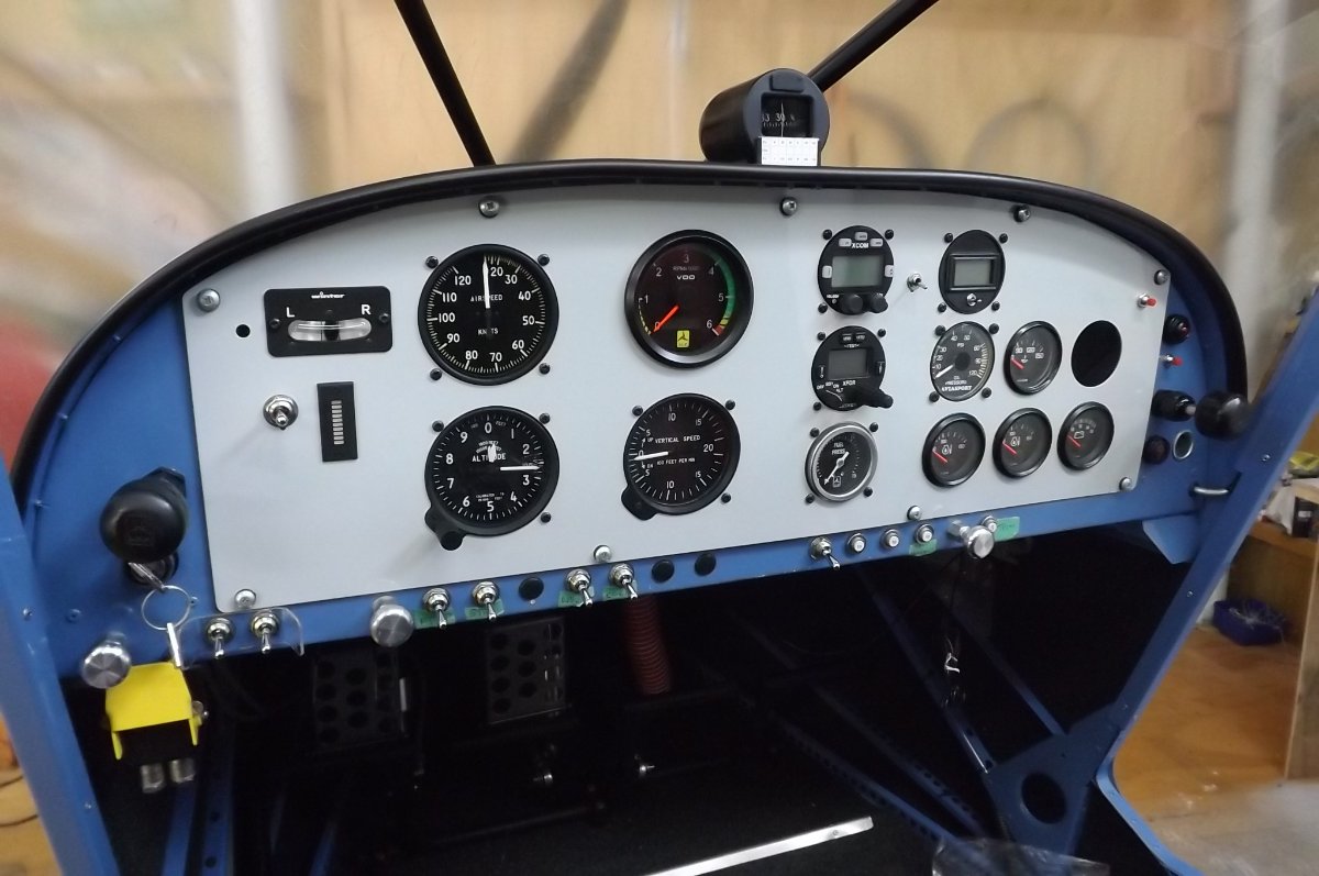
I have a separate choke that springs back: it's the silver knob at the lower left in the pic. The starter switch is just under the throttle, and it works fine for me: throttle closed, fully pull choke, hit the switch, and as soon as she fires my hand goes from switch to throttle. Pause a moment, then feed in some throttle while letting the choke off. My engine does have the timed spark retard, and that makes for much better starting than the earlier arrangement where the spark was advanced as soon as the engine hit a certain RPM. I also have a heavy negative cable from engine back to battery: some years ago i read something from an Australian Rotax guru, who reckoned he had noticed a strong correlation between aircraft with starting/sprag clutch damage problems, and aircraft that relied on the hull for the negative return. A combination of the above has always given me very good starting.
-
Tried to PM you, CScott, but you don't accept msgs?
-
Hi NathanS, and welcome to the site. Suggest you contact Mark Kyle, he posts as Kyle Communications on this site. He is the resident expert, and may well be able to help you. You can Personal Message him by going to the little envelope logo on the left (assuming you are on a computer). Select Compose New, type in Kyle as the recipient and it will bring up the Kyles. From there select Kyle Communications and drop him a message.
-
Another accident (Bristell?) near Muswellbrook 3/12/22
IBob replied to BrendAn's topic in Aircraft Incidents and Accidents
Brendan, first thanks for posting the link. For future reference, and particularly when posting about accidents and incidents, it is a good idea to post some detail and a date in the thread title. This does three things (that I can think of): 1. It means when someone adds to the thread, and it pops to the top of the "What's New' list, people can see what and when it is about. If what they see is 'Another Accident', every time the thread is added to and it pops up, it looks like yet another new accident......until you read down the thread and realise it is not. Which gets a bit tiresome. 2. It makes it very easy for folk to decide which threads to look at each time they visit the site........they can scan down the What's New, visiting or revisiting the specific items that interest them. So a specific thread title helps with this. Eg I have continuing interest in the recent US Air Show Crash.......and that thread is headed 'US Air Show Crash' with the date, so it is very easy for me to visit or revisit that thread. 3. It helps avoid multiple threads for the same event: again, if the thread title is specific, others are unlikely to start a new thread, so all the posts on that subject will tend to be on just the one thread, and so easily accessed. For me, this site has been and is a wonderful resource........while I was building, and now while I am flying. About the only drawback with the place is that there is such a huge amount being posted over the years, it can be hard to find your way around. The search function is one tool that helps there. And the other thing would be clear labelling of threads. Thanks, and blue skies. -
Maybe we should add plunging and plummeting to our Unusual Attitudes???
-
PLANE IN POWER LINES BALTIMORE 28/11/22
IBob replied to red750's topic in Aircraft Incidents and Accidents
plugga.....yep, been down that rabbit hole a while back, or one very similar, following an incident. At that time I queried FlightRadar24 as to their altitude data, which was labelled as 'calibrated altitude'. I got no sensible response as to what that was supposed to mean, but I see they have now clarified it some: "Altitude For each flight tracked on Flightradar24 the calibrated altitude reported from the aircraft, which is a pressure-derived value, is displayed. ( Extended Mode S Data received from some aircraft also includes the GPS-derived altitude of the aircraft.)" If further clarification is required, chase down the spec for ADS-B. As for the incident, if you can run down the atmospheric pressure at the time and place, it's easy to make the correction. -
PLANE IN POWER LINES BALTIMORE 28/11/22
IBob replied to red750's topic in Aircraft Incidents and Accidents
plugga I believe the ADSB data has to be corrected for barometric pressure.