Blueadventures Posted September 1, 2021 Share Posted September 1, 2021 Nice Marty, good to fit insulation boots on the ends over the terminals for added contact protection. 1 Link to comment Share on other sites More sharing options...
Marty_d Posted September 1, 2021 Author Share Posted September 1, 2021 30 minutes ago, Blueadventures said: Nice Marty, good to fit insulation boots on the ends over the terminals for added contact protection. I will when I can get some - Jaycar don't stock them. Might ask around the battery places / auto electricians. Link to comment Share on other sites More sharing options...
IBob Posted September 1, 2021 Share Posted September 1, 2021 Hi Marty, we were discussing 912 starts while working on a build yesterday: The combination of your positive and negative wiring, and the soft start (timed spark retard period) on your engine should give you prompt and faultless starts every time. It works so well, in fact, that the day I get any hesitancy or misfiring on a start will be the day I go looking for the problem. 1 Link to comment Share on other sites More sharing options...
Kyle Communications Posted September 2, 2021 Share Posted September 2, 2021 The starter motor mounting lug is the place most attach the engine earth I am doing all the avionics and engine wiring on mine now as well. I really love the hinged panel and the equipment tray I put in...so much better than hanging upside down with a headlight on trying to do the wiring 4 Link to comment Share on other sites More sharing options...
Marty_d Posted September 2, 2021 Author Share Posted September 2, 2021 Starter motor lugs it is. I like your setup Mark but I think the Sav has a bit more panel space than the 701. I don't want to lose any legroom so won't put anything below it. Today I pulled the positive cable through to the battery, measured length and cut it. Works out to 2.28m which I'm fairly happy with, I was afraid it would go over 3m. I also drilled out the rivets at the front of the pilot's seat, will need to lift and get below that to fix cable holders etc, and also to join up the isolator switch. On the negative side, (not "bad", just negative!) - I put in another gland through the firewall and ran a short section of 14mm2 from the starter motor lug through the firewall and to the back of one of the bolts holding the regulator on. Will mount the negative bus bar close to that, and also run 14mm2 from that bolt alongside the positive cable until under the pilot seat, where it'll terminate at the isolator switch. Then from other switch terminal to the negative terminal of the battery. I believe that should give a nice solid earth return - happy to take on board any suggestions though! As far as running the cables along the cabin floor under the rudder cable - have others run anything to protect them (eg a cover of some sort) or just left them exposed? Thinking a "top hat" section length of aluminium riveted to the floor may not be a bad idea. Link to comment Share on other sites More sharing options...
Kyle Communications Posted September 2, 2021 Share Posted September 2, 2021 I run the cables in a corrogated split conduit its about 30mm diameter and you can run one down each side if you like and it just sits in the bottom corner. You can keep it there by velcro if necessary 2 Link to comment Share on other sites More sharing options...
IBob Posted September 3, 2021 Share Posted September 3, 2021 1 hour ago, Kyle Communications said: I run the cables in a corrogated split conduit its about 30mm diameter and you can run one down each side if you like and it just sits in the bottom corner. You can keep it there by velcro if necessary Plus one for that. Cheap as chips from Jaycar in various diameters and does a great job of tidying it all up. Mine are cable tied at the floor below the front of the doors, and they don't shift at all. 1 Link to comment Share on other sites More sharing options...
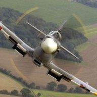
Marty_d Posted September 3, 2021 Author Share Posted September 3, 2021 *YAWN* I need sleep... Tired but happy. 5 3 Link to comment Share on other sites More sharing options...
IBob Posted September 3, 2021 Share Posted September 3, 2021 Looks great, Marty! Will there be pushbutton to test low fuel indicator, and battery discharge light? 1 1 Link to comment Share on other sites More sharing options...
gareth lacey Posted September 3, 2021 Share Posted September 3, 2021 7 hours ago, Marty_d said: *YAWN* I need sleep... Tired but happy. Link to comment Share on other sites More sharing options...
gareth lacey Posted September 4, 2021 Share Posted September 4, 2021 2 hours ago, gareth lacey said: Hi Marty Snap, your dash looking good 1 Link to comment Share on other sites More sharing options...
Marty_d Posted September 4, 2021 Author Share Posted September 4, 2021 Yours too Gareth! Three radios? Link to comment Share on other sites More sharing options...
Marty_d Posted September 4, 2021 Author Share Posted September 4, 2021 (edited) 14 hours ago, IBob said: Looks great, Marty! Will there be pushbutton to test low fuel indicator, and battery discharge light? Thanks Bob! The push button for low fuel test is on the harness so left that off for now - there's a hole for it in the middle of the main 4 gauges. Haven't got a battery light but there is a gauge for it, middle top in the right cluster. Edited September 4, 2021 by Marty_d 1 Link to comment Share on other sites More sharing options...
gareth lacey Posted September 4, 2021 Share Posted September 4, 2021 1 hour ago, Marty_d said: Yours too Gareth! Three radios? 2 radios and transponder all up cost 1200 from uk Link to comment Share on other sites More sharing options...
Marty_d Posted September 6, 2021 Author Share Posted September 6, 2021 Some more wiring today - pulled the pilots seat up and connected up the negative coming from the back of the regulator to one side of the isolator switch, and ran another cable from the other side of the isolator switch to negative terminal of battery. Also ran the positive back to the battery - through a cable gland on pilot's side seat front, then a cable clamp riveted to the floor between seat bottom and main gear, up to another cable clamp riveted to an angled tab on the seat back/bottom L angle, to the battery. The worst part was the battery end of the positive cable - because of the way it's run, had to crimp the terminal in place inside the back of the plane. My crimper is the big bolt-cutter type which when open almost reached both sides of the fuselage - had to remove the flaperon pushrods in order to get close enough! Briefly had cables hooked up to both terminals of the battery (after ensuring the isolator switch was off) in order to tie the last section of negative cable in place. Took them off again before leaving the shed! In the picture looking down inside the seat, the negative cables are actually vertically removed from the flap pushrod. 1 Link to comment Share on other sites More sharing options...
Marty_d Posted September 15, 2021 Author Share Posted September 15, 2021 (edited) Received the header tank (2nd hand) from Aerokits today. All looks good and has complete wiring to the test button - although not to light, so will have to figure that out. I think the harness that I have on already has the test button and connectors so will probably use that one. Now obviously the tank sits behind passenger and drain cock protrudes below the aircraft (and I'd always thought of it as a "her" before now!) and looks like two small bolts hold it in position. Questions for the Sav owners: 1. Is there any reinforcement below the tank or does it sit on the bottom skin? 2. Is it fairly well centred behind the passengers side? Or over to the fuse side and just enough room to clear the rudder cable? 3. How close to the main gear channel does the front of it sit? 4. On top, there's 2 large barb fittings (from the tanks) and a smaller barb which I assume is for a breather. Where does that line go? Any photos of your installs would be much appreciated! Thanks. Cheers, Marty Edited September 15, 2021 by Marty_d Link to comment Share on other sites More sharing options...
IBob Posted September 15, 2021 Share Posted September 15, 2021 Just sits on floor skin, no reinforcing, upper part is strapped to panel behind RH seat. Haven't seen one with 3 top fittings. Maybe one for each of the tanks, and the small one added later as a breather. On the Sav the breather goes into the LH inboard tank high up (and the fuel return from engine goes same place on the RH tank.) Having said that, no need for 3 fittings: normally one big one is used to bring fuel in from 1 or multiple tanks, the other big one is the breather. The low fuel switch is a simple reed switch, and when it is made (fuel low) it connects the wire to the aircraft hull. So that terminal there is normally riveted to the hull right next to the tank. The indicator at the panel has 12V on it all the time, the level switch completes the circuit by switching on the negative side. The indicator test button on the panel does the same thing: completes the circuit on the negative side. Not the best pics, sorry. 1 1 Link to comment Share on other sites More sharing options...
Marty_d Posted September 15, 2021 Author Share Posted September 15, 2021 Thanks Bob, that's excellent. Gives me the position nicely. Given the 701 doesn't have that nice rounded corner on the fuse sides, I may be able to get it even closer to the side so that port connector isn't so close to the flaperon mixer. So - if one of your big barbs is the breather, where does it run to? I'm assuming somewhere high! Link to comment Share on other sites More sharing options...
IBob Posted September 15, 2021 Share Posted September 15, 2021 (edited) On the Sav, the breather goes into a point high in the side wall of the LH (inboard) tank: it has it's own fitting there. (I guess it could also be teed into the upper sight glass fitting, provided that tube was level or uphill from the tee to the tank, that would be one less fitting in the tank.) On the pics the RH top tube is the fuel coming in, the LH top tube is the breather. The breather pipe does a very tight bend under the mixer, that steel pipe is excellent as it holds the bend you put in it, and bends without collapsing. You can also see the low fuel switch wiring lug riveted to the crossmember in the bottom pic. And the cable run in the black corrugated stuff at the base of the tank in the second pic down is the main battery + and - cables and the lead from the low fuel switch going forward. The other visible wiring is from the Magnum box to the wingtip strobes. Edited September 15, 2021 by IBob 1 Link to comment Share on other sites More sharing options...
IBob Posted September 15, 2021 Share Posted September 15, 2021 On the Sav, the breather goes into a point high in the side wall of the LH (inboard) tank: it has it's own fitting there. (I guess it could also be teed into the upper sight glass fitting, provided that tube was level or uphill from the tee to the tank, that would be one less fitting in the tank.) On the pics the RH top tube is the fuel coming in, the LH top tube is the breather. The breather pipe does a a very tight bend under the mixer, that steel pipe is excellent as it holds the bend you put in it, and bends without collapsing. You can also see the low fuel switch wiring lug riveted to the crossmember in the bottom pic. And the cable run in the black corrugated stuff at the base of the tank in the second pic down is the main battery + and - cables and the lead from the low fuel switch going forward. The other visible wiring is from the Magnum box to the wingtip strobes. Link to comment Share on other sites More sharing options...
Marty_d Posted October 31, 2021 Author Share Posted October 31, 2021 Fuel... again... firstly I did what I should have done ages ago and checked the plans. 1/4" fuel line is perfectly fine for the 701. So that's a relief, and probably why I bought those 1/4" quick release fittings from Aircraft Spruce in the first place. So - I made up a small L-shaped piece today from 0.032" to take the two quick release fittings in the L/H wing root, put a 3/8" to 1/4" reducer in the line from the tank and hooked them up. I will put a small inspection port under so that by removing a couple of screws I can disconnect the fuel lines just by pushing the release buttons from underneath. The good thing is that these close off both hoses when released, so in theory there shouldn't be any fuel leakage even when there's fuel in the tank and the header (and the lines going to it) are full. On the L/H tank the line going forward to a fitting at the top of the tank is for a breather from the header tank, and also will have the fuel return from the engine T'd into it. 2 Link to comment Share on other sites More sharing options...
planedriver Posted October 31, 2021 Share Posted October 31, 2021 Looks good Marty! Loving watching you progress in your build. Don't forget to some sleep too. Rgds Planey 1 Link to comment Share on other sites More sharing options...
Marty_d Posted December 19, 2021 Author Share Posted December 19, 2021 Time for a quick update - I've been doing more work on the fuel system, received my EFI-type hose clamps and also Peter (@nomadpete) very kindly gave me a couple of fuel taps that had previously graced his Lightwing. So I've got those mounted on a piece of aluminium that will be riveted to the fuselage side, with hard line going down through the baggage floor then bending to the top of the header tank. From the bottom of the header tank is firstly a filter, then hard line goes under the flaperon torque tube to the Facet electric fuel pump (which was also donated from a forum member - thanks Rob!!) - and then a long run of hard line under the pilot's seat, through the cabin and through the firewall. I've also been considering a prop and very tempted by the E-Props that Mark Kyle is the Australian rep for. They come with a spinner, smallest is 210mm diameter. I'm modifying the cowl to put a 210mm ring on the front which ends 5mm behind the front face of the drive plate. I bought some high-density foam from Bunnings today, made up a 210mm circle of MDF which bolts onto the drive plate and has a ring of 5mm ply behind it. I've put in a ring of the foam, some more tidying up to do later. The foam is very light, so I think I'll leave it in place, sand to a nice finish and fibreglass (carbon fibre) straight over it. Once I have the foam glued into place I'll take the wooden holder off before fibreglassing. 8 Link to comment Share on other sites More sharing options...
Marty_d Posted December 21, 2021 Author Share Posted December 21, 2021 A couple I forgot to attach on Sunday - header tank to filter, and then the electric fuel pump onwards. 4 Link to comment Share on other sites More sharing options...
Marty_d Posted January 2, 2022 Author Share Posted January 2, 2022 Finally some fibreglassing weather - the week from Christmas to New Year was excellent down here (today it started raining again!) I made a mockup of the firewall, screwed the cowl to it in the spots it's going to be connected, and moved the whole thing up to the carport. Resin stinks! Unfortunately the other thing polyester resin does is cause foam to deform. I had started slathering the outside of the ring with a mix of poly and microballoons, but it shrunk the outer surface of the foam (see first pic). So I did what I should have done in the first place, and coated the foam ring with epoxy. After that went off I spent about 4 days doing coats of microballoon, sanding, repeat. Fairly happy with the end result - I've run out of micro balloons so will have to get some more to fill a couple of very small divots, then I can cut the top cowl away again, cover the ring with carbon fibre and do some final filling. I've been sharing my carport with another family - a couple of swallows and their 4 chicks. The nest is getting a little crowded now. Poor mum & dad spend all day on the wing, ferrying back food for the kids - at first they would buzz me if I was in the carport but now they just ignore me. 4 Link to comment Share on other sites More sharing options...
Recommended Posts
Create an account or sign in to comment
You need to be a member in order to leave a comment
Create an account
Sign up for a new account in our community. It's easy!
Register a new accountSign in
Already have an account? Sign in here.
Sign In Now