
Admin
-
Posts
9,304 -
Joined
-
Last visited
-
Days Won
109
Content Type
Profiles
Forums
Gallery
Downloads
Blogs
Events
Store
Aircraft
Resources
Tutorials
Articles
Classifieds
Movies
Books
Community Map
Quizzes
Videos Directory
Everything posted by Admin
-
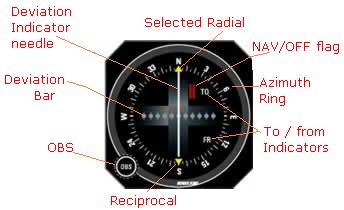 4.9.1 Non-directional beacon In Australia the non-directional beacons [NDBs] are the oldest established and, though technically obsolescent, still the most common radio navigation aid. The beacons are usually located at or near an airfield (they were originally called homing beacons), although a very few are still sited to mark waypoints along air routes. The reason they are called 'non-directional' is that the aural radio ranges they originally replaced had directional antennas. The NDBs transmit an omni-directional carrier signal in the low frequency band between 190 and 535 kHz. Their effective range is primarily dependent on the operating power. Most inland NDBs have a transmitter power between 100 and 500 watts providing a range, during daylight hours, usually between 40–100 nm but tending toward the lesser figure. The rated coverage of each NDB is shown in the ERSA entry for the airfield or waypoint. Low-power NDBs, known as 'locators' with a range of 30 nm or less, are sited around major airports and are associated with their instrument landing systems [ILS]. There are also high-power (2–3 kW) NDBs sited near the coast to provide guidance for overwater routes, their over water range being much greater than their inland range. Identification The carrier wave is transmitted on a specific frequency, but a two- or three-letter Morse code signal is continually superimposed on the carrier for NDB identification. The frequency and identification for each beacon is given in ERSA and shown on VNCs, ERC-Ls and VTCs. Some NDBs may provide an intermittent 'voice-over' facility for airfield information. If you want to practise, the morse code dots and dashes are rendered phonetically as 'dits' and 'dahs'. If a Bureau of Meteorology automatic weather station [AWS] is located at an aerodrome that also has an NDB then an aerodrome weather information service [AWIS] may be available at that station. The NDB installation includes voice modulation on the carrier to broadcast the actual, or recent, weather conditions. For further information consult AIP GEN 3.5 para 7.4. AM broadcast stations The companion airborne system which makes use of the NDBs — known as automatic direction finding [ADF] equipment — can also receive transmissions in the 520 to 1611 kHz AM broadcast band. The power output of the broadcast stations is usually considerably greater than NDBs — typically 2, 5, 10 or 50 kilowatts — so their signal can be received at a greater distance. The transmission frequency, power and latitude/longitude of broadcast station transmitters are shown in the NAV/COMM section of ERSA. Broadcast stations must be used with caution because of identification problems. There are long intervals between station identification calls and even then the transmitter to which you are tuned may be relaying programs from another station. The information contained in ERSA may not be up to date. 4.9.2 ADF equipment The ADF, or radio compass, equipment consists of an antenna system, a receiver/control box system and a panel-mounted indicator instrument. The antenna system comprises a loop antenna and a sense antenna which, depending on the age of any particular unit, may be completely separate or combined into one unit. The ADF receiver includes the frequency selector (probably 190 to 1799 kHz) and usually some test capability. The loop antenna nowadays may be a fixed square ferrite core with two perpendicular windings and may be coupled with a goniometer — (a device for measuring angles, with a great number of scientific applications) — in the receiver. Such a system automatically ascertains the direction of the transmitter relative to the longitudinal axis of the aircraft. Hence the reason for the term "Automatic" DF because in earlier days the loop antenna was a physical loop (mounted on top of, or beneath, the fuselage and often enclosed in an egg-shaped fairing) which, simply put, had to be manually rotated by the operator to find the direction of the transmitter, which was read off a scale. At that time, and later, the sense antenna was a wire from the top of the tail fin to a fuselage connection. The output from the receiver is fed to the panel-mounted instrument, which is a needle indicating the direction to the NDB, or broadcast station, as an angle relative to the aircraft's longitudinal axis. Behind the needle is a circular card marked off in 5-degree azimuth divisions from 0° to 355°, with a mark at the top dead centre [TDC] indicating the aircraft's nose. Depending on the age of the instrument, that card may be fixed — in which case 0° is always at TDC — or, more commonly, manually rotatable by turning a heading knob on the instrument. If the card is rotated so that the aircraft's current magnetic heading is situated at TDC then the head of the needle indicates the magnetic track to the transmitter and the tail of the needle indicates the reciprocal bearing — the aircraft's magnetic bearing from the station. When using the ADF indicator it should be normal practice to adjust the card whenever the aircraft's heading is changed. The illustration shows the ADF instrument with the heading knob [HDG] rotated so that the aircraft's heading of 350° magnetic is at TDC; the needle head indicates the track to the NDB is 155° magnetic while the bearing from the transmitter is 335°. However, whether the card is fixed or rotatable, the head of the needle should always point directly to the transmitter and the angle (the number of degrees) between TDC and the head of the needle is always the angle between the fore and aft axis, and the direction of the transmitter. In the illustration that angle is 10 + 155 = 165°. Heavier aircraft are usually fitted with a more complex and very expensive form of ADF called a Radio Magnetic Indicator [RMI], which incorporates, or is slaved to, a directional gyro. It may also have a two-needle display, the second needle being tuned to another navigation aid which, of course, makes position fixing remarkably easy. 4.9.3 ADF applications There are several applications for the ADF in light aircraft cross-country VMC navigation — remembering the Visual Flight Rules require that the pilot must be able to navigate by reference to the ground, and position fixes must be taken at least every 30 minutes. The applications briefly described below will be detailed in the 'Using the ADF' module. Position fixes. If two (three is best) transmitters are in range then the bearing from each can be ascertained, the lines of position roughly plotted on the chart (after converting to true bearings) and the aircraft position will be close to the intersection point. In most of Australia, to have two NDBs in range at the same time is not so common and three would be most unlikely, so the most likely position-fixing use is to combine a surface line feature with an NDB bearing. Running fix / distance from NDB. The 1-in-60 rule can be applied when the aircraft is within range of a transmitter by turning the aircraft so that the station is abeam and then measuring the degrees traversed against time. This is a form of running fix in that two bearings are taken, at an interval, from one source and the aircraft's position is the distance along the second LOP from the NDB. For example: Distance (nm) to NDB = elapsed time (mins) × ground speed (kn) / degrees traversed Homing and tracking to or from an NDB. If there is no crosswind component then tracking toward an NDB is quite simple — just keep the head of the ADF needle at TDC and you will arrive overhead; the track over the ground will be straight and the magnetic heading constant. However, if there is a crosswind component and you just endeavour to keep the head of the ADF needle at TDC, you will eventually arrive but, due to the drift, the track followed will be curved and the magnetic heading will need to be consistently changing. This is called homing, and you will arrive at the NDB on an into-wind heading. Thus tracking, or flying directly towards, or from, an NDB is exactly the same as tracking from A to B — you have to calculate a wind correction angle. Passing overhead an NDB is signified by a "cone of silence" (if the 'ident' volume has been turned up beforehand) and the needle then swings to the reciprocal bearing. Using the ADF probably appears to be fairly simple, which it is, but there will be difficulties — for the uninitiated in perceiving, from the position of the needle, the headings to fly when attempting to intercept and then track along a particular magnetic bearing to or from the ground station. As in all navigation you should always maintain an awareness of the aircraft's position in terms of being north, south, east or west of the NDB and, when initiating a turn, think in the same terms; e.g. a left turn will take you further east. 4.9.4 NDB/ADF errors Electrical interference. Radio waves are emitted by the aircraft alternator in the frequency band of the ADF. An alternator suppressor is fitted to contain those emissions but this component does not have a long life and it is wise to test the ADF for correct operation during pre-flight checks. The test is made by selecting a transmitter — which must be a reasonable distance away, say 30 nm – then watch the ADF needle during the engine run-up. If the needle moves as rpm increases there is electrical interference and probably the alternator suppressor should be replaced. Magnetos may also interfere with the ADF. Thunderstorms emit electrical energy in the NDB band and will deflect the ADF needle towards the storm. Twilight/night effect. Radio waves arriving at a receiver come directly from the transmitter — the ground wave — and indirectly as a wave reflected from the ionosphere — the sky wave. The sky wave is affected by the daily changes in the ionosphere; read the ionisation layers section in the Aviation Meteorology Guide. Twilight effect is minimal on transmissions at frequencies below 350 kHz. Terrain and coastal effects. In mountainous areas NDB signals may be reflected by the terrain, which can cause the bearing indications to fluctuate. Some NDBs located in conditions where mountain effect is troublesome transmit at the higher frequency of 1655 kHz. Ground waves are refracted when passing across coast lines at low angles and this will affect the indicated bearing for an aircraft tracking to seaward and following the shore line. Attitude effects. The indicated bearing will not be accurate while the aircraft is banked. 4.9.5 VHF Omni Range In Australia the VHF omni-directional radio ranges [VORs] operate in the Very High Frequency aviation navigation [NAV] band between 112.1 and 117.9 MHz. As VHF transmissions are line-of-sight, the ground-to-air range depends on the elevation of the beacon site, the height of the aircraft and the power output. The VOR beacons are usually located at airfields but as they serve to define designated air routes (airways) some are located away from airfields, often on high ground. A simplified concept of the ground beacon is that it simultaneously transmits two signals, a constant omni-directional signal called the reference phase and a directional signal which rotates through 360°, during a 0.03 second system cycle, and consistently varies in phase through each rotation. The two signals are only exactly in phase once during each rotation — when the directional signal is aligned to magnetic north. Imagine a wheel with 360 spokes, at one degree azimuth spacing, with the VOR beacon being the hub. The spokes are numbered clockwise from one to 360 and each spoke or radial represents a magnetic bearing from the VOR beacon. The airborne navigation circuitry measures the phase angle difference between the directional signal phase received and the reference signal phase, and interprets that as the angular, or 'radial', indication currently being received. Radials are identified by magnetic bearing — e.g. the 30° radial — and thus form the basis for VOR and designated air route navigation. Essentially the system indicates a line of position from the selected VOR, on which the aircraft is located at any time. The beacon also transmits a Morse code aural identification signal at about 10 second intervals. The airborne system utilising the VOR beacon transmissions usually consists of an antenna (probably a V-type dipole mounted horizontally on the fin or fuselage, but could be the more expensive 'blade' or 'towel rail' types), a conventional VHF receiver (if combined with the VHF communications transceiver it is then called a NAV/COMM unit), navigation circuitry and the separate panel-mounted navigation indicator or 'omni bearing indicator' [OBI]. Some hand-held aviation COMMS transceivers can also receive the NAV band VOR transmissions and appear to have some navigation circuitry but, from all reports, their VOR navigation capability, if it exists at all, is limited. A basic OBI , like the above Bendix-King model, has a manually operated radial or 'omni bearing' selector [OBS] that rotates an azimuth ring marked from 0° to 355°. The OBS selected radial is indicated by the arrow at top dead centre and the reciprocal bearing is indicated by the bottom arrow. The other features of a basic OBI are the TO–FROM indicators, a deviation bar, a deviation indicator needle and a NAV/OFF alarm flag. The TO–FROM logic The TO–FROM indications on the OBI are dependent on the aircraft's position relative to a notional ground baseline, formed perpendicular to the selected radial and passing through the beacon site. Unlike the NDB the indication is completely independent of the aircraft's heading. The navigation circuitry compares the difference between the radial being received and the radial selected. If the aircraft is located anywhere within range on the radial side of the baseline, the 'FROM' indication will be displayed on the OBI and, if located within range on the reciprocal side, the 'TO' indication will be displayed. For example if the 030° radial is selected on the OBI, the ground baseline is established between 300° and 120°. If the radial received indicates the aircraft is anywhere in the blue shaded area of the diagram and no matter whether it is headed towards or away from the VOR, or in any direction whatsoever, the OBI will display 'FROM'. Similarly if it is in the yellow area the OBI will display 'TO' no matter which direction the aircraft is headed. There are two areas of ambiguity – near bearings at right angles to the radial (e.g. shown at 120° and 300°) – where the OBI will give fluctuating indications, or display the 'OFF' flag. The course deviation indicator The deviation bar and the deviation indicator needle together form the course deviation indicator [CDI]. If the needle is over the centre point the aircraft is then located at some position along the selected radial — or its reciprocal. The five division marks or dots either side of the centre point are spaced at two-degree intervals, thus if the needle is over the third mark, left or right of centre, the aircraft is positioned at a radial six degrees in azimuth from the selected radial, or its reciprocal. (Actually the aircraft is at the centre mark and the needle indicates the position of the selected radial). Full travel of the needle from the centre to either side represents 10° or more of azimuth. The ambiguity of whether the OBS selection is the radial or the reciprocal is determined by the TO/FROM indication; in the diagram at left 030 must be the radial, as the aircraft is in the FROM area. When the aircraft passes overhead the beacon, the needle will swing from side to side, the alarm flag may temporarily indicate that navigation is 'OFF' and the TO/FROM indication will reverse. A difficulty for a non-IFR trained pilot using the VOR is a lack of perception of which way to turn the aircraft to fly to a selected radial, using the CDI indications. However, for VFR purposes, this is easily ascertained if the pilot follows two simple rules: 1. To track FROM a VOR select the radial required and ensure FROM is indicated. 2. To track TO a VOR rotate the OBS until the CDI is centred and TO is indicated. In both cases as wind effect drifts the aircraft off track the deviation indicator needle will move to one side and that movement indicates the direction to turn to regain track. i.e. turn towards the needle. 4.9.6 VOR applications Like the NDB/ADF there are several applications for the VOR in light aircraft cross-country VMC navigation. The applications are briefly described below. Homing and tracking to a VOR. Even with a crosswind component, tracking toward a VOR is quite simple — rotate the OBS until the CDI is centred and TO is indicated, turn onto that magnetic heading and then just keep the CDI centred and you will track more or less directly to the VOR. Tracking from a VOR. Rotate the OBS to the required track (radial), ensure FROM is indicated, turn onto that magnetic heading and just keep the CDI centred and you will maintain the track. Position fixes. If two VORs are in range then the bearing from each can be ascertained, roughly plotted on the chart (after converting to true bearings) and the aircraft position will be close to the intersection point of the LOPs. Alternatively a VOR bearing and a NDB bearing can be used, or a VOR bearing and a line feature on the chart — the latter technique being the most frequently used. Running fix/distance from VOR. The 1-in-60 rule can be applied when the aircraft is within range of a transmitter by turning the aircraft so that the station is abeam and then measuring the degrees traversed against time, as in the NDB running fix application above. The advantage with the VOR is that the CDI needle indicates the degrees traversed. As in the NDB application, the position fix is the distance along the second radial from the beacon. VOR simulator If your browser is Java enabled then I suggest a visit to www.fergworld/training/ and try out the single VOR trainer applet. Drag the aircraft symbol to position your aircraft, set the aircraft's heading on the directional gyro, rotate the OBS to a desired radial and check the CDI and flag. Then try to intercept the radial and track to or from the VOR, by changing heading and dragging the symbol along the flight path.Try the quiz. 4.9.7 VOR errors Standard VOR systems are more accurate than NDB/ADF but are still subject to errors at the ground station, bending distortion of signals caused by terrain effect and avionics errors. The aggregation of all errors is very unlikely to exceed 5°. Though very thin on the ground in the outback areas of Australia, NDB and VOR can be very useful, provided the aircraft is within range, but not the best value for money. That distinction now belongs to another, and more advanced, supplementary navigation tool — the Global Positioning System. STRICT COPYRIGHT JOHN BRANDON AND RECREATIONAL FLYING (.com)
 -
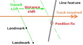 4.8.1 Setting compass heading Before we reach the set-course point of our flight we have to determine the compass deviation known to occur at that magnetic heading — if the deviation has been measured and if there is a compass correction card displayed in the aircraft. Such a card might look like this, although it is more likely to be expressed in 30° rather than the 45° intervals shown: Compass correction card Heading magnetic 045° 090° 135° 180° 225° 270° 315° 360° Compass correction +2° +5° +2° 0 -2° -5° -2° 0 To find the heading to set on the compass just add the deviation value to, or subtract it from the magnetic heading. For example, our heading on the flight from Oxford to Warraway Mountain is 079° magnetic. Interpolating between the values shown for 045° and 090°, the correction for 079° is +4°. Thus the compass heading to steer is 083°, the magnetic heading will then be 079° and the true heading will be 090°. 4.8.2 Monitoring and recording flight progress Position fixing methods Monitoring involves checking from clock to map to ground — anticipating what should be in view a few minutes ahead — plus intermittent position fixing to establish the track made good, and estimating the track error and the actual ground speed. The essential navigation instruments are just the compass and the clock — to provide direction and ground speed. Deviations from the track required occur because: the pilot is not maintaining the planned heading or has set the wrong heading; e.g. the heading for a different leg. unrecognised compass error (deviation) causes the heading flown not to be the planned magnetic heading. There should be no extraneous ferrous materials (e.g. the rings on a binder) near the compass, or larger items anywhere in the cockpit. the wind velocity is substantially different from that used for the flight plan or it was applied incorrectly during flight planning the required track direction was incorrectly measured — or converted to magnetic — during flight plan preparation. In eastern Australia, where magnetic variation reaches 13°, reversed application of variation when calculating the magnetic heading can result in a very large heading error. There are basically two methods of fixing the aircraft's position. The first and the most common in light aircraft navigation is by identifying a landmark close to the aircraft. The second is by identifying (or establishing) two or more lines of position [LOP] such that their point of intersection provides the position fix. A line of position is a line drawn, or an existing line feature, on the chart indicating that the aircraft's position is somewhere along it. Note that there should be a reasonable angular difference, maybe more than 30°, between two LOPs in order to derive a useful position fix. A LOP might be: a clearly identifiable physical identity such as a long road, railway or river that the aircraft is about to fly across — but without any supporting indication of exactly where the crossing is being made a visual bearing from an identifiable landmark. Or an instrument bearing from a radio beacon, which we will discuss in the 'Supplementary navigation techniques' module a transit. When two identifiable landmarks are seen to be in line with each other the aircraft must be somewhere on the extended sight line. It is a good practice to identify suitable landmark pairs in the flight planning stage, and mark on the chart the transit line between them, extending it across the track required — thus pre-marking the LOP. It is not always possible to derive two LOPs, more or less simultaneously, to get a position fix at their intersection. However, if a second LOP can be derived within, say, 10 or 15 minutes of the first then a running fix can be ascertained. This is done by estimating the distance flown along the track during the lapsed time and then shifting the initial LOP that distance. The intersection of the shifted line and the second LOP is the position fix. (There is another form of running fix involving two bearings from the same object but this is really a technique applicable to radio navigation aids and we will look at it in the 'Supplementary navigation techniques' module.) Recording progress An accurate running log of LOPs or position fixes, segment start and finish times, magnetic headings, and fuel consumption must be maintained — it is very difficult to remember times and headings flown — and the log need only be a blank note pad. For example the first note made is the engine start-up time and the second is the set heading time. The minutes elapsed between those times is then noted on the fuel log 'Airfield departure' line in the 'Actual' column. All events logged should be preceded by the time and all the magnetic headings flown must be logged, even when that heading is the planned heading. As each route segment is commenced, log the ETA for the next waypoint or major landmark, which will be the current time plus the flight plan ETI (or an adjusted ETI) for that segment. As each route segment is completed, the elapsed time is transferred to the fuel log. 4.8.3 Track error adjustments The track plot below shows the first leg of our planned flight between Oxford and Tottenham. The green lines are the 10° drift lines and the pink marks along the track are the 10 nm distance marks. In this example the first three marks are distance from Oxford, the last three are distance from Warraway Mountain, and the longer mark is the track midpoint. Instead of distance marks some navigators favour time marks at, say, 10-minute intervals. However time marks really don't correlate that well with charts — time notations should be shown in the log. As it is remarkably easy to set off in the wrong direction — reversed application of variation for instance — it is advisable to note a landmark as a means of verifying that, at the set-course point, you really are setting off along the required track. The sun's position provides a gross indication of heading, which will at least confirm that you are not flying the reciprocal course. Starting off in the wrong direction, without realisation, really makes progress monitoring difficult when you are flying over relatively featureless terrain. In addition, a position fix must be acquired within 15 to 20 minutes of the set heading time. At any time after departure, when the aircraft's position has been pinpointed and found to be off track, heading adjustments will be necessary. Initially this is to regain the required track and then to maintain it; or, alternatively, for a new heading to track directly to the next turning point. There are several methods for calculating and applying heading adjustments — a pencil and paper will be handy. Double track error method This is the recommended method if the position fix shows the aircraft to be less than halfway along the leg — hence the reason for marking that midpoint on the chart. The procedure is as follows: 1. Using the diverging 10° drift lines estimate the track error — the difference in degrees between the track required and the track made good. The track error is also referred to as the opening angle or sometimes as the drift angle. (The term 'drift angle' in this context is deprecated, as it normally refers to the angular difference between the heading flown and the track made good.) For example let's say, on our Oxford to Warraway Mountain segment, we find ourselves crossing the railway line at Trida and estimate the track error as 6° north of required track; i.e. the track made good is 077° magnetic. We log the time and note 24 minutes have lapsed since departing the set-course point. 2. Double the track error and add or subtract that value from the planned heading to arrive at the heading to regain track or the intercept. If the drift was to the right of track the new heading must be to the left of the original heading and, conversely, if drift was to the left the new heading must be to the right of the original. The time we must remain on this new heading, until intercepting the required track, is roughly equivalent to the time flown on the original heading. Although we have used the terms 'left' and 'right' you will find it more helpful, when considering position, to think in terms of 'north', 'south', south-west' etc. For example track error is 6° north (left) and original heading 079° magnetic, thus the heading to regain track is 079 plus 12 = 091° magnetic (096° compass) and we fly that for 24 minutes — the same time as that flown on the original heading. 3. After it is visually evident that the required track has been reached, or the required time has passed, subtract the track error and turn onto the new heading to maintain the required track and log the event. For example the track error was 6° and the heading to regain track is 091° magnetic, thus the heading to maintain track is 091 minus 6 = 085° magnetic (090° compass) and we fly that until either a new position fix is obtained or we reach the waypoint. Theoretically this method doesn't work if the position fix is past the halfway point, because the point at which the required track is finally regained would be past the waypoint. Track error/closing angle method The recommended method if the position fix shows the aircraft to be more than halfway along the leg, or if you choose to fly directly to the waypoint at any time, is as follows: 1. Using the diverging 10° drift lines estimate the track error or opening angle — the difference in degrees between the track required and the track made good. Then using the converging drift lines estimate the direct track to the waypoint, and the angle between that track (the new required track) and the original required track. This is usually called the closing angle. For example, let's say on our Oxford to Warraway Mountain segment we fix our position as one mile south of the Dundooboo Ridge with an estimated track error of 7° north of required track and the closing angle to the waypoint is about 9°. 2. Add the track error and closing angle, and apply the value as a correction to the original heading. If the drift was to the left of the required track the new heading will be to the right and vice versa. For example, 7 plus 9 is 16°, drift was to the left of the original heading 079° magnetic, thus the heading — to track directly to the waypoint — is 095° magnetic (100° compass). Flight direct to landmark A third method might be employed if after getting a position fix a landmark known to be on, or close to, the required track is positively identified. • Having pinpointed your position use the diverging 10° drift lines to estimate the track error, then fly directly to the identified on-track landmark. To maintain the required track it will be necessary to turn onto a new heading when overhead the landmark. The new heading will of course be the original heading plus/minus the track error. Utilising the 1-in-60 rule The 1-in-60 rule of thumb can be used to determine track error, given distance travelled and distance off track. It replaces the use of drift lines but the latter is much the easier method to use in flight because the angle is easier to estimate than the on-chart distance off track, and the mental arithmetic is easier. However, just to keep you informed, here is the 1-in-60 method for track error calculation. 1. Having pinpointed the aircraft's position, estimate the distance off track and the distance travelled along the leg. The track error = the distance off track [DO] divided by the distance travelled [DT] × 60; i.e. the track error = DO/DT × 60. Or conversely the distance off track [DO] = track error/60 × DT For example, let's revert to our Oxford to Warraway Mountain segment where, after 24 minutes flight, we pinpoint our position at Trida. Trida is about 3 nm north of required track and 22 nm distant from the departure point. Thus 3/22 × 60 = 8° track error. The track error we estimated using the drift lines was 6°, but that's basic navigation for you. 2. To regain the required track double the track error and when the required track is reached, or the time has elapsed, subtract half the error and take up the new heading. In this aspect it's the same technique as the double track error method. 3. Or to track direct to the next waypoint calculate the closing angle — which will equal the distance off track [DO] divided by the distance to go [DTG] × 60; i.e. closing angle = DO/DTG × 60. For example, Trida is 52 nm distant from Warraway Mountain. Thus 3/52 × 60 = 3° closing angle. The new heading is the original heading plus track error plus closing angle = 079 + 8 +3 = 090° magnetic — as in the track error/closing angle method. Each time the aircraft's position is pinpointed and the heading is adjusted, a re-calculation of the ground speed and ETI for the segment should be made on the running log. The 1-in-60 rule has use in this aspect of navigation, see 'Re-assessing wind velocity'. Diversions — 30° and 60° dog-legs There is another navigational adjustment technique occasionally mentioned as a standard method of diversion around hazards or no-fly areas such as towns. As no such diversions would be necessary if the flight plan is properly prepared, such techniques should be of practical use only when something of interest is spotted off track and you divert for a little sight-seeing. The method is as follows: • When you judge the point of interest is about 30° off your current heading, alter course 30° towards the target. Note the time when the target is reached and then turn 60° in the reverse direction and fly that heading for the same time as the first part of the dog-leg, then revert to the original heading. The time lost during the two legs (which has to be added to the ETI for the segment) is one third of the time flown on the first (or either) leg and, of course, you have to add to the ETI any time spent circling over the target. • The 60°dog-leg is much the same except that you alter course when the target is 60° off the original heading, the alteration to return is 120° and the time lost flying the dog-leg is the time spent on the first (or either) leg. For example, if we were about halfway along our track from Oxford to Warraway Mountain, we thought it a good idea to have a look around the Warranary Hill. Thus we turn 60° left from our original heading of 079° magnetic to 019° magnetic, fly that for, say, six minutes then turn right 120° to 139° magnetic and fly that heading for six minutes. Then turn left 60° back on to our original heading of 079° and add six minutes to our ETI and/or ETA. 4.8.4 Recalculating ETI/ETA and fuel consumption Checking ground speed Being off-track, because of a variation in wind, is much more likely to be noticed quickly than if on track but adversely affected by a stronger than expected headwind, or tailwind. Whenever a position fix is obtained, whether it is on-track or off-track, it is advisable to calculate the ground speed achieved and to re-estimate the ETI for the leg, ETA at the next waypoint and at the destination. Ground speed [GS] in knots is distance travelled [DT] / elapsed time in minutes [ET] × 60; i.e. GS = DT/ET × 60. For example, reverting to our Oxford to Warraway Mountain segment where, after 24 minutes flight, we pinpoint our position at Trida, 22 nm distant from the departure point and about 52 nm from the next turning point. Ground speed = DT/ET × 60 = 22/24 × 60 = 55 knots. Recalculating ETI Time in minutes to the next checkpoint, turning point or destination = distance to go [DTG] / GS × 60; i.e. time = DTG/GS × 60. e.g. Time to the next turning point = DTG/GS × 60 = 52/55 × 60 = 57 minutes. There is a slightly simpler means to estimate the time to the next turning point. A ground speed of 60 knots is one nm per minute so at 60 knots the distance of 52 nm will be covered in 52 minutes. However, our ground speed of 55 knots is about 10% less so the time will be 10% greater than 52 = 57 minutes. Our ground speed at 55 knots is nearly 20% less than the flight plan figure of 67 knots and our ETI for the first leg is now 57 + 24 = 81 minutes; some 15 minutes — or more than 20% — greater than the flight plan figure of 66 minutes. This decreased performance is most likely caused by an easterly wind speed much greater than the forecast. The summed flight plan en route time was 144 minutes and 20% of this is about 30 minutes — which makes a significant inroad into our 40-minute above-reserve fuel margin. We will have to closely monitor progress, as we are getting near to the point of considering diversion to an alternate airfield. Re-assessing wind velocity The headwind component of the wind speed must be our true airspeed (75 knots) minus our ground speed (55 knots); i.e. 20 knots. However, the crosswind component is difficult to estimate because we don't know what caused the drift away from the track required. It could be unadjusted compass deviation, poor heading holding or changed wind velocity — or a combination of all three. However, let's assume we found ourselves over Trida only because the wind varied substantially from that assumed in the flight plan. If so, what is the crosswind component? To measure the crosswind component we need to measure the drift angle — the angular difference between the heading flown and the track made good [TMG]. For example, at Trida TMG was estimated as 6° left of the track required (083° magnetic) thus 077° magnetic and the heading flown was 079° magnetic. The drift angle is then 2° left, rather than the expected 4° right. Using the 1-in-60 rule, the crosswind component in knots = the drift angle/60 × TAS in knots. For our Trida position fix, the crosswind component is thus 2/60 × 75 = 2.5 knots. We can now estimate the wind direction by first ascertaining the ratio of crosswind to headwind, which in this case is 2.5/20, and then, using the 1-in-60 rule, calculate the wind angle relative to the aircraft's heading. The equation is: wind angle = crosswind/headwind × 60 = 2.5/20 × 60 = 7°. As the drift recorded was to the left, the wind must be coming from 7° to the right of heading, the heading being flown was 079° magnetic thus the wind direction is 086° magnetic or 097° true and its speed must be very close to 20 knots. Summary of track angle definitions Track error — the angular difference between the track required and the track made good. You may come across the term cross track error [XTE] which refers to the distance off track. Opening angle — another term for angular track error. Drift angle — the angular difference between the heading flown and the track made good. Closing angle — the angular difference between the direct track to the waypoint and the original required track, measured at the waypoint. Wind angle — the angular difference between the heading flown and the estimated wind direction; i.e. the wind relative to the aircraft rather than the ground. Checking fuel consumption Fuel flow indications are monitored for abnormalities as part of the continuing in-flight instrument scan. A calculation of consumption rate should be made at half-hourly or hourly intervals to check for any significant variation from the hourly consumption rate used in the flight plan. Fuel consumption should always be measured in terms of time not distance. 4.8.5 Diverting to an alternate airfield During flight the pilot should always be aware of the general direction of the planned alternate airfields so that, should a diversion be deemed necessary, the aircraft can then — after verifying current position — be headed in the general direction of the selected alternate without unnecessary delay. The mental calculations required to refine the heading, estimate distance, ETA and fuel requirement are then done without wasting time and fuel. For example, let's say that we reach our turning point at Warraway Mountain 85 minutes after the set heading point; i.e. the actual time interval [ATI] is 19 minutes, or nearly 30%, greater than our ETI of 66 minutes. Under these circumstances we could expect that the total en route time would also increase by 25% to 30%, even though the next two legs are swinging out of wind by 30° or more. This adds around 40 minutes to total time and reduces the planned fuel margin above reserve to zero so a diversion to Condobolin is warranted. The bearing is about due east so we would note the time and alter heading slightly to 079° magnetic. Looking at the chart the distance from Warraway Mountain to Condobolin is easily estimated (knowing that the distance between the meridians on the grid of this WAC is 25 nm) at about 55 nm and the bearing is not quite due east, say 088° true. Our ground speed will not alter from that established between Oxford and Warraway Mountain where we covered the distance of 74 nm in 85 minutes — 74/85 × 60 = 52 knots. The ETI from Warraway Mountain to Condobolin will be 55/52 × 60 = 63 minutes and our fuel log will look something like this: Fuel calculation and fuel log Cruise fuel flow: 16 litres/hr Usable fuel loaded: 64 litres Endurance: 240 mins Estimate Actual Airfield departure: 10 mins 12 Climb penalty: 6 mins 6 En route: Oxford – Warraway: 66 mins 85 Warraway – junction Cond'n: 48 63 mins Junction – Tottenham: 30 mins Estimated time en route: 144 148 mins Airfield arrival: 10 mins Fixed reserve: 30 mins Total fuel required: 200 206 mins Fuel margin (endurance –total required) 40 34 mins 4.8.6 Line-of-sight distance and landmarks Knowledge and use of landmarks is an essential part of light aircraft pilotage, thus on cross-country flights it is useful to know at what distance any landmark, particularly those distinguished by height and shape, might be discernible. The rule-of-thumb is, given unlimited visibility and an eagle eye, the maximum optical line-of-sight (LOS) distance, in nautical miles, is equal to the square root of the observer's height in feet. More precisely, it is 1.06 times the square root of the height. By the way, VHF transmissions are also LOS. Theoretical LOS distance to horizon Observer height (feet) Maximum LOS distance (nm) 10 3.2 100 10 1000 32 10 000 100 The theoretical distance in nautical miles at which a landmark may be seen is near enough to the sum of the square root of the height of the top of the landmark (in feet) and the square root of the observer's height. Theoretically then a pilot flying at 10 000 feet might first see the highest point of an island, with an elevation of 1000 feet, from 132 nm away (100 + 32). However, in cross-country flight, the only landmarks readily discernible at long distance are hills or mountains, particularly sentinel types. For example, in south-eastern Australia, Mt Ulandra, Mt Major and The Rock. Even then, for firm identification, you may need to have the top few hundred feet in view and be less than the maximum distance from the landmark. Haze, residual dust and smoke greatly reduce visibility, particularly below inversions and in the friction layer. When doing the calculation for LOS distance the basic elevation of the general intervening terrain must be deducted from the elevation of the landmark — and from the observer's altitude. In the table below, The Rock has an elevation of 1800 feet and the intervening terrain elevation is 800 feet, so the top 500 feet of the sentinel begins 500 feet above the general terrain. The third column of the table shows the LOS distance from observer height above the terrain, the fourth column shows the LOS distance from a point 500 feet below the summit and the last column — the sum of columns three and four — shows the maximum distance at which all the top 500 feet might be seen, above the horizon, by an observer at a recommended light aircraft hemispherical cruising level. LOS distance to sentinel landmarks Observer altitude Observer height above terrain Observer LOS distance The Rock top 500 ft LOS distance Distance at which The Rock visible feet feet nm nm nm 1500 700 27 23 50 2500 1700 42 23 65 3500 2700 52 23 75 4500 3700 61 23 84 An eagle-eyed observer flying at 4500 feet, on a remarkably clear day, could see The Rock, well above the horizon, from as far as Young, Griffith, Deniliquin or Benalla. If you were heading for Yabba North, at 3500 feet, you could see Mt Major (nine miles south of Yabba) from Culcairn, Jerilderie or Bendigo. Estimating the square root: mental calculation is easier if you ignore the two least significant digits of the height, then estimate the square root of the remaining one or two digits and multiply by 10. For example; height 3000 feet, ignore 00, the square root of 30 is between 5 and 6 — say 5.5 and multiply by 10 = 55 nm LOS distance. Another example; height 700 feet, ignore 00, the square root of 7 is between 2 and 3 — say 2.5, multiply by 10 = 25 nm LOS distance. 4.8.7 Procedure when lost There are occasions during a cross-country flight when the pilot is uncertain about the aircraft's position, particularly when there are considerable distances between verifiable landmarks and a near-track landmark has not come into view. If proper flight planning and checking procedures are followed, and actual versus planned flight progress is continually monitored and recorded, then probably the only way to become really lost — in fine weather and reasonable visibility — is if an en route heading adjustment is incorrectly calculated or implemented, or if a turning point is overflown without noticing. There are a few rules that must be followed if thought to be lost or caught in a difficult situation; 1. Fly the aeroplane! You must not concentrate all attention on the navigation problem — keep the normal scan going otherwise you can readily lose control of the aircraft. 2. If the ETA at the next waypoint has not yet, or only recently, lapsed then hold the heading — resist the temptation to start wandering about searching for landmarks. 3. However, if the ETA at the waypoint has long passed then choose a landmark below the aircraft, log the time and then orbit the landmark while you carry out a quick recheck of the running log and previous mental DR, and start the procedure detailed in the next paragraph. But don't forget rule 1: "Fly the aeroplane!". There is no point in wasting fuel while doing this so reduce power and airspeed to the best endurance setting for a safe flight speed. If no obvious error is found that will provide the basis for a position estimate then proceed with rule 4. 4. Check the time elapsed since the last position fix and estimate the distance covered in that time. On the chart draw a line of position [LOP] across the track (the original or an intercept) at the estimated distance from the last fix. The line should extend about 1 nm either side of track, for each 5 minutes flown since the fix; i.e. if it is 30 minutes since your last positive fix then the line will extend roughly 6 nm either side. Then draw a rough circle with the LOP as the diameter (see diagram below) — your most probable position [MPP] is somewhere within that circle of uncertainty. Find the most prominent features on the map within the circle and then try to locate them on the ground. The 1 nm per 5 minutes is based on ground speeds around 50 or 60 knots; if ground speeds are around 100 knots then make it 2 nm per 5 minutes. 'Most probable' means maybe an 80% chance. 5. If below 3000 feet agl then climb a little, cloud base permitting. The theoretical line-of-sight distance at 4000 feet agl is 65 nm all round. This provides sufficient coverage to pick up all the major landmarks — near and middle distance — which aren't concealed by terrain or atmospheric conditions. If climbing takes you above an inversion layer you may find surface visibility is better just below the inversion. Remember that on a bright day, scattered cloud shadows may make some landmarks difficult to pick up even if relatively close. Reduce power to best endurance. 6."Read from ground to map!" Normally in flight, the navigator should be continually identifying features on the map and waiting for the next one to come up on track, within an estimated time. When uncertain of position, the procedure is reversed — look for two or more large features on the ground and then identify features on the chart that are in the same juxtaposition. Prominent line features are best although, quite often, a spot feature is easily identified — for example the names of grazing or farming properties are shown on the charts and their owners, particularly those with an airstrip, often paint the name on a roof, in large letters. If you see a prominent line feature, then fly along it until you can derive a fix from an intersect or a verifiable landmark. 7. If necessary "assess the wind!" Whilst over the orbiting landmark turn onto a quadrantal heading, e.g. north, and fly that heading for one minute then turn 90°, e.g. west, and fly that for one minute. Systematically scan the surrounds for an identifiable landmark, starting with the area closest to the aircraft then moving out to the middle distance. Repeat for two more anticlockwise turns and after 4 minutes have elapsed you should arrive back near the starting point. If you have held to the headings and the timing, then the ground distance and direction of the arrival point from the orbiting landmark should provide a reasonable estimate of the wind velocity; e.g. if the arrival point is about 1 nm north-west then the wind speed must be 15 knots from the south-east. Of course if you are a poor judge of ground distance (which applies to many/most of us) then the indicated wind speed is not calculable but at least you know the direction and have a gross indication of the speed. 8."Start an expanding square search!" Starting over the orbiting landmark turn onto a quadrantal heading, e.g. north, and fly that heading for 2 minutes then turn 90°, e.g. west, and fly that for 2 minutes. Log the times and headings. Systematically scan the surrounds starting with the area closest to the aircraft then moving out to the middle distance. Repeat for two more legs but fly these for 3 minutes each. The next 2 legs are flown for 4 minutes each and so the expanding pattern is repeated, extending each pair by one minute, until a position is pinpointed or you are well outside the circle of uncertainty and a precautionary landing might be a wise action. Do not fly around in increasing circles, always fly planned (and logged) headings and durations. 9. "Don't stay up too late!" Be prepared to make a precautionary landing well before the fuel content reaches the 30-minute reserve figure and well before oncoming twilight reduces visibility at ground level. You need to ensure that a precautionary landing isn't downgraded to a forced landing because of fuel exhaustion. Try to select a suitable site near a house. Remember after you have landed you still have to secure the aircraft, protect it from stock (cattle licking the skin do a lot of damage) and perhaps get some help — very difficult in the bush and near impossible in the dark! A 'precautionary' landing is an emergency landing under power at a prepared landing ground or some other suitable, but unprepared, site. If you have read your insurance policy carefully you may find that damages claims are limited if you make a precautionary landing at a 'non-prepared landing zone'. There are many circumstances where a precautionary landing is a wise move. Among them are: occupant illness or a frightened passenger deteriorating weather oncoming darkness fuel reaching reserve level lost and you decide to obtain help on the ground engine running rough (although this might be considered a forced landing.) The technique for precautionary landings at other than a prepared landing ground is essentially the same as that for short field landings except that additional low-level passes should be made to check the hazards, taking particular care in locating and avoiding wires. Map out the landing/run-out path and also determine the escape route in the event of an aborted landing. And lastly: 10."Communicate!" Share the problem. See the next module in the "Coping with Emergencies Guide' — Safety and emergency communication procedures. 4.8.8 Dangers of flight into cloud or when lacking visual references Vestibular system illusions When walking, a person's prime sense of orientation is provided by visual references. When vision is severely degraded, the vestibular system in the inner ears — which senses motion and gravity (thus roll, pitch and yaw) — generally allows us to keep our balance when walking without using visual references. However, the vestibular system is not designed for high speed or angular motion, and cannot be used as an in-flight back-up system; i.e. you cannot close your eyes and continue to fly straight and level. Motion of the fluid within the ears' semicircular canals is affected by inertia and will feed quite erroneous prompts to the brain, resulting in various types and levels of vertigo. For example, without the external visual references of clear sky, terrain or a horizon, forward deceleration tends to give a pitching-down sensation whilst forward acceleration gives a pitching-up sensation. Once settled into a constant-rate turn, the sensation is of not turning at all; but when the turn is halted, the sensation is then of turning in the opposite direction. In addition, the vestibular system will not detect slow rates of bank, so that if the aircraft is banking at the rate of one or two degrees per second the vestibular system will not send any prompts to the brain — it will consider the aircraft is still flying straight and level, while any associated speed changes may provide contrary sensations. For example, if the aircraft is slowly banking and accelerating in a descending turn, the sensation may well be one of pitching-up. Such sensations disorient the pilot. See the effect spiral instability may have on an aircraft and pilot in cloud. Spatial disorientation Aircraft accidents caused by spatial disorientation are usually fatal and occur when VFR flight is continued in adverse visibility conditions — cloud, fog, smoke, haze, showers, oncoming darkness and combinations thereof. Pilots who have not been trained to fly solely by visual reference to the indicators in an 'instrument flight' panel/display will soon find themselves experiencing spatial disorientation should they inadvertently or deliberately enter instrument meteorological conditions [IMC] where the external visual references — by which they normally orient themselves in visual meteorological conditions — are lost. The same applies to any atmospheric condition where the visual references — horizon (principally), terrain and clear sky — are lost or just significantly reduced; see white-out/flat light for example. Thus, a non-instrument rated pilot would be unable to maintain controlled flight in cloud, or maybe even in conditions where the horizon disappears, and even an instrument-rated pilot cannot fly in cloud without the minimum IFR instrumentation. Nor can an instrument-rated pilot in an IFR aircraft fly where the aircraft can't out-climb rising terrain, whether it is concealed or not. In addition many horrific accidents have occurred when an IFR pilot has descended below the area 'lowest safe altitude' in IMC and impacted the terrain; such events are classified as controlled flight into terrain. Note: even a pilot who is well experienced in flying in IMC may occasionally experience a phenomenon called 'the leans'. This might occur when the IFR instrumented aircraft has been inadvertently allowed to slowly bank a few degrees and the pilot then makes a quick correction to level the wings. The vestibular system doesn't register the slow initial bank but does register the wing levelling as an opposite direction bank (away from a wings level attitude) and the pilot's brain produces a leaning sensation while also perceiving from the instrument readings that the aircraft is flying straight and level. The reaction — which can persist for quite a while — may be for the pilot to lean sideways in her/his seat so that everything feels right! 4.8.9 Pressing on in deteriorating conditions Most fatal excursions into IMC by light aircraft seem to occur when the pilot freely elects to find a path through or over high terrain beneath an overlaying cloud cover, in order to maintain a perceived time schedule, but without ensuring that there is a clear way out or back. For example a Jabiru pilot, who held a current RA-Aus CFI approval and had accumulated some 10 000 flight hours experience mostly in commercial general aviation, elected to cross the Great Dividing Range east to west in the northern NSW region after being frustrated from doing so the previous day by low cloud. The aircraft crashed on track, first impacting trees and then the rising terrain of a rainforest covered ridge, approximately 200 feet below the top of the ridge. The aircraft made its initial impact with wings level, travelling on a westerly heading consistent with its track. The aircraft initially contacted a tree some 80 feet agl shearing off the starboard wing then continuing another 100 metres where the port wing was removed by another tree. The fuselage continued for another 100 metres where the engine still running at high rpm was buried a half-metre in the forest floor. "The accident was consistent with the operation of an aircraft in marginal visibility, close below the cloudbase where the pilot inadvertently enters IMC conditions possibly due to a slight lowering of the overcast. In this situation one option is to lower the nose attitude slightly, establishing a small rate of descent with the expectation of regaining VMC within two or three seconds. This scenario would account for the slightly nose-low attitude at the point of contact with the first tree and for the marginally greater than cruise airspeed indication at the time of impact." For another example of 'pressing on' read this fatal accident report. Apart from accepting that you will not be able to cope with adverse weather conditions encountered at low levels, and thus positively resisting that urge to press on or get home (which urge seems to become quite strong once you have passed the half-way point), the following rules can save your life. "Stay in the clear!" Watch what is developing around you — including behind you. Don't fly towards worsening weather — if you have to change course, fly towards better conditions/terrain. In conditions where the METARs indicate little spread between temperature and dewpoint — or the air just feels cooler and damp, perhaps a bit drizzly — watch out for mist, fog, fractus or scud suddenly forming. This is particularly in valleys, across ridge-line saddles or on wooded slopes, and more so in the late afternoon which, when combined with a compunction to get there before dark, can lead to disaster. Also the gaps in a layer of broken cloud — in front, behind, above or below — may start to close in at any time and perhaps very rapidly. When any doubt exists, make a 180° turn or divert towards better conditions. The accident reports cite too many instances of light aircraft 'controlled flight into terrain' or 'continued VFR flight in adverse weather' because of increasing cloud cover, a lowering cloud base or reducing visibility; probably because the pilot thought 'I'll just go a little bit further and see what the conditions look like there'. "Be wary of lowering cloud and rising ground!" If you can't see a gap between the horizon and the overlaying cloud base, be absolutely sure you can proceed and be very careful that: (a) you are not gradually climbing and losing airspeed; and (b) that you don't get into a position where poor visibility precludes making a 180° turn without entering cloud. "Be wary of valleys!" If you can't see the tops of surrounding hills because of cloud, don't fly into a valley unless: (a) you can clearly see the exit and the horizon is quite clear and well defined at that end; and (b) the valley is clearly wide enough to do a 'U' turn at any time. In addition, possible turbulent downflows over the windward slopes warrant some precautions when turning. "Be wary of concealed CB and squall lines!" When flying below low and mid-level unbroken or broken cloud layers ,cumulonimbus and squall line development may be concealed from view and you may suddenly encounter extreme turbulence, wind shear and very heavy rain with consequent loss of VMC in the worst possible conditions. Don't get caught on top! If caught above what appears to be an extensive cloud layer it is generally wise to turn 180° and climb for a better line-of-sight distance while returning to clearer sky. But remember the wind velocity changes with height, so what may be a favourable wind at low level may be unfavourable at height. "Be wary of sucker holes!" If caught out above a cloud layer be extremely wary of descending through a hole in the layer. Such holes tend to suck you in but — if the hole starts to fill or proves not to be wide enough to conduct a safe slow-speed descending turn — disorientation may spit you out the bottom. Also you have to be sure that, having descended through the hole, the height of the cloud base, terrain and visibility will allow safe onward passage in VMC under the cloud cover, or at least the option of a safe precautionary landing. Once descending in a sucker hole it may well prove impossible to climb out of it — without entering cloud — if you change your mind. There are several articles, contained in the online version of CASA's magazine Flight Safety Australia, which are recommended reading. See the section titled Micrometeorological event effects and VFR incursions into IMC in our index to those magazine articles, be sure to read "178 seconds to live". Also read 'Wind shear and turbulence' in the 'Decreasing your exposure to risk' modules. STRICT COPYRIGHT JOHN BRANDON AND RECREATIONAL FLYING (.com)
 -

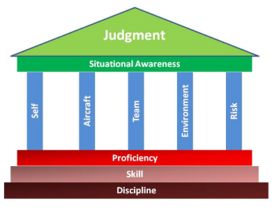 4.7.1 What is airmanship? The definition of airmanship is somewhat indistinct. With the introduction of computerised control systems, the application of airmanship is certainly more broadly based and complex now than 50 years ago. Some might say it involves pilot proficiency, flight discipline, aircraft system and airworthiness knowledge, and skill in resource management, plus being fully cognisant of every situation and exercising excellent judgement. A few years ago someone did say — in relation to the management of airline transport aircraft — airmanship is "the ability to act wisely in the conduct of flight operations under difficult conditions". If that is valid then the three-pilot flight-deck crew of Air France Flight 447, with 20 000 flight hours experience, failed their crucial airmanship test on June 1, 2009. The author's definition is reasonably applicable to sport and recreational aviation: Good airmanship is that indefinable something, perhaps just a state of mind, that separates the superior airman/airwoman from the average. It is not particularly a measure of skill or technique, nor is it just common sense (i.e. the normal understanding and judgement we should all have). Rather, it is a measure of a person's accumulated learning — their knowledge and awareness of the aircraft and its flight environment, and of their own capabilities and behavioural characteristics; combined with good judgement, wise decision-making and attention to detail in the application of that learning; plus a high sense of self-discipline. Airmanship is the cornerstone of pilot competency. Competency has been defined as the combination of knowledge, skills and attitude required to perform a task well or to operate an aircraft safely — in all foreseeable situations. For example, here is an extract from an RA-Aus incident report: "The aircraft, with instructor and student on board, was returning to the airfield when a pitch-down occurred. Not known to them the elevator control horn assembly had failed. Control stick and trim inputs failed to correct the situation, but a reduction in power did have some influence, though not enough to regain level flight. A satisfactory flight condition was achieved by the pilots pushing their bodies back as far as possible and hanging their arms rearward. A successful landing at the airfield was accomplished." A flight operation, even in the most basic low-momentum ultralight, is a complex interaction of pilot, machine, maintenance, practical physics, airspace structures, traffic, weather, planning and risk. When every flight is undertaken, it is not only the aircraft that should be airworthy; the total environment — flight planning, airframe, engine, avionics, atmospheric conditions, pilot condition and aircraft handling — should allow for the safe, successful conclusion of each operation. It is the perception — founded on the acquired underpinning knowledge — of the state of that overall flight environment and its potential threats that provides the basis for good airmanship and safe, efficient, error-free flight. Insufficient perception and insufficient self-discipline create a pilot at risk. The bulk of sport and recreational aviation is undertaken by 'amateur' pilots (using the original meaning of the term; i.e. a lover of a particular activity or pastime), but such pilots must still approach aviation with the continuing diligence of a professional. Less experienced pilots must acquire levels of airmanship consistent with their progress along the aviation learning curve. Ensuring engine and/or airframe airworthiness prior to flight is a prime component of airmanship. Owner-pilots are totally responsible for the continuing maintenance of their aircraft, be it a hang glider or a high performance aeroplane. However — for the person accepting an aircraft they do not own/operate — airworthiness, unfortunately, is a matter of faith in the operator, and in the accuracy and completeness of the aircraft's maintenance record. Daily inspections and pre-flight checks cannot assure airworthiness — the pilot does not know what is hidden under the skin or within the engine. Just as the term 'seamanship' implies a full appreciation of surface wave action and sea movement, so 'airmanship' implies a full appreciation of atmospheric waves, eddies, thermal activity and turbulence. 4.7.2 Risk management Most sport and recreational pilots accumulate only a small number of hours each year; about two-thirds of powered aircraft fly less than 60 hours. Perhaps such annual hours is enough to maintain physical flying skills learned at the ab initio flight school — if the pilot has established a program for self-maintenance of that level of proficiency — but maybe not enough to maintain a high level of cognitive skills; for example, situation awareness, judgement and action formulation. In addition, having completed flight theory studies sufficient to pass the basic aeronautical knowledge test and achieve the RAAO's Pilot Certificate, it seems that many, perhaps most, pilots leave it at that — so failing to expand their knowledge by further in-depth studies of flight dynamics and the application of the acquired knowledge; possibly because it involves sometimes difficult detail rather than the broad-brush approach of the flight school. Or, perhaps, assuming that the necessary knowledge will be acquired through subsequent flight experience, also assuming (I guess) that they will survive every learning experience in a condition to continue flying. However, many pilots are just continually repeating the same flight experience — each year is the same as the last — so all they accumulate is a repetition of one year's experience. They have no program of deliberately advancing knowledge and skills, nor have they really absorbed the safety basics that should have been drummed into them over the years — never turn back following EFATO; always maintain a safe airspeed; if the engine has been misbehaving never take off until the problem is identified and fixed; if the engine goes sick in flight don't try to make it back to base, land ASAP; don't continue into marginal conditions — turn back; and so on. So a safety problem exists with some pilots. Many are just not ensuring that they accumulate adequate post-certificate knowledge and skills. In short, they never really learn much about flight dynamics and the atmosphere (and some of their accumulated beliefs are dangerously false); they lack other pertinent knowledge; and worse, they are just not listening or hearing. Be assured that every pilot needs to know more. The sound pilot must understand how the environmental parts relate and interact with each other, and judge the likely consequences of any action, deliberate non-action or random event. A systematic approach to continuing improvement in airmanship, plus an ability for self-appraisal, is necessary to achieve that understanding. The Flight Manual or Pilot's Operating Handbook for the powered aircraft model being flown must be fully understood, and the content recollectable when needed in an emergency. Every flight should be conducted correctly and precisely, using procedures appropriate to the airspace class and without taking shortcuts, even if just a couple of circuits and landings are contemplated. To paraphrase Louis Pasteur's 1754 observation: 'Chance favours only those who have prepared'. Pilots should be aware that fatigue, anxiety, emotional state — or flying an aircraft that stretches their skill level or just flying an aircraft they don't like — will affect perception and good judgement. See the "I'M SAFE" checklist. Most studies of aircraft accidents or incidents reveal not a single cause but a series of interrelated events or actions that, being allowed to progress without appropriate intervention from someone, lead to an unplanned termination of the flight. A U.S. Navy pilot once wrote "In aviation you very rarely get your head bitten off by a tiger — you usually get nibbled to death by ducks." However, U.S. Navy pilots are well-trained, well-informed, self-disciplined individuals who do not expose themselves to those situations where eventually the tiger WILL bite your head off. Many years ago, the gliding community demonstrated that there were two main cyclic periods (for them) where people were accident prone. This was about the 100-hour mark, where pilots were beginning to think they were immortal, and about 200–250 hours when they were sure they were; being survivors of the incidents of the first period. Dr Rob Lee, the then Director of the Australian Bureau of Air Safety Investigation, wrote in 1998: "Over 40 years of investigation of General Aviation accidents by BASI and its predecessors clearly shows that while the immediate circumstances of each accident may well be unique, the underlying factors are always drawn from the same disturbingly familiar cluster — pre-flight preparation and planning, decision making, perception, judgement, fuel management and handling skills". A study of the factors contributing to fatal general aviation accidents in Australia for the ten years 1991–2000 showed that inadequate flight planning was a factor in 38% of the accidents, aircraft handling errors in 30%, and fuel starvation or exhaustion in 10%. 4.7.3 Situation awareness (The Australian Civil Aviation Safety Authority's 2009 publication 'Safety behaviours - work book for pilots' © CASA includes airmanship and situation awareness text from this page.) Being situationally aware means to be fully cognisant of the big picture at all times, by continually collecting and judging information from sources inside and outside the cockpit. In flight, a pilot has to be thinking several minutes ahead of the aircraft, not several seconds behind it — to perceive what's going on and be able to impose sound judgement on every change, from a minor distraction to a major in-flight emergency. Stress may build rapidly in an emergency situation and the pilot will tend to unconsciously focus on a very few aspects of the situation, without noticing that other aspects are degrading — airspeed or attitude for example. Good handling of any unusual situation — particularly the first major emergency — provides a basis for confidence in abilities. Poor handling of an emergency will undermine confidence. (Note: I have used the term 'situation awareness' throughout the various guides rather than the more commonly seen 'situational awareness'. This is to accord with the official documents CAAP 5.59-1(0) , CAAP 5.81-1(0) and the CASA day VFR syllabus – aeroplanes (PPL and CPL). CAAPs provide recommendations and guidance to illustrate a method, or several methods by which legislative requirements may be met. ... JB) There is much written on the ways to improve situation awareness but it boils down to a few basics: Assimilate an adequate knowledge base. To enable appropriate judgements and manage threats — or your errors — you must have sufficient underpinning knowledge of all relative aspects of flight, of human limitations and of the aircraft you are flying. Plan well in advance with a properly researched weather forecast and flight plan. Pre-flight planning may start days before a flight. Even local flying should be preceded by looking at a met forecast the evening before — to compare against the conditions you find and how the sky really looks. You must know the aircraft's take-off and landing capability in the existing or expected environment. Continually monitor flight progress against that plan, re-evaluating where necessary and implementing alternatives as soon as the need becomes apparent. Develop and use a scanning technique that takes in engine instrument indications, flight instrument indications, aircraft heading, flight path (60° left, ahead, 60° right, above, below), time, map and ground. Develop a scanning pattern that covers everything without becoming superficial but also allows time to be allocated to individual scan segments according to your perceived needs. For scanning techniques read 'Eye on the sky' in the September – October 2003 issue of Flight Safety Australia. For a research report on the limitations of the VFR unalerted 'see-and-avoid' principle read this 1991 ATSB report. For a description of the pilot's role in collision avoidance read the FAA advisory circular AC90-48C. Project ahead and rehearse your actions — for example: "The next checkpoint will be in sight in …" "If the next checkpoint doesn't appear as scheduled I will … " "If the cloud is not as high as it appears or there is more of it than there appears I will …" "If an aircraft appears on a straight-in approach I will …" "If the engine packs up soon after lift-off I will …" "If the engine packs up above 200 feet I will …" Avoid locking on to a problem, a task — or, for instance, your intended landing point — for too long, don't keep your head in the office, keep the scan going, be aware of the relative position and movement of other traffic, hold the heading and fly the aircraft at a safe airspeed appropriate to current atmospheric conditions and your height above the surface and obstructions. When operating at or in the vicinity of airfields, use a radio transceiver to communicate your position and intentions to other aircraft. Listen out for those key words that indicate other aircrafts' positions and intentions. Be aware that not all aircraft will be radio-equipped and even those that are may not be listening out on the appropriate frequency. Project ahead to plan safe and orderly traffic separation — most light aircraft mid-air collisions and near-misses occur in the vicinity of an airfield. In short — be well informed, plan well in advance, fly to that plan, continually monitor flight progress, use a scanning technique and be aware. Know where all other aircraft are and their intentions, communicate when appropriate, project ahead and, above all, don't be distracted — fly the aircraft and fly it at a safe speed and within your limits and the aircraft's performance limits. 4.7.4 Self-discipline The reason for choosing to ignore the established rules is usually to save time or money, coupled with the belief that they will get away with it because 'It can't happen to me' or 'It'll be okay'. Sometimes, particularly when they flout the laws of physics or aerodynamics, it is either pure bravado or wanton disregard (i.e. plain stupidity), or maybe it is just lack of knowledge. There are — fortunately only a few — rogue pilots in the various aviation communities who believe that the rules, written or otherwise, are stupid or unnecessary, and so determine to flout them. Such people ignore the trail of injury and death, stretching back over most of the 20th century, which formulated the rules and conventions. Each conscious infraction of those rules further dulls good judgement until crunch time finally arrives and, unfortunately, such rogues often take others with them. All pilots have a moral responsibility to inform a passenger, intending to fly with a person known to engage in illegal or doubtful activities (e.g. unauthorised low flying or inappropriate manoeuvres around the airfield), that flight with that person is inadvisable. If a person is known to consistently indulge in illegal or dangerous flight then there is a responsibility to inform an appropriate authority — police, CASA, RA-Aus, HGFA, etc. All pilots must occasionally ask themselves the question: Am I maintaining a fully disciplined approach to all flight and pre-flight procedures? And if not — why? Good airmanship cannot co-exist with poor discipline. A self-evident truth is that a pilot lacking the appropriate self-discipline is an accident in preparation. Discipline overrides panic and reinforces the ability to maintain/regain control of the aircraft when faced with a serious flight situation. 4.7.5 Rules, regulations and common sense Not even the most experienced pilot, flying maximum hours every year, can judge the probability of all likely outcomes in any situation, expected or unexpected, and make the appropriate decisions. For that reason, among others, a system of regulations, rules, conventions, practices and standard procedures exists for recreational and sport aviation — and all other aviation communities — to follow. Once acquainted with them, these rules and procedures, plus commonsense practicality, generally provide an acceptable level of protection. But far too often, pilots and others — all of whom should know better — deliberately choose not to follow them and thus abandon that inherent protection. 4.7.6 Personal operating procedures Standard operating procedures (e.g. joining the circuit, completing a flight note) are not included in the RA-Aus Operations Manual. However, every pilot should develop and follow their own set of personal operating procedures and apply them, where applicable, to each flight operation: e.g. a procedure to be followed if unsure of position on a cross-country flight; or turn-back if you find yourself flying toward rising terrain and a lowering cloud base; or having the self-discipline, when under time or other pressures, to decide whether you should take-off in the first place! If there is doubt about the weather, the wise pilot leaves the sky to the IFR-rated pilot in the IFR-rated aircraft. A non-IFR pilot caught out in instrument meteorological conditions [IMC], or dark night conditions, will be very lucky to survive. The dedicated pilot flies accurately, using approved technique, knowing the performance (i.e. the best rate) airspeeds for the aircraft being flown and consistently maintaining such airspeeds — and the chosen altitudes and headings. She or he will know the minimum safe speeds for various angles of bank when turning in level, climbing and descending flight — and at varying weights and cg positions. The pilot will know the aircraft's glide performance and, during flight, will be continually monitoring the ground for possible safe landing sites should the engine fail. Such pilots will have developed a set of tolerances for personal performance assessment; e.g. airspeed consistently within 5 knots, altitude within 100 feet or heading held within 5°. The dedicated airman or airwoman aims to fly with style, making smooth, timely and balanced transitions when turning, climbing, descending or levelling off so that the flight path flows, rather than being seen as a string of loosely connected manoeuvres. Every landing is a gentle arrival that doesn't strain any part of the aircraft. 4.7.7 Human factors training The term 'pilot error' appears extensively in safety investigation reports but is generally a most unsatisfactory summation of an event and its causal factors. In the 1980s the International Civil Aviation Organization [ICAO], the administrative authority for the world's international air transport system, finally accepted the inevitability of human failure in flight, maintenance and other aviation operations. Consequently, in the late 1980s ICAO introduced 'human factors' [HF] training and assessment requirements for pilots (and others), and circular 227-AN/136 'Training of operational personnel in human factors' was issued. Effective August 2008, RA-Aus introduced human factors training to the flight training syllabus; consequently, from August 2008, all student pilots study HF in their training and, by 31 August 2010, all existing Pilot Certificate holders must complete an RA-Aus HF course or pass the RA-Aus written HF examination, or show other evidence of meeting the required competencies of the RA-Aus Operations Manual, section 3.09. The Australian Civil Aviation Safety Authority [CASA] also decided that, from 1 July 2009, threat and error management will be added to the existing human factor aeronautical knowledge examinations within their day VFR syllabus. The Civil Aviation Advisory Publication CAAP 5.59-1(0) 'Teaching and assessing single-pilot human factors and threat and error management' was published in October 2008 and is recommended reading. CAAP 5.59-1 links human factors with deficiencies in airmanship. The CAAP defines human factors as 'Optimising safe flight operations by enhancing the relationships between people, activities and equipment. This means: achieving the safest outcome for flight operations by the most effective use of people, and what people do when operating in the aviation environment and the equipment they use.' The 2009 CASA safety behaviours publication 'Safety behaviours: Human Factors for Pilots' is available. The pack consists of: Safety behaviours – resource guide for pilots (183 pages plus a CD) Safety behaviours – work-book for pilots (111 pages) Safety behaviours – facilitator's guide (15 pages) Guidance material – extract from CAAP 5.59-1(0) (42 pages) The pack can be purchased from the CASA online store for the cost of postage (one copy per person only). Further reading The online version of CASA's magazine Flight Safety Australia contains some articles relating to airmanship, which are recommended reading. A categorised index of articles of interest to recreational pilots contained in Flight Safety Australia since 1998 is available on this site. The articles are listed within ten categories together with a very short summary of the content. 4.7.8 A CFI's viewpoint The late Tony Hayes, once CFI of Brisbane Valley Leisure Aviation Centre — and the inaugural holder of the RA-Aus Meritorious Service Award — published this airmanship interpretation. "Airmanship — aviation could not exist in a responsible manner without this apparently intangible component. Let us define airmanship exactly so you do know what you are searching for to make your own, and thus achieve personal protection, pride, and protection of others, in your own standards of what you do, or propose to do. The big intangible is our personal attitude to flying — why we do it, how we do it. Do you care to define an individual's personal attitude to both flying and the environment in which that person's flying is conducted? Many things form our attitudes and we need to consider these if we wish to see airmanship as it really is — get a handle on it and make it our own. That is easy enough, but before we start — accept that airmanship is something that grows. It grows on experience whether shaped by training or by personal exposure to what you do. You cannot learn airmanship only from a book or an instructor, you are as much guided there by exposure to those circumstances, encountered with growing experience, which require airmanship. Whether it be flying training or airworthiness training — only the basics can be established. Like the runner in a relay race taking the baton — you have the potential winning element in your hand, it is up to you if you win or not, take on what you have been given, and make it work for both yourself and the others with whom you share the skies. Winning the airmanship race is not simply about staying alive or not bending yourself or aircraft — it is walking off the airfield relaxed, knowing you have not simply performed but have crafted an activity, and being totally aware you have enjoyed the sum of that and owe nothing to anyone. Let us start with a target to shoot for. Airmanship — a definition 'A personal and situational management state required to allow a human being to enter and exit, in safety, an environment which they were not naturally designed to inhabit. This state comes into being immediately a decision is made that an aircraft is going to be flown and continues until you walk away from the completed flight and correctly secured aircraft.' That continuation may require an instinctive willingness to assess, between flights, the lessons that have been stated by the flight just completed. Airmanship is as much a ground-based attitude as it is an air-based one. Airmanship structure We are now going to look at the basics upon which airmanship is formed and therefore can be understood. We have already touched upon one — PERSONAL ATTITUDE — now we must put this in context with the others: KNOWLEDGE — SKILL — CONFIDENCE — RESPONSIBILITY. These four are then applied by personal attitude. The application of airmanship can be defined to three areas: the airworthiness of the aircraft the operation of the aircraft and the environment in which the aircraft operates. We will briefly examine each of these requirements and applications. All four requirements are intimately interconnected with each other and with applications, so cannot be treated entirely as stand-alone subjects. Knowledge • AIRWORTHINESS. You do not have to be a mechanical engineer to be a pilot but you do need to know sufficient about the aircraft structure and systems to enable you to safely pre-flight it and adequately monitor its continued satisfactory operation. The degree of knowledge required will depend upon the complexity of the machine and the range of environments in which the machine is capable of operation. (See the 'home builder' comment below.) As pilots do not have to be engineers, there is therefore a supporting mechanical and engineering system to which the pilot will generally interface, via documentation, which revolve around periodic servicing and in-service defect reports. Understanding this system is part of the knowledge requirement such that you do appreciate whether the aircraft is provisionally serviceable or not — subject to pilot inspection. • OPERATIONS. These are very much the pilot's responsibility and sufficient knowledge must be present for the safe operation of the aircraft within the parameters for which it has been designed. This knowledge must extend adequately from flight principles through to understanding of systems operation. All of this must then interface with the environment within which the aircraft will operate and this in turn requires understanding and application of airspeed limitations, manoeuvres permitted, weather minima (e.g. maximum crosswind limits), etc. • ENVIRONMENT — Meteorology. The forces exerted by the ever-changing atmosphere upon an aircraft are far removed from those weather considerations we have knowledge of when we exist only on the ground. The pilot has to be able to read the sky like an advertisement, interpret current conditions and identify changing conditions along with the rate and degree of change. Decisions so made then have to be balanced with aircraft operational limits and the pilot's personal skill limits — usually this is a forecast being responded to before the situation has moved beyond estimated limitations. — Behaviour controls. In simple terms this is knowing the 'rules of the road' in terms of rules of the air. From simple basics such as 'give way' rules, to airfield marking systems, to airspace restrictions — these are all designed to enable the present huge variety of aircraft to share airspace safely. They must be understood and instinctively applied by the pilot. — Regulation. Partly from lessons learnt the hard way in the past, and partly due to an ever expanding population both in the air and on the ground — the information resource of who does what to whom is bound into regulation. The pilot needs to know this regulation as applicable to his or her operation, respect that others have different parameters they must follow and make allowance accordingly, plus have the regulation available and currently updated to suit the operations being conducted. Skill This is an area determined, at least on the surface, by our ability to perform certain actions and procedures. But you can teach a bird to talk — that does not mean the bird understands what it is doing or can hold a conversation. Skill is underpinned entirely by knowledge and from this skill may be put in context and is capable of organised development based upon growing experience. • AIRWORTHINESS. The degree of skill in this area depends upon the level of airworthiness control you intend to apply. In pilot pre-flight terms, the skill will be certainly underpinned by a healthy element of curiosity — does it actually work and is it likely to stay in place! As we move further into servicing and repair, then hand and machine skills (adequately supported by appropriate knowledge) increase. For both control and convenience, divisions are made as to the degree of work which may be undertaken via various airworthiness maintenance approvals, each requiring higher knowledge and skill levels. • OPERATIONS. As the aircraft you have access to become more complex then so the further you are removed from basic stick and rudder skills to new skills that are mainly founded upon systems operation and changing operating parameters. Those basic skills have to be totally and automatically in place, with sufficient competence of application supported by knowledge, such that the new skills may be safely founded. With this foundation, you may move from a simple aircraft to a slightly more complex one with some confidence and further acquisition of systems and operating parameters — but you should instinctively stop if you are clearly going beyond your existing knowledge and skill base until you have corrected that situation. There is another element to skill and that is currency. None of us, no matter how much we have flown, are any better than our next arrival on the ground. If we are not current (particularly with more complex aircraft, which require confident fluidity in the checks and procedures with their operation) then we could just be rolling the dice on the basis of 'been there, done that — she'll be right'. But even the simplest of aircraft will severely bite the 'out of practice' pilot. How much out of practice is 'out of practice'? The airman instinctively knows. Situational appraisal, how long out of practice, so many other things — all come into play here. As a command pilot, the airman will make a valid decision based on information and assessment, and react accordingly and safely. • ENVIRONMENT. In this situation we are less concerned about the tirades of the weather (although that has an obvious control upon how skill is intended to be employed). In airmanship terms we are more interested in the human environment of peer group pressure, personal needs to achieve a task, or (for some pilots) pressure applied by employers. Too often, a flight becomes driven by emotive pressure and/or need to complete a flight for personal gain (in so many forms). Emotion and personal gain are the two biggest killers yet invented by our race. Every year the figures continue going on the board in terms of deaths and wrecked aircraft — ran out of fuel, weather out of parameters, flew into lowering cloud base and rising ground. It still happens every year! As human beings we are never more vulnerable than when our skill is being questioned or challenged by others — or even ourselves, particularly in situations where by its very nature flying begins being interpreted as some 'personal courage combined with ability' thing. The true airman, with knowledge present and supporting skill in place, is dispassionate and evaluates situations on known and observed circumstances. Too often for some, tomorrow may indeed have been soon enough, but was not! Confidence Confidence can be underpinned by one simple control statement — 'If in doubt, don't'. If there is doubt, then confidence by definition does not exist. If you are not confident then you should not go. Confidence is formed by adequate levels of knowledge and skill. The airman has these in constant balance and sees a flagging of confidence as a natural warning bell — there is yet more work or revision to be done so that confidence is truly there. When those warning bells sound then it does not matter if the doubt concerns whether the aircraft is serviceable, or if you are up to the flying you are undertaking — time to take pause and look for additional abilities. There is also another element to confidence, and that is overconfidence. In this situation, even adequate knowledge and skill is being superseded by an emotive form of confidence. Once with a Pilot's Certificate achieved, the need to satisfy an instructor's discipline may fade, knowledge becomes steadily forgotten as a stimulus to what must be, and skill currency may go the same way. With the demand strictures of flying training now past, near enough may be good enough — forgotten is the need for why those original standards were set. Overconfidence meets its true ground in exhibitionist flying. In this situation the pilot is driven by ego, deliberately in front of an audience (which is mandatory) to show they are more than mortal and can really 'fly'. Unfortunately, the accident records confirm that such people are indeed mortal. Those tend to be the 'headlines' examples — but the run-of-the-mill situations are the greater number of people who bend themselves and/or aircraft — or — the much larger majority who narrowly avoid disaster, and hopefully become airmen as a result of that new demonstration of their inadequacy. Responsibility If confidence cannot exist without knowledge and skill then the exercise of responsibility cannot exist without all three. Here the airmanship pattern may be disrupted and two opposites meet. A totally trained, knowledgeable and skilled pilot, under the influence of irresponsible behaviour, can be as discounted as the worst non trained aerial lout. Ultimately we are human. We are subject to human drives. So maybe there is another definition to airmanship — the self-discipline and wisdom to rise above our human condition and just be practical about what we do and where we do it. Homebuilders Within the ultralight community we have a sector of effort which is, via particularly CAO 95.10, but within overtones of 'amateur built' — an area where airmanship principles themselves may be seen by reflection. In this area, the intending pilot does have to embrace sufficient elements of the designer, engineer and aircraft constructor. The requirements for knowledge and skill are self-evident. Confidence will ultimately be expressed by a preparedness to fly the finished machine. Responsibility will be expressed by understanding that sufficient knowledge and skill was present to build the machine to an airworthy standard, but there is also equal knowledge and skill present in the operations area to ensure that the proving flights are conducted safely, responsibly and with validity. Near enough is never good enough on a new aircraft type. So the ultimate definition of airmanship, when seen in context with allied disciplines, comes down to quality of performance within prevailing circumstances — backed by quality of personal intent. Flying is fun — a pile of wreckage is neither. Between those two extremes is the ultimate expression of airmanship." The following document is an extract from the BVLAC flying training manual written by the late Tony Hayes. (The flying school has since ceased operations.) "For all my exposure to aviation — which extends over my entire life from my birth next to an operational bomber airfield in World War 2 — when I came to pilot training myself I met a term so commonly used yet nowhere could I find actually defined and explained, Airmanship. So I will fix that right now in my own flying training manual. The problem is understood once Airmanship itself is actually understood. It is very real and manifestations of it may be seen at every airfield or places people come to fly aircraft. Yet Airmanship is an intangible, for it is a state of mind, personal convictions and self discipline expressed in our actions and attitudes. It is the prudent operation of a machine, and the management of circumstances surrounding that operation, within an element we were not naturally designed to inhabit. Airmanship appears in every flying area and sets aside the airman from the aircraft driver. It is founded firmly in basic training where mental attitudes to flying are forged, and sometimes in self training where a pilot learns the hard way about what is prudent or not, gets away with it, and elects to make more sensible decisions at the right time, next time. Under growing experience airmanship may grow and blossom into a comfortable protective cloak, resting light upon the shoulders, worn perhaps with pride, but never in vanity, and giving the protection of 2 inch armour plate. The very need for its presence is a reminder that we are privileged to transit from our natural element into another. There may be a high price for such transition if that act is made in scorn or ignorance. But we may go there safely if we acknowledge the limitations of ourselves and our machines, so generating a curious mixture of humility and confidence which is expressed in the very form of airmanship. Airmanship may be performing a proper pre-flight check of an aircraft rather than a casual look-around. It is something as instinctively looking before turning. It is actually doing pre take-off and pre-landing checks — not mouthing the words. It is sensible pre-flight planning — either for a circuit or going over the horizon. It may be as simple as looking at the windsock before hitting the 'loud' lever, or as complex as interpreting a changing weather pattern. It is the essential personal and situational management difference between being up there wishing you were down here, rather than being down here wishing you were up there. But, founded on flawed training, or growing experience driven by a different pride, airmanship may wither into a deadly weed of contempt for those who slavishly obey 'regulation' or are not deemed 'good enough' to sort out situations as they happen. People driven by such views, in their ignorance, inhabit a perilous place of their own making wherein they have become an accident looking for somewhere to happen, and so ensure that it will happen. The non-airman will discount that the 'officious regulation' is (in the main) a book written in the blood of people who found out the hard way and handed down to us methods of avoiding their fate. In discarding that knowledge so is generated the certainty of the same fate, standing in the shadows, waiting. The airman is a person who maintains a valid skill and knowledge currency such that when the unexpected does happen there is ability and composure enough to manage the situation into safety. He or she, is a person with a sense of balance and intelligence enough to heed the lessons of the past, apply them in the present, and so ensure a future to be able to fly again, and again, and again. You will be hearing a great deal more about airmanship in your time with us, and now you know what we are actually talking about." — Tony Hayes, CFI; Brisbane Valley Leisure Aviation Centre STRICT COPYRIGHT JOHN BRANDON AND RECREATIONAL FLYING (.com)
 -
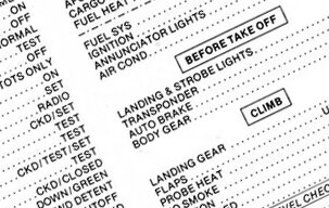 4.6.1 Being prepared for an emergency There is always a possibility of an en route engine problem, or other event, necessitating an off-airfield landing. A reasonable knowledge is required of the procedures with such incidents, particularly those occurring in remote areas and you should have an emergency check list readily available in flight. Read the 'Coping with emergencies' guide. Before departure it is certainly wise — if not mandatory — to leave enough information with a responsible person, so if you fail to check in with them by an agreed time a telephone ring-around can be initiated. If that is unsuccessful the Rescue Coordination Centre of the Australian Search and Rescue organisation [AusSAR] can be notified. AusSAR will attempt to make contact with the missing aircraft. If that is also unsuccessful AusSAR will initiate a search that uses your planned track as a starting point. The information that AusSAR requires is contained in the flight note form recommended by the Australian Maritime Safety Authority [AMSA]. AusSAR is a division of AMSA. For further information on communications when in difficulties, the legal requirement to carry a 406.025 MHz ELT, AusSAR ELT monitoring and search procedures; refer to the 'Safety and emergency communication procedures' in the VHF radiocommunications guide. 4.6.2 Planning and equipment check list There are several civil aviation regulations (a copy of which can be viewed at Some noteworthy sections of the Civil Aviation Act 1988, the CAR 1988 and the CASR 1998) that direct pilot actions before flight. These regulations are CAR 78 'Navigation logs', CAR 92 'Use of aerodromes', CAR 233 'Responsibility of pilot in command before flight', CAR 234 'Fuel requirements', CAR 235 'Take-off and landing of aircraft etc', CAR 235A 'Minimum runway width', CAR 239 'Planning of flight by pilot in command', CAR 244 'Safety precautions before take-off' and CAR 282 'Offences in relation to licences, certificates and authorities'. The requirement for two-place aeroplanes to carry an approved emergency locator transmitter is stated in CAR 252A; single-seat aircraft are exempt from that requirement but it's certainly wise for all aeroplanes to carry an ELT. In addition CAR 232 'Flight check system' requires provision of procedural check lists and the pilot must ensure that the check lists are carried in the aircraft. Note that CASA EX38/2004 exempts owners/operators of aircraft with a MTOW under 5700 kg from compliance with the requirement to obtain prior CASA approval of those flight check systems. It is advisable to run through a flight planning, navigation equipment and aircraft equipment check to ensure that all requirements have been covered. So, have you: established the safest route and minimum safe altitude; avoiding rough or heavily forested terrain, designated remote areas, other hazardous areas, restricted areas and CTA/CTR — or airspace where a functioning Mode C/S transponder is mandatory — and marked that route on the paper or digital chart you will use in flight? double checked that all magnetic bearings and distances on the flight plan have been measured and recorded correctly? checked the locations and the suitability of refuelling stops, of the destination airfield and of alternate landing areas? checked their details in ERSA including ASIC requirements and the landing charges applicable? For airfields not listed in ERSA have you checked with the owner/operator about the airfield dimensions, slope, condition, approach and departure terrain limitations, animals, tree heights, power lines and other obstructions/hazards? Is your skill level sufficient to safely land and take-off at those airfields? checked the en route, destination and alternate airfields' weather, cloud base and visibility (ARFOR, TAFs, METARS and surface chart), end of daylight (bearing in mind the effect of forecast cloud conditions on visibility) and NOTAM (ADs, ALAs plus restricted area and military low jet route status)? checked the BoM weather radars and other internet lightning tracker sites? left a flight note — showing the itinerary and the information required by the Rescue Coordination Centre — with a responsible person who knows what action to take if you fail to check in by the agreed time? checked that watch, compass, ASI and altimeter function okay and that nothing is placed in such proximity that compass operation will be affected? checked that the VHF transceiver is functional and noted/loaded all the required frequencies? checked that the 406 MHz ELT battery is functional, not past the replacement date and that the AMSA registration sticker is current and attached to the device? Shown your passenger how to operate the ELT/EPIRB and firmly attached the device to your body? provided back-up batteries for handheld equipment? life jackets donned, if any part of the flight is over water? decided whether to take an inflatable life raft with emergency survival kit? provided a first aid kit in the aircraft and a helmet for your passenger? demonstrated the intercom system to your passenger? ensured that your passenger is: (a) familiar with the safe operation of the seat, seat-belt, safety harness and the cockpit door and (b) knows to keep their feet off the rudder pedals and not to grab the controls if startled? if intending to carry a child as the passenger, provided an adequate child restraint system plus an appropriate protective helmet? Have you considered whether any child would be legally regarded as a risk-informed participant? selected clothing suitable for the surface conditions, in case of an unplanned landing? packed an extra supply of prescribed medication? provided an adequate fresh water supply in your survival pack? provided additional survival equipment, if operating into a designated remote area shown in ERSA GEN-FIS 'Designated remote areas' or on VNCs? loaded tie-down gear securely? checked that the Aircraft Flight Manual/Pilot's Operating Handbook, cockpit check lists and flight plan, plus all the associated Airservices Australia documents and publications, are current and on board? If the aeroplane is an LSA check that a copy of the CoA and Statement of Conformity is in the aircraft flight manual. (Maps, check lists, AFM/POH and flight plan could be digitally stored in an appropriate and approved electronic flight bag, but see 'Electronic flight planning & the EFB'; the check lists might be stored in an EFIS) physically checked the fuel in the tanks and oil in the engine for suitability, quality and water or other contamination? Stowed the fine fuel filter funnel for en route use? physically confirmed that the actual fuel load provides a reasonable margin — on top of the flight plan needs including the reserve? measured and ensured that aircraft take-off weight and centre of gravity — with everything and everyone loaded — will be within the limits stated in the Aircraft Flight Manual/Pilot's Operating Handbook and retained evidence of the W&B calculation? calculated the density altitude — and the take-off distance required from the Aircraft Flight Manual/Pilot's Operating Handbook to ensure that take-off distance, to clear a 50 feet screen, is amply provided by the dimensions and current condition of the intended runway at the departure airfield? done the same density altitude calculations for the destination and alternate airfields, and ascertained that the effect on landing, take-off, and climb-out performance, at the expected aircraft weights and cg positions, will still provide an adequate safety margin taking into account the forecast weather plus the dimensions and condition of each of those airfields, and including the possibility of a late go-around? 4.6.3 Personal fitness for flight The next check is a personal one, determining if YOU are safe to fly. A mnemonic checklist has been developed for that purpose. Answering 'yes' to any of these questions may mean that your alertness, perception, judgement, general performance or situation awareness capabilities are seriously downgraded; also you are likely to forget to do something that must be done. The I'M SAAFE checklist is: Illness? Do I have an illness or any symptoms of an illness or disorder or a known condition that could present an in-flight hazard? Medication and other drugs? Have I been taking/mixing prescription, over-the-counter or 'recreational' drugs? Stress and distraction? Am I under psychological pressure from the job or personal circumstances? Am I worried about financial matters, health problems, family problems, emotional problems or relationship discord? Am I worried about undertaking this flight? Age? If you are in your later years, have you considered whether your ability to cope quickly and wisely with an emergency or an unfamiliar situation may have reached the point where it would be prudent to be accompanied by another qualified pilot? Alcohol? Have I been consuming alcohol within the previous 8 hours? (Even within 8–16 hours after consumption, blood alcohol levels can be significant. If tested by an authorised person, the permissible blood alcohol reading is less than 0.02, which is to allow for any anomaly caused by — for example — the alcohol (or similar) content of some medical preparations. Would my average alcohol consumption be classified at greater than 'very low risk'? Fatigue? Am I tired, inadequately rested or suffering from lack of sleep? Eating and drinking? Am I inadequately nourished and/or dehydrated? There are several articles, contained in the online version of CASA's magazine Flight Safety Australia, which are recommended reading. See the section titled 'Aviation medicine' in our index to those magazine articles. 4.6.4 Staying within the rules Carriage of passengers Prior to flying an LSA-certificated aircraft, the pilot must inform the passenger that the aircraft does not meet the same airworthiness requirements as an aircraft with a Standard Certificate of Airworthiness. Note: sport and recreational aviators, and the single passenger allowed, are defined by CASA (only in the aviation regulatory sense) as 'informed participants' in the activity being pursued. An informed participant is aware of the risks involved in a particular form of sport and recreational aviation and is willing to accept those risks. How do you make your passenger aware of the potential risks inherent in sport and recreational aviation so he/she can make a risk-informed decision about their participation? Various warning placards must be displayed in the aircraft cockpit but that's hardly sufficient. What if the passenger is legally a child, how can any child be considered a 'risk-informed' participant? Legally, pilots have a duty of care toward their passenger and may not take needless risks or act in an irrational manner. If you intend carrying a passenger have you performed at least three take-offs and landings within the last 90 days? See the RA-Aus Operations Manual section 2.07 para. 11. Passenger care: please read the RA-Aus Operations Manager's advice on passenger care, appearing in the July 2013 issue of the RA-Aus journal 'Sport Pilot'. Aircraft fitness for flight The Technical Manual section 4.2.1 requires that, before departure, the pilot-in-command must ensure that the aircraft is correctly maintained (by reference to the aircraft log book), the daily inspection has been completed, the RA-Aus registration card is in place and current and the aircraft's fitness for flight has been confirmed by means of a personal pre-flight inspection. Carriage of flight documentation CAR 233 (1) (h) states that 'Pilots are required to carry, and have readily accessible in the aircraft, the latest editions of the aeronautical maps, charts and other aeronautical information and instructions, published in AIP, or by an organisation approved by CASA, that are applicable to the route to be flown, and any alternative route that may be flown, on that flight'. Currently (December 2013) that means the paper maps and charts from Airservices Australia, not digital maps stored in an iPad or other tablet computer except if the EFB software is from a CASA approved supplier. The 'other aeronautical information' for VFR operations outside controlled airspace would include the current ERSA and relevant ARFORs, TAFs, METAR, NOTAM etc from the NAIPS Internet Service. Note: these requirements are in addition to the regulations mentioned above. CAR 78 states 'The pilot in command of an aircraft shall keep a log of such navigational data as is required to enable him or her to determine the geographical position of the aircraft at any time while the aircraft is in flight' and that 'The log shall be kept in chronological order'. The content of the log is not specified for aircraft operating within Australia however a fuel log facility should also be included. Weight-shift aircraft operating under CAO 95.32 are exempt from the need to maintain a navigational log. CAR 139 nominates other documents (aircraft maintenance release, aircraft flight manual, pilot licence, medical certificate) to be carried in flight, however sport and recreational aircraft operating under CAOs 95.10, 95.32 or 95.55 are exempt from complying with CAR 139. The RA-Aus Operations Manual section 2.01 requires pilots to carry their Pilot Certificate and produce it on demand from an RA-Aus official, a CASA official or a police officer; but there is no requirement (for non-LSA aircraft) in the RA-Aus Technical or Operations Manuals that mandates carriage of other documents except the aircraft registration renewal card. LSA aircraft are also required to carry at least a copy of their Special CoA, Statement of Compliance, weight and balance information under the requirements of the Technical Manual section 7.5.3(7). There is no requirement in the regulations or the RA-Aus Operations Manual for pilots to carry their personal logbook in flight, however, you may find it useful to carry a copy of the logbook notation of the successful completion of a still current flight review and, if carrying a passenger, something that confirms the recent experience requirements. The Technical and Operations Manuals require that all pertinent cockpit placards, warnings and other labels, be in place and visible to pilot and passenger. Expect a 'ramp check' inspection Generally RAAO members won't come into contact with CASA officers. However, officers from the Self-administering Sport Aviation Organisations Section do carry out 'ramp check' inspections on pilot and aircraft after landing or before take-off, at any airfield where sport and recreational aircraft are operating. Such operational checks are consistent with the Section's safety surveillance role and are the only means by which the CASA officers can sample the professionalism of the RA-Aus membership and, perhaps, the professionalism of the flight school where the more recently qualified pilots were trained. There is no need for pilots to be fearful or antagonistic — regard the check as an opportunity for a useful learning experience. Those Flying Operations Inspectors might be interested in how the flight has been planned, whether appropriate information available from the NAIPS Internet Service (and from other authoritative sources) has been used and what the navigation/fuel log reveals about how closely the flight conformed with the plan. Other checks might be appropriateness of Pilot Certificate endorsements to the journey, the aircraft type and the carriage of a passenger; evidence on currency of the biennial aeroplane flight review; currency of aircraft registration; cockpit labels/warnings/placards in place plus safety harness conditions and appropriateness. The check might include any of the items listed in the preceding planning and equipment check list but perhaps items 7, 10, 23 and 26 stand out. The Self-administering Sport Aviation Organisations Section produced a ramp check booklet in December 2013 that can be supplied in printed form. CAR 232 'Flight check system' is listed under 'Document references' but as it stands the booklet reference to CAR 232 is a little misleading for aircraft weighing less than 5700 kg, so please read an annotated version of CAR 232 on this website. STRICT COPYRIGHT JOHN BRANDON AND RECREATIONAL FLYING (.com)
 -
 4.5.1 Weather and NOTAM check Area forecast We are planning to depart Oxford for Tottenham around 1400 hrs AEST time on April 30 (0400 UTC) which allows nearly four hours flight time before last light at Tottenham. Shortly before departure time we check the latest area 22 ARFOR briefing material downloaded from Airservices Australia's NAIPS Internet Service. AREA 22 AREA FORECAST AMEND OVERVIEW: FINE APART FROM ISOLATED SHOWERS IN FAR NORTHEAST TILL 11Z. WIND: 2000 5000 7000 10000 14000 18500 070/10 VRB/10 VRB/15 240/15 ZERO 220/15 MS06 210/20 MS15 CLOUD: SCT CU/SC 4500/9000,LOCALLY BKN IN NE TILL 11Z. AMEND WEATHER: SH IN NE. VISIBILITY: 6KM SH. FREEZING LEVEL: 10000 IN SE / 12000 IN NW. ICING: NIL. TURBULENCE: MOD IN CU. AREA QNH 03/07 NW OF YMIA/YMOR 1025, REST 1027 The first part is the general weather forecast for the area as a whole — this states the weather is expected to be fine during the forecast period with some showers in the north-east, which doesn't affect our flight plan region. The wind velocity at 2000 feet amsl will be 070/10 knots and at 5000 feet the speed is shown as 10 knots but the direction is 'variable'. Scattered cumulus and stratocumulus is expected to form with bases no lower than 4500 feet and tops no higher than 9000 feet. The freezing level will be at 10 000 feet so surface temperatures will be mild. The area QNH we will use is 1027 hPa. It looks like a perfect day for flying. Note that it is not mandatory for VFR aircraft to use the area QNH while en route. You may substitute the current local QNH of any aerodrome within 100 nm of the aircraft or, if the local QNH at the departure airfield is not known, you can just set the sub-scale so the altimeter reads the known airfield elevation. Aerodrome weather reports and forecasts If we now look at some actual weather reports [METARs] and the forecasts [TAFs] for airfields in or near our flight region, we can check whether there is any significant variation from the general area forecast. The METAR for our alternate airfield Condobolin, issued at 0300 UTC, reports surface wind velocity 130/7 knots. The TAF, issued two hours earlier at 0107 UTC, forecasts that during the period 0200–1400 UTC the surface wind will be 050/8 knots, the visibility will exceed 10 km (9999 m) and there may be scattered cloud with bases at 4500 feet. There is no weather report for our other alternate. The TAFs are for an area within 5 nm radius of the aerodrome. CONDOBOLIN (YCDO) METAR METAR YCDO 300300Z 13007KT //// 22/04 Q1024 RMK RF00.0/000.0 TAF TAF YCDO 300107Z 0214 05008KT 9999 SCT045 T 19 23 19 15 Q 1027 1025 1025 1026 Be aware that smoke from bushfires or autumn fuel reduction burns can drift over extensive areas and may totally conceal some, or all, landmark(s). Smoke may also dictate flight at a considerably greater altitude than planned and visibility degradation may not appear in the weather forecast. In summer it is advisable to check the state rural fire service website maps for the current fire status. Combined with the area wind forecast it will enable an estimate of the smoke drift. Similar precautions are applicable in the northern dry season. The METAR for Ivanhoe (which doesn't appear on the WAC section shown but is just a few miles west of Oxford) issued at 0300 UTC records a surface wind velocity 120/10 knots. The TAF issued earlier at 0109 UTC, forecasts that during the period 0200–1400 UTC the surface wind will be 080/8 knots, the ceiling and visibility will exceed VMC minima [CAVOK], and from 0800 UTC the wind will shift to 120/10 knots. IVANHOE (YIVO) METAR METAR YIVO 300300Z 12010KT //// 25/10 Q1022 RMK RF00.0/000.0 TAF TAF YIVO 300109Z 0214 08008KT CAVOK FM08 12010KT CAVOK T 24 26 22 19 Q 1024 1023 1023 1024 The METARs and TAFs confirm that, although there is some variation between observed winds and forecast winds. the area forecast is generally representative of the weather in the region we intend to operate. We should also check the 'big picture' — the latest mean sea level analysis or 'surface chart' — issued by the Bureau of Meteorology but which we can obtain from Airservices Australia's NAIPS Internet Service. That chart (below) shows a persistent and strong high pressure system located over south-eastern Australia, which is directing easterly airflows into area 22 and is responsible for the fine weather. The nearest frontal weather is affecting only the south-west corner of the continent. Surface chart I have added the red wind arrows to indicate the surface airflow around the high pressure system. It is the convention that each full barb on wind arrows represents an incremental 10 knots wind speed and a half barb represents 5 knots; thus the wind speeds shown are 25, 15 and 10 knots. (Note that a solid triangular barb on wind charts indicates 50 knots.) Area 22 is located where the 10 knot wind arrow is pointing. Please read the Aviation Meteorology Guide module dealing with southern hemisphere winds. The BoM's aviation weather services provide the latest synoptic surface analysis charts and national forecast charts; area forecasts, TAFs, aviation warnings and a great deal of other information. Wind and temperature forecast charts are available for various flight levels and various times up to 30 hours ahead. To find the wind and temperature charts expand 'aviation charts' and select 'wind and temperature'. The flight levels of interest to recreational pilots are FL050 [5000 feet] and FL100 [10000 feet], note the times are UTC. Using the Aerodrome Weather Information Service [AWIS] While airborne, a radio-equipped aircraft can usually obtain a report of actual weather conditions at the larger aerodromes — see 'Acquiring weather and other information in-flight'. If a mobile 'phone is carried the AWIS (if available) can be used to obtain surface wind and some other weather data. Choosing the cruising level The forecast vertical wind profile indicates there is no cruising altitude which is better suited for an easterly flight than any other. In section 3.5 we determined the lowest safe altitudes were 2000 feet on the first leg and 2500 feet on the others. Thus there is no reason not to plan our flight at the recommended VFR cruising level for an easterly heading (below) of 3500 feet; being below the cloud base it will avoid dodging around scattered clouds. We have to make an estimate of the wind at 3500 feet, which in these light wind conditions will be above the friction layer and, as wind tends to back with height (in the southern hemisphere), we will plan for a wind velocity at 3500 feet of 060/10 knots. Flights operating under the Visual Flight Rules [VFR] outside controlled air space must be operated at levels selected in accordance with the table below when at a height above 5000 feet AMSL, and should be operated at such levels when below 5000 feet whenever practicable. (The cruising levels for aircraft operating under Instrument Flight Rules (IFR) are 500 feet lower.) VFR cruising levels Magnetic tracks 000° to 179° 180° to 359° Cruising altitudes (area QNH) 1500 ft 2500 ft 3500 ft 4500 ft 5500 ft 6500 ft 7500 ft 8500 ft 9500 ft Operating in accordance with the cruising levels does improve safety but pilots should be aware that the risk of collision still exists. For example, consider an aircraft tracking 175°, while to the south another aircraft is tracking 005° at the same correct cruising level. Those two aircraft could well be on a collision course — you must maintain situation awareness throughout all stages of flight. Weather radar The Australian Bureau of Meteorology provides online 'real time' snapshots from about 50 weather radars around Australia. The snapshots are taken at about ten-minute intervals and cover a radius up to 256 km from the antenna. The last four snapshots are retained on the website and can be looped as a progressive image, thus providing an excellent presentation of precipitation and storm movement. Go to the aviation weather services page and select 'Weather Watch Radar Network'. While on the aviation weather services page also have a look at the latest 'Satellite imagery' of the cloud cover over Australia. NOTAM check A check of the NOTAM contained in the area 22 ARFOR briefing material reveals only three that are connected with our planned flight. These three state that the aerodromes are no longer licensed by the Civil Aviation Safety Authority, which is — in effect — a notification that advisory NOTAM aren't issued for those airfields. CONDOBOLIN (YCDO) AD From: 01 090316 To: PERM C0001/02 AD LICENSE WITHDRAWN LAKE CARGELLIGO (YLCG) AD From: 01 090319 To: PERM C0003/02 AD LICENSE WITHDRAWN TOTTENHAM (YTOT) AD From: 01 090317 To: PERM C0001/02 AD LICENSE WITHDRAWN 4.5.2 The set-heading point It is necessary to establish the geographic position, and the point in time, at which navigation will commence after take-off. This set-heading or set-course point should be pre-planned if possible and is usually dependent on the take-off direction, the initial heading and the local environment. If, for example, the take-off direction coincides roughly with the initial heading, and there is no environmental reason to make a turn after take-off, then the set-course point is the take-off point — or very shortly thereafter — and an en route climb technique will be used. However, if the take-off direction is opposite to the initial heading then it is usual to climb out on runway heading until well clear of the circuit area, and at circuit height, then continue climbing in a gentle turn — in the direction of the circuit — that will bring you back over the centre of the airfield, at a height not less than 2000 feet agl, to avoid any aircraft that may be overflying at 1500 feet to join the circuit. Refer to 'The standard circuit pattern'. The set-course point is then overhead the airfield and an en route climb may be indicated if the planned cruising altitude has not yet been reached. Another possibility is to choose an easily identifiable landmark well outside the circuit area as the set-course point. Whichever position is chosen, overhead the airfield or an external location, the flight plan should start from that point and the estimated time required to reach that point should be added to the take-off time allowance in the flight plan. 4.5.3 Heading, ground speed and fuel calculation We plan to cruise at 70 knots CAS and using the rule of thumb that TAS is 1.5% greater than CAS for each 1000 feet of altitude amsl we will increase CAS by 6% to arrive at a TAS of 75 knots at the planned cruising alttude of 3500 feet. That calculation (or perhaps 2% per 1000 feet) is near enough for navigation purposes but it is not actually correct; see the section on density altitude. To complete our flight plan we have to estimate the heading to fly, the ground speed, the flight time for each route segment and the fuel required. We will use the 1-in-60 arithmetic method outlined in section 4.2. Step 1: find the wind correction angle by estimating the angle at which the forecast wind meets the tracks, multiply the result by the wind speed and divide by the aircraft TAS. i.e. WCA = relative angle x wind speed / TAS (a) Segment 1: track = 094° true; w/v = 060/10 knots; relative angle = 34; TAS = 75 knots so WCA = 34 x 10 / 75 = 5°. (b) Segment 2: track = 061° true; w/v = 060/10 knots; relative angle = 1; TAS = 75 knots so WCA = 1 x 10 / 75 = 0°. (c) Segment 3: track = 040° true; w/v = 060/10 knots; relative angle = 20; TAS = 75 knots so WCA = 20 x 10 / 75 = 3°. Step 2: calculate the true heading, remembering that the wind correction is applied in the direction the wind is coming from; so that: (a) Segment 1: wind is from the left, correction angle is 5° and the heading is 094 minus 5 = 089° true. (b) Segment 2: wind is from dead ahead, correction angle is 0° and the heading is 061 plus/minus 0 = 061° true. (c) Segment 3: wind is from the right, correction angle is 3° and the heading is 040 plus 3 = 043° true. Step 3: convert the true headings to magnetic headings. There is an isogonal passing through the chart in the route planning module (the dashed purple line), which indicates the local variation is 10½°E. Applying that to our true bearing — remembering our aide-memoire "variation east, magnetic least" — and we have the following headings: 079°, 051° and 033° magnetic. Flight plan Route segment Distance Track (true) Heading (true) Heading (mag) Oxford – Warraway Mountain 74 094° 089° 079° Warraway – road junction 52 061° 061° 051° Road junction – Tottenham 33 040° 043° 033° Step 4: estimate the ground speed. Deduct the (acute) angle at which the wind meets the track from 115 (for angles up to 60°, use 105 for greater angles) and apply that as a percentage of the wind speed (to the maximum of 100%) subtract the result from TAS if wind coming from ahead to abeam, otherwise add; thus: (a) Segment 1: track = 094° w/v = 060/10 kn: angle = 34; 115 –34 = 81% of 10 = 8 kn headwind and ground speed = 67 knots. (b) Segment 2: track = 061° w/v = 060/10 kn: angle = 0; 115 –0 = 100% of 10 = 10 kn headwind and ground speed = 65 knots. (c) Segment 3: track = 040° w/v = 060/10 kn: angle =20; 115 –20 = 95% of 10 = 10 kn headwind and ground speed = 65 knots. Step 5: estimate the time interval for each leg dividing the distance by the ground speed and converting to minutes; thus: (a) Segment 1: distance = 74 nm; speed = 67 kn: 74/67 × 60 = 66 minutes. (b) Segment 2: distance = 52 nm; speed = 65 kn: 52/65 × 60 = 48 minutes. (c) Segment 3: distance = 33 nm; speed = 65 kn: 33/65 × 60 = 30 minutes. Sum the segment ETIs to produce the estimated time en route [ETE]: 144 minutes. Step 6: calculate the total fuel needed including: (a) The fuel consumed from start-up at the departure airfield to the set-heading point (10 minutes) (b) Extra fuel consumed in the climb (two minutes per 1000 feet = 6 minutes, refer to fuel planning) (c) The summed ETIs (144 minutes) (d) Fuel consumed in the circuit and landing at the destination airfield, including an allowance for delays in the circuit (10 minutes) (e) The fixed 45-minute reserve The total is 215 minutes — well within our full fuel endurance of 240 minutes and giving us 25 minutes margin on top of our fixed 45-minute reserve. We will use the fuel log during the flight. Fuel calculation and fuel log Cruise fuel flow: 16 litres/hr Usable fuel loaded: 64 litres Endurance: 240 mins Estimate Actual Airfield departure: 10 mins Climb penalty: 6 mins En route: Oxford – Warraway: 66 mins Warraway – road junction: 48 mins Road junction – Tottenham: 30 mins Estimated time en route: 144 mins Airfield arrival: 10 mins Fixed reserve: 45 mins Total fuel required: 215 mins Fuel margin (endurance–total required) 25 mins Completed flight plan Segment Altitude Distance Track (mag) Heading (mag) Ground speed ETI Comms Oxford – Warraway 3500 74 083° 079° 67 66 ML 124.9 Warraway – road junction 3500 52 050° 050° 65 48 ML 124.9 Road junction – Tottenham 3500 33 029° 031° 65 30 ML 123.9 QNH: 1027 Last light: 1755 hrs AEST Fuel margin: 25 mins 4.5.4 Marking the chart plot To assist in the in-flight calculations necessary to assess divergence from the required track, it is advisable to add drift lines to the plot and mark the halfway point on each segment. The drift lines are usually dashed lines drawn diverging 10° either side of track from the departure point or turning points, and converging 10° either side of track into turning points or the destination. It is also advisable to add distance marks to the track that roughly equate to ten minutes flight time, say 10 nm intervals for an ultralight. The distance marks can commence from the departure point/turning points or backwards from the turning points/destination, according to personal preference. Alternatively you may prefer to annotate the distance of particular landmarks along the track, from the set-course point or a turning point. Also mark at least one ground speed checkpoint on each segment, maybe 15–20 nm along the leg. A feature that crosses the required track more or less at right angles is quite handy, as the track made good is likely to differ from the track required. These chart markings are shown in the 'En route adjustments' module. The chart(s) and flight plan plus the means of keeping an in-flight log must, of course, be carried in the aircraft; a kneeboard is a handy device. The last part of our flight planning and preparation is to conduct a safety audit of our preparations (remember – Proper Preflight Planning Precludes Piss-poor Performance), but before going on to that I suggest you read a couple of articles contained in the online version of CASA's magazine Flight Safety Australia: ~ 'Visual flight in marginal weather' — July - August 1999 issue. ~ 'Low cloud - Pressing on?' — April 1999 issue. There are many articles of interest to recreational pilots in Flight Safety Australia. A categorised index of such material is available on this site. STRICT COPYRIGHT JOHN BRANDON AND RECREATIONAL FLYING (.com)
 -
 4.4.1 Vectors and the wind triangle Velocity vectors We know that an aircraft in flight is airborne, and consequently both the path it projects over the ground and its speed relative to the ground are the resultant of the aircraft velocity and the wind velocity. Those velocities are vector quantities having both magnitude (speed) and direction in azimuth, so we can add the two velocities together to produce a resultant vector representing the aircraft's groundspeed and its track over the ground in azimuth. It is common practice to do that non-mathematically by drawing scaled, arrowed lines to represent each vector quantity. The lengths of the lines represent the magnitude (speed) of each vector, and the placements indicate the application points and the directions of motion; the resultant vector represents the aircraft track over the ground and the groundspeed. For example, waypoint Beta is 150 nautical miles north-east (045° true) of waypoint Alpha and an aircraft departs overhead Alpha for Beta, maintaining a heading of 045° true while flying at the aircraft's normal cruising speed of 75 knots TAS. At the time of departure, the wind velocity at the cruise altitude is 135° true at 20 knots; i.e. the 20 kn wind is coming from the south-east. Where will the aircraft be after two hours flight? Certainly not over Beta, as it will have moved 150 nm north-east within the air mass while the air mass has moved 40 nm north-west. So we might surmise that after two hours flight its position will be about 40 nm north-west of Beta, and this is shown in Figure 1. The aircraft has drifted from its intended path or track over the ground and the 'track made good' is about 15° to the left of the 'required track'. We should note that, relative to the aircraft's course, the wind velocity normally has both a crosswind component and a headwind or tailwind component, and that headwind or tailwind component will also affect the aircraft's speed relative to the surface — the ground speed. (I have used the ISO standard symbol 'kn' for knot in the diagrams; the symbol 'kt' sometimes seen is the standard symbol for kilotonne.) Note: in the USA the term 'course' is synonymous with 'track' for air navigation, but the International Civil Aviation Organisation (ICAO) preferred usage is 'track'. The heading is the direction with which the longitudinal axis of the aircraft is aligned at any given time. This heading may be expressed as relative to true north — the true heading; or if adjusted for magnetic variation — the magnetic heading; and if adjusted for variation plus compass deviation — the compass heading. The wind triangle So, if we want to track over the direct route from Alpha to Beta we will have to ascertain both the expected wind velocity at the time of flight and a heading to fly that will provide the necessary crosswind correction angle. In the 3-vector wind triangle only the wind vector is completely known — the forecast wind velocity 135°/20 kn. We know part of the air or heading vector — the true airspeed 75 knots — but not the direction. We also know part of the ground vector — the direction (ground track 045° true) from Alpha to Beta — but not the ground speed. We can determine the two unknowns — the heading and the ground speed — by plotting scaled vectors on paper (figure 2). You will need some drawing instruments, a protractor and ruler, but a pair of dividers can be useful. • Draw a line connecting v1 and v2, marking it with one arrow to represent the heading vector and measure the line's orientation with true north with the protractor to determine the heading (060°T). Thus we have the first unknown — the direction in which to point the aircraft. Annotate the heading (060°T) and TAS (75 kn). Also note the wind correction angle [WCA] — the difference between the required track (045°T) and the heading (060°T) — is 15°, and the drift will be to the left — also known as port drift. Note: the wind correction angle is the angular difference between the required track and the heading, intended to ensure that the track made good will equate with the required track. Note that the terms 'crab angle' and 'drift angle' are very often used instead of 'wind correction angle'. But the latter term is more precise; crab angle and drift angle do have slightly different meanings or associations. Drift angle is measured in flight, and is the angle between the heading and the track made good. Crab angle is the preferred term when associated with crosswind landing. • Now measure the distance between Alpha and v2, which is the distance (72 nm) moved over the ground during one hour. This is the second unknown — the ground speed. Annotate the ground speed (72 kn) adjacent to the bearing (Figure 3). • We can now calculate the sector flight time from overhead Alpha to overhead Beta; this time is called the estimated time interval [ETI]. ETI (minutes) = Distance (nm) / ground speed (kn) × 60 = 150/72 × 60 = 125 minutes. It is interesting to note that even though the wind is a full crosswind to the track required, the ground speed is less than TAS and thus the ETI is a bit greater than you may have expected. This is because the heading of 060° would now include a small headwind component. Direct headwind/tailwind If the wind is aligned directly with the required track then of course it is not possible to construct the triangle, as there is no wind correction angle and the ground speed is the TAS ± wind speed. However, just as an illustration that the wind triangle still provides the correct answers, I have repeated the previous Alpha to Beta plot with winds that are only 10° off the required track; i.e. nearly full headwind and tailwind components. It may be thought that if an out-and-return trip is flown where the wind is directly aligned with the required track, the headwind encountered in one direction will be offset by the tailwind in the reverse direction; thus the total flight time will be equivalent to that in nil wind conditions. Not so — the greater the wind speed the greater the flight time on an out-and-return flight, no matter what the wind direction. Imagine a flight Alpha–Beta–Alpha in nil wind conditions. The ground speed on both the 150 nm outward and return legs would equal the TAS (75 kn) and each leg would take 120 minutes for a total flight time of 240 minutes. Now let's factor in a 25-knot north-east wind. The ground speed on the outward leg would be 50 kn and the ETI would be 180 minutes, whereas the ground speed on the return leg would be 100 kn and the ETI 90 minutes for a total flight time of 270 minutes. 4.4.2 Estimating heading and ground speed Plotting the wind vector triangle is the most accurate method for ascertaining heading and ground speed, but there are two other methods that are quite accurate enough for light aircraft cross-country navigation – use of the 1-in-60 rule and the use of tables. But first a quick look at trigonometrical relationships. Trigonometrical relationships - sine and cosine The trigonometrical relationships of the two wind components — crosswind (that component of the wind velocity that acts at right angles to the track) and headwind/tailwind (that component of the wind velocity that acts inline with the track) — is shown in a modified wind triangle (Figure 5). The sine of an angle = opposite side/hypotenuse, while the cosine of an angle = adjacent side/hypotenuse. In this example the wind angle is 30° relative to the required track of 045° true and the wind speed is 20 knots; the hypotenuse represents the wind velocity vector, the side opposite to the wind angle is drawn from the start of the wind vector so that it forms a right angle with the track so representing the crosswind component of the wind velocity while the side adjacent to the angle represents the headwind component. Reading from the abridged trigonometric table below, sine 30° is 0.5 and cosine 30° is 0.866 — near enough to 0.9, thus the crosswind is 0.5×20=10 kn and the headwind is 0.9×20=18 kn. Abridged trigonometrical table Relationship between an angle within a right angle triangle and the sides: Tangent of an angle=opposite side/adjacent side Sine of an angle=opposite side/hypotenuse Cosine of an angle=adjacent side/hypotenuse Angle Sine Cosine Tangent Angle Sine Cosine Tangent 1° 0.017 0.999 0.017 50° 0.766 0.643 1.192 5° 0.087 0.996 0.087 55° 0.819 0.574 1.428 10° 0.173 0.985 0.176 60° 0.866 0.500 1.732 15° 0.259 0.966 0.268 65° 0.910 0.423 2.145 20° 0.342 0.939 0.364 70° 0.939 0.342 2.747 30° 0.500 0.866 0.577 75° 0.966 0.259 3.732 40° 0.643 0.766 0.839 80° 0.985 0.173 5.672 45° 0.707 0.707 1.000 90° 1.000 0 infinity In wind triangle plots we assume that the forecast wind velocity is accurate and constant, the aircraft's magnetic compass is accurate, and the pilot will maintain a constant heading in flight. However, there will be considerable variability in each (for example read the boundary layer turbulence paragraphs in the microscale meteorology module), so there is no reason to try for absolute accuracy in the initial calculation of heading, ground speed and ETI. So, rather than plotting the wind triangle we can introduce a few shortcuts to the process by using some simple mental arithmetic to estimate the crosswind and headwind/tailwind components of the wind velocity relative to the required track. Even so, it is wise to become familiar with plotting the wind triangle; the experience makes it much easier to mentally envisage the relationship between the vectors thus avoiding flying entirely in the wrong direction — which is remarkably easy to do. The 1-in-60 rule The 1-in-60 rule provides a rule of thumb based on the reasonably accurate assumption that the sine of any angle, up to about 45°, is equal to 0.01666 times (or 1/60) the number of degrees; e.g. sine 30° is 0.01666 × 30=0.5 or 30/60 = 0.5. The sine is the ratio — in any roughly right-angle triangle — of the side opposite the angle to the hypotenuse (the longest side). Thus the 1-in-60 rule is very handy in the mental arithmetic of flight theory and basic navigation, as the angles involved in en route corrections are usually much less than 45°. For angles up to 15° or 20° the tangent (opposite side/adjacent side) is practically the same value as the sine. For angles between 50° and 75° the sine is about 1/70 times the number of degrees, and for angles between 75° and 90° the sine approaches unity. Using 1-in-60 to estimate WCA The two/three-step technique described below approximates the sine/cosine relationships and produces results near enough to the trig calculations. • Step 1. First find the crosswind component of the forecast wind velocity by estimating the acute angle (i.e. less than 90°) at which the wind meets the required track, divide that by 60 and multiply the result by the wind speed. However, if that relative angle exceeds 60° just use 60. For example: (a) track = 045° w/v = 075/20 kn: relative angle = 30 = 30/60 × 20 = 10 kn crosswind. or (b) track = 045° w/v = 135/20 kn: relative angle = 90 [use 60] = 60/60 × 20 = 20 kn crosswind. or (c) track = 045° w/v = 195/20 kn: relative acute angle = 30 = 30/60 × 20 = 10 kn crosswind. • Step 2. Then use the 1-in-60 rule to estimate the wind correction angle by dividing the crosswind component by the TAS and multiplying the result by 60. For example: (a) and (c) crosswind = 10 kn; TAS = 75 kn: 10/75 × 60 = 8° WCA. or (b) crosswind = 20 kn; TAS = 75 kn: 20/75 × 60 = 16° WCA. But combining steps 1 and 2 simplifies the calculation: WCA = relative angle [60 max] x wind speed / TAS Example (a) track = 045° TAS = 75 kn; w/v = 075/20 kn: relative angle = 30 WCA = 30 × 20/75 = 8° And remember that the wind correction is applied in the direction the wind is coming from so that the aircraft crabs along the required track. • Step 3. Then to estimate the ground speed, deduct the (acute) angle at which the wind meets the track from 115 (for angles up to 60°, use 105 for greater angles) and apply that as a percentage of the wind speed. For example: (a) track = 045° w/v = 075/20 kn: angle = 30; 115 – 30 = 85% of 20 = 17 knots headwind. or (b) track = 045° w/v = 135/20 kn: angle = 90; 105 – 90 = 15% of 20 = 3 knots headwind. or (c) track = 045° w/v = 195/20 kn: angle = 30; 115 – 30 = 85% of 20 = 17 knots tailwind. Subtract the result from TAS if wind is coming from ahead to abeam, otherwise add. If you like to try a quick mental calculation with the two plots in Figure 4, you will find the arithmetic will produce much the same results as the plots. You may think it wrong that if the wind is at 90° to the track the ground speed calculation will still come up with a headwind component. This is because the track and the wind velocity are relative to the ground, not to the aircraft's heading. With a wind at 90° to the required track the aircraft must take up a heading having some into-wind component, so that it crabs along the required track; try it by plotting a full wind vector triangle incorporating a wind at 90° to the required track. All the short-cut techniques described are not ultra-precise but they are quite okay for most cross-country navigation in visual meteorological conditions. You should also read the meteorology module dealing with southern hemisphere winds and particularly section 6.3. Using tables to derive ground speed and WCA The third and simplest method for estimating WCA, heading and ground speed is to use tables such as those following. Table 1 is for wind speeds up to 30 knots in 5-knot intervals, and for wind angles relative to either side of the required track between 0° and 180°. In the table you will see that headwinds have a negative adjustment and tailwinds a positive adjustment for ground speed. However if the calculated WCA exceeds about 10° the inbuilt crab problem becomes apparent and a small additional calculation to derive a more accurate ground speed has to be made (Table 2). Note that the sum of the two wind components only equates with the wind speed when the wind angle is 0°, 90° or 180°. Table 1. Wind components Head/tailwind component in knots (for ground speed) Crosswind component in knots (for WCA) WA Wind speed Wind speed 5 10 15 20 25 30 5 10 15 20 25 30 0° -5 -10 -15 -20 -25 -30 0 0 0 0 0 0 15° -5 -10 -15 -20 -25 -30 1 2 4 5 6 7 30° -4 -9 -13 -17 -21 -25 2 5 7 10 12 15 45° -3 -7 -10 -14 -17 -21 3 7 10 14 17 21 60° -2 -5 -7 -10 -13 -15 4 9 13 17 21 25 75° -1 -2 -4 -5 -6 -7 5 10 15 20 25 30 90° 0 0 0 0 0 0 5 10 15 20 25 30 105° +1 +2 +4 +5 +6 +7 5 10 15 20 25 30 120° +2 +5 +7 +10 +13 +15 4 9 13 17 21 25 135° +3 +7 +10 +14 +17 +21 3 7 10 14 17 21 150° +4 +9 +13 +17 +21 +25 2 5 7 10 12 15 165° +5 +10 +15 +20 +25 +30 1 2 4 5 6 7 180° +5 +10 +15 +20 +25 +30 0 0 0 0 0 0 5 10 15 20 25 30 5 10 15 20 25 30 ground speed* = TAS + value shown WCA = value shown / TAS × 60 *If the WCA exceeds 10° then reduce the ground speed by an additional value that is a percentage of the TAS, as shown in Table 2. You will note that the adjustment to ground speed really only becomes particularly significant at WCAs above 20° and then, in such conditions, it is probably unwise for light aircraft to be engaged in cross-country flight. Table 2. Ground speed adjustment applied if WCA exceeds 10° WCA 10° 15° 20° 25° 30° Reduction 2% 3% 6% 10% 12% Example 1. The track required is 090°, the wind velocity is 060°/15 knots and TAS is 70 knots. Then the wind angle relative to track is 30° left and, reading from Table 1, the headwind component is –13 and the crosswind component is 7. Thus the ground speed will be 70 –13 = 57 knots, the wind correction angle will be 7/70 × 60 = 6° (to the left) and the heading = 084°. Example 2. The track required is 300°, the wind velocity is 075°/15 knots and TAS is 70 knots. Then the wind angle relative to track is 135° right and, reading from Table 1, the headwind component is +10 and the crosswind component is 10. Thus the ground speed will be 70 + 10 = 80 knots, the wind correction angle will be 10/70 × 60 = 8° (to the right) and the heading = 308° Example 3. The track required is 360°, the wind velocity is 075°/20 knots and TAS is 70 knots. Then the wind angle relative to track is 75° right and, reading from Table 1, the headwind component is –5 and the crosswind component is 20. Thus the ground speed will be 70 – 5 = 65 knots, the wind correction angle will be 20/70 × 60 = 16° (to the right) and the heading = 016°. However, because the WCA exceeds 10°, Table 2 is consulted. This shows for a WCA of 16° the ground speed should be further reduced by 3% of the TAS — about 2 knots, so the adjusted ground speed is 63 knots. 4.4.3 Navigation calculators Circular slide rules There are several 'do everything' circular slide rules, or 'whiz wheels', marketed for aircraft flight planning usage. These navigational 'computers' also incorporate a wind disc for the solution of the wind triangle. They too find the wind triangle solution by breaking the wind velocity into the crosswind/headwind components, rather than plotting a full wind vector triangle. So the adjustment to derived ground speed for WCAs exceeding 10°, similar to that shown in Table 2, is also an additional step. You will find them very useful on the ground but some can be difficult to read and adjust in a light aircraft, particularly in an open cockpit. You may have enough difficulty just handling the chart, the flight plan notes and a pencil (sharpened both ends). The Jeppesen CR2 — available from the Airservices Australia online store navigation and planning accessories — for about $60 is okay and will fit into your pocket — together with a small folding rule. It can be operated with one hand for time and distance calculations. E-6B calculations 'E-6B calculations' (or just E6B) is now a generic term for all the calculations associated with tracks, TAS, wind velocities, headings, ground speeds, density altitude, time, fuel, weight and balance and so on. The term derives from one of the many model numbers of a hand-held dead reckoning instrument generally known as the Dalton computer. It was extensively used by all the Allied air forces in WW2 and consisted of a circular slide rule with either a fixed or sliding wind scale or a wind scale belt looped inside an instrument box. All subsequent navigation circular slide rules are developments of Dalton's dead reckoning computers. There are E-6B software apps for smartphones, tablet computers and other personal electronic devices, readily available for a few dollars or possibly as freeware. To find sources, google 'E6b software'. However it is my opinion that the whiz wheel does provide a better grasp of the essentials of the wind triangle. STRICT COPYRIGHT JOHN BRANDON AND RECREATIONAL FLYING (.com)
 -
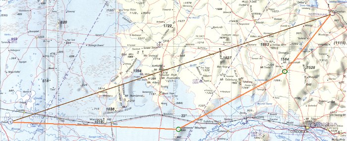 4.3.1 The four navigation techniques for flight under the visual flight rules Pilotage Pilotage is navigation by visual reference to landmarks — the art of visual track-keeping — which requires that the ground is generally continually in sight. In the early days, all air navigation was by pilotage with some crude dead reckoning. Indeed the first Pilots' Directions published by Elrey B. Jeppesen in the 1920s, for the early air mail pilots in the USA, were just notes about the landmarks along a route. As accurate aerial charts became available then aerial dead reckoning became much more refined. Map reading is the essence of pilotage. It entails: a continuous in-flight survey of the planned route (pre-plotted on the chart); identification of the upcoming chart features on the ground (i.e. reading from map to ground); and determining the actual location relative to the planned position. Following the determination of that position (and thus the actual path over the ground) dead reckoning is then used to determine the 'navigation solution': the ground speed and the track error (the angular difference between the intended route and the actual path) the subsequent course correction(s) necessary to regain and maintain the intended route a revised arrival time. Only when uncertain of your position will it be necessary to note prominent ground features and their relative positions, and then find those features on the map; i.e. reading from ground to map. Map interpretation is an acquired skill. An inability to relate the map to the ground features in view is a common experience on the initial attempts. Some find it very difficult to master. In the more remote, and rather featureless, areas of Australia what seem to be major features on the surface may not be shown on the chart, and vice versa. Dead reckoning Dead reckoning [DR] is deriving the current position, or a future position, mathematically from a planned position or the last known position. DR for light aircraft is, or should be, essentially simple navigation by clock, compass and mental arithmetic. Most of the DR for RPT and military aircraft is done within the electronic circuitry of advanced navigation systems such as inertial navigation systems [INS], which calculate a new position, from the previous position, about 100 times per second. DR has a limitation in that errors in plotting or wind velocity estimation or course steering and timing are cumulative, and the true position of the aircraft can't be verified unless it can be determined by pilotage (landmark reference) or some other position fixing technique. Supplementary technique: position-fixing Aeronautical position-fixing techniques are usually radio-based. They encompass simple techniques such as plotting the intersection of the bearings from two radio beacons, through to more complex systems such as VOR/DME which is both position-fixing and homing. Such systems usually incorporate some degree of electronic DR. The Global Navigation Satellite System [GNSS] is a continuous position-fixing or electronic pilotage system plus electronic dead reckoning to calculate the new 'heading to steer' to the next waypoint. The use of GNSS by sport and recreational VFR pilots as a supplementary navigation system is described in the 'En route navigation using the GNSS' module. The non radio-based position-fixing techniques are celestial — star sights or sun sights. Charles Lindberg's pioneering 33.5 hour 1927 New York-Paris flight was mostly dead reckoning with some star sightings, when he could see them. Supplementary technique: homing VFR homing is radio-based and encompasses non-directional radio beacon [NDB] and VHF omnirange [VOR] homing; these are described in a 'Supplementary navigation techniques' section. Note: in addition there is a module describing 'Electronic flight planning and the electronic flight bag'. 4.3.2 Creating a route Preliminary route Having decided a destination, the first step is a rough calculation to ascertain the track (the planned path over the ground), the 'distance to run' from your departure point, the approximate sector time and the viability of the proposed flight. The charts needed are a current WAC (or VNC) or adjoining WACs (or VNCs) and — if the departure point, route or destination is under the steps of a CTR — the VTC or VNC. You could also use a digitised NATMAP 250K map on a Windows desktop or laptop in the initial planning stage when you need more surface detail than that provided by a WAC. Google Earth may also be handy in locating or verifying the position of small private strips/ landing grounds. Route construction is often done the day before planned departure, or even earlier if an extensive cross-country flight is planned. With a soft pencil and a rule, draw a preliminary line on the chart between your departure and destination — you may have to overlap charts, but be aware that WAC and VNC are at different scales. Check along the line for areas to be avoided; i.e. 'tiger country' — rough, forested or hilly areas where there is a limited availability of open, cleared, flat land for an emergency landing. If possible, avoid long stretches of featureless terrain and also designated remote areas. If you are using a WAC, check the relevant ERC-L for CTR, PRD and CTAF aerodromes and mark them on the WAC. Note any other airfields near the line. Now decide which areas of terrain to avoid and find a suitable diversion around them. If that diversion takes you quite a distance from the direct line then so be it; it won't make that much difference to the total distance flown. If there are areas of scenic or other interest evident on the chart, you might plan to overfly them — even if it does makes a zigzag path. Tracking around and beneath controlled airspace If your intended track is within the area covered by a VTC you must examine the current VTC for the mandated VFR routes for aircraft flying in Class G and plan to follow those routes. They are indicated as a line of large purple dots. Carefully check the VTC and current ERSA for the altitude at which these routes should be flown. You may find, for instance, that some coastal routes require flight in one direction at 500 feet amsl and at 1000 feet for the opposite direction. The Airservices Australia Flying Guides and Publications contains a lot of information to assist in planning flights around Sydney, Melbourne, Brisbane, Canberra, Adelaide and Perth to avoid violations of controlled airspace; look for the link to 'Visual guides'. Note that on VTCs any area where the elevation does not provide at least 500 feet clearance between the terrain and the lower limit of the overlying CTA is tinted purple; such areas must be avoided. You may also find that when threading your way around CTRs, the clearance between the terrain and the overlying CTA may be so limited that all aircraft in Class G would be flying at much the same low height and tracking over the same ground, — this provides the conditions for a mid-air collision. Also in such terrain there is a significant possibility of strong lee downflows. Never plan to fly such routes unless a reasonable visibility is forecast and the winds around 3000 feet amsl are below 20 knots. The Australian Transport Safety Bureau Web site contains a research report in PDF format Limitations of the See-and-Avoid Principle, which is recommended reading. When planning to track near a CTR be aware that you must apply a tracking tolerance — offsetting it at least one nautical mile from the boundary of controlled airspace — if flight is planned below 2000 feet agl, or two nautical miles if between 2000 and 5000 feet agl; watch out for the overlaid CTA steps. A VHF radio is advisable when planning to operate close to a CTR because it is good airmanship to let them know you are there — if a heavy RPT aircraft is being let down overhead there is always a chance of being caught in sinking wake turbulence. Also if you do get caught between rising terrain and a lowering cloud base you can always call Air Traffic Control and inform them that you "require entry" to pass through the edge of the CTR because of deteriorating weather. ATC are always very helpful but unauthorised entry into the CTA or CTR (the dreaded 'violation of controlled airspace' or VCA) is a safety hazard and may earn a substantial fine. Read the article 'Lost in controlled airspace' in the online version of CASA's magazine Flight Safety Australia: November - December 2001 issue. Also see Airservices Australia's document 'Safety net: safe operations around controlled airspace'. Waypoint selection The VFR rules (ERSA ENR 1.1 para 19.2) state 'the pilot must positively fix the aircraft's position by visual reference to features shown on topographical charts at intervals not exceeding 30 minutes.' You need to find readily recognisable point locations or waypoints for monitoring flight progress and/or to mark the points of diversion and consequent turning points. Suitable waypoints are airfields with formed runways, major road junctions, small towns, grain silos near rail lines, intersecting line features and distinctive permanent water features — though in drought conditions such features may not be obvious. You may also see some highly visible linear features — roads, railways, rivers, beaches — that roughly parallel your intended track for a reasonable distance. Plan a track divergence to intercept and then follow such line features — and be aware of the 'Rules of the Road' that require aircraft to track to the right of a line feature, or when flying within a valley or any air traffic lane. In the more remote areas of Australia the distances between verifiable landmarks are great and in such cases the only viable route is to follow sealed roads. Mark all the turning points on the chart, joining them to form the route segments of the required track. These turning points will also be used as fuel consumption checkpoints. Generally speaking, a route that provides the best visual fixes and reasonably short segments is the best option. Measure the total track distance using the scale (in nautical miles) printed on the map or alternatively use the latitude graticule printed along the meridians; each mark is one minute of latitude or one nautical mile. The printed scale is easier to read and thus less prone to errors. (You can buy a ruler scaled in nautical miles for use with WACs, VNCs and VTCs online from the Airservices Australia online store navigation and planning accessories — and buy a protractor at the same time. ) Divide the total track distance by the cruise speed to get an approximate total time required. If the total time required is greater than the known maximum sector time, then the flight must be broken into two or more sectors by introducing refuelling stops at appropriate distances. This probably necessitates replanning the waypoints so that one or more coincide with an airfield with assured and suitable fuel supplies. Re-plot the route if necessary. If the total time required is less than the maximum sector time, then the first-cut plan for the route to be followed may be viable — but we have not yet taken into account the effects of wind, which may be considerable; these are covered in the next module. Forecast weather and winds should be ascertained as close to the planned departure time as possible, but it is advisable to obtain a preliminary weather forecast the evening before the flight. If a very long flight is planned it is advisable to watch the weather patterns for a few days prior to the trip. Any NOTAM applicable to the area in which you intend to operate should also be obtained at that time. See section 3.6. 'I follow roads' There is a pertinent catch-phrase amongst navigators: "Hold the heading and fly the aeroplane!". It is not possible to consistently maintain an exact compass heading in a very light aircraft at lower altitudes where the atmosphere is more turbulent, but if the variations produce a mean heading near enough to that planned there should be no difficulty. The pilot should be able to maintain the heading within ±5° or so. It is only when the aircraft is allowed to consistently wander 10° or 15 ° off course for 10 minutes at a time that planned DR navigation goes out the window and you would be better just following roads, railways or power transmission lines from landmark to landmark. In some circles that's termed IFR — not Instrument Flight Rules but 'I Follow Roads/Railways' meaning you plan to keep prominent line features in sight throughout the flight. It's a good philosophy if you are only interested in pilotage and not the challenge of dead reckoning. This purely pilotage technique doesn't preclude the requirement for proper pre-flight planning — it's just that there will tend to be a lot more heading changes than otherwise, and estimation of ground speed and re-estimation of arrival times are a bit rougher. The 'I Follow Roads' technique is different from the need to plan dead reckoning flights in remote areas of inland Australia so that they track along or near major roads — which may be the only verifiable landmarks in otherwise featureless or uniform terrain. There is a corollary in that aircraft operating under the Instrument Flight Rules must also track along designated air routes when flying from A to B, and these air routes may not be the straight line track between departure and final destination. 4.3.3 Airfield check Classification and communications Civilian airfields are classified as 'certified' [CERT] or 'registered' [REG] or 'aircraft landing area' [ALA]. Except with prearranged permission, RA-Aus registered aircraft may not enter controlled airspace (other than Class E) or a control zone. An aircraft may only enter the vicinity of, or land at, a certified or registered aerodrome if equipped with a serviceable VHF radio. The pilot, with an appropriate radio endorsement, must make the specified broadcasts and ensure that the appropriate frequency is used. Any non VHF-equipped aircraft may, with due care, land at any civilian CTAF airfield which is not certified or registered. Some aerodromes have a locally operated facility — a universal communications facility [UNICOM] usually on the CTAF (but it may be on another frequency) — which provides information on local conditions. If such a facility is operating at a CTAF airfield it is possibly unwise to enter the circuit if not VHF-equipped, as other aircraft operating in the area may not be as vigilant as they should. For more information see R/T communications and procedures in the 'VHF radiocommunications guide'. Public airfields are usually owned by a local government body and landing permission is generally not required, although it is always wise to check. Private airfields usually cannot be used without prior permission from the owner, except in an emergency — even then there may be problems with trespass. Landing and parking charges apply at many airfields. If the airfield is not shown in ERSA it will be a small private operation — possibly with a listing in the Australian Aircraft Owners and Pilots Association publication 'Airfield Directory', which has details of about 2000 airfields, including whether prior landing permission is required. If an airfield is not listed in ERSA or the AOPA Airfield Directory, then it is most unwise to contemplate using it without contacting the owner. Even if landing permission is not required, you should always pre-check with the owner/operator about hazards and conditions. It is too late to find out the surface has been softened by rain when you are up to the axles and about to flip over or find out about the wire across the landing path by striking it. Using a Google Earth image — found by the location latitude and longitude coordinates — may be a useful source of visual information for airstrips that don't appear in ERSA. Legislative requirements The regulations must also be considered when planning a landing at an unfamiliar airfield, or indeed a familiar airfield. CAR 92 'Use of aerodromes' states in part: A person must not land an aircraft on, or engage in conduct that causes an aircraft to take off from, a place that does not satisfy ... the following requirements ... is suitable for use as an aerodrome for the purposes of the landing and taking-off of aircraft ... and, having regard to all the circumstances of the proposed landing or take-off (including the prevailing weather conditions), the aircraft can land at, or take-off from, the place in safety. The civil aviation advisory publication CAAP 92-1 (1) 'Guidelines for aeroplane landing areas' expands the CAR 92 'circumstances' to be considered by ' setting out factors that may be used to determine the suitability of a place for the landing and taking-off of aeroplanes. Experience has shown that, in most cases, application of these guidelines will enable a take-off or landing to be completed safely, provided that the pilot in command: (a) has sound piloting skills; and (b) displays sound airmanship'. CASA have produced two advisory publications to support CTAF procedures and provide guidance on a code of conduct to allow greater flexibility for pilots when flying at, or in the vicinity of, non-towered aerodromes. These Civil Aviation Advisory Publications (available on this website) are: CAAP 166-1 'Operations in the vicinity of non-controlled aerodromes' and CAAP 166-2 'Pilots responsibility in collision avoidance in the vicinity of non-controlled aerodromes by 'see and avoid'. Note that the 'ultralight' term used in the CAAPs when recommending a 500 feet circuit height, refers only to those minimum aircraft which have a normal cruising speed below 55 knots, or thereabouts. CASA has produced an online interactive learning tool titled 'Operations at, or in the vicinity of, non-controlled aerodromes' which is now available at CASA online learning. Also read 'Operations at non-controlled airfields' and 'Safety during take-off and landing'. The current ERSA should be fully consulted; particularly check the circuit procedures, stated hazards and whether the airfield is certified or registered, thus requiring use of VHF radio. Hazards You must be aware of your aircraft's landing (and subsequent take-off) performance in normal, soft field and short field conditions. You must also perform a safety audit of the destination and alternate airfields for length, slope, surface condition (e.g. roughness, mud, surface water), approach and go-around hazards, stock and wildlife hazards, tyre puncture and wheel hazards, and any commonly occurring micro-meteorological and dust hazards. Check runway directions and expected wind conditions, and be wary of airfields with single runways; crosswind conditions may be beyond your aircraft's capability. Be particularly wary of airfields with 'one-way' strips — they are extremely tricky, if not outright dangerous, for those not familiar with any topographic turbulence, sink or other atmospheric hazards that could exist. Low-lying strips may be badly softened by rain or inundation. The availability and location of suitable fuel should be checked. Remember, just because your assessment concludes that you can safely land at a particular airfield it does not guarantee that you will be able to take-off safely. Note: ERSA location indicator codes. all Australian licensed, and most unlicensed, airfields are assigned a four-letter identity, where the first letter is 'Y' (e.g. Albury = YMAY). Navigation aids such as an NDB or VOR have a three-letter code (e.g. Eildon Weir VOR = ELW) and visual waypoints marked on charts have a three or four-letter code (e.g. Eldorado = ELDO). 4.3.4 Fuel planning The need for maintaining fuel reserves: In Australian general aviation and recreational aviation there is about one reported aircraft accident or incident per week that is caused by fuel exhaustion (all fuel on board consumed) or fuel starvation (mismanagement of the fuel system so that available fuel is blocked from delivery to the engine) — please ensure you are not this week's statistic. Before undertaking a cross-country flight, the pilot must know the total usable fuel capacity and the rate of consumption at the planned cruising speed. The fuel consumption rates supplied by engine/aircraft manufacturers, unless contained in a formal pilot's operating handbook, must be viewed somewhat sceptically; they may be achievable with an 'as new' engine cruising at the best endurance power setting, but are not reflective of the consumption at a more useful cruise speed, say that at 75% power. Fuel must be allowed for consumption at the departure airfield, for the climb and for circuit delays and landing at the destination or an alternate airfield. In addition, the pilot is required to plan a fixed fuel reserve. The reserve amount planned is a matter of personal discretion and the capacity of the fuel tank. It should not be less than 30 minutes in good flying conditions but a greater amount — perhaps 60 minutes — when there is any doubt about the wind velocities or other conditions.* This reserve should not be planned for use; i.e. whether the aircraft is finally landed at the planned destination or the alternate airfield there ought to be at least 30 minutes fuel in the tanks. The fixed fuel reserve concept still applies even if the planned flight is just a local flight terminating at the departure airfield — or a session of circuits and touch'n go's. *Note: The CASA civil aviation advisory publication CAAP 234-1 'Guidelines for aircraft fuel requirements' provides information and guidance on the fuel requirements for aircraft required by CAR 234. CAAP 234-1 suggests a 45 minute fixed fuel reserve for piston engine VFR aeroplanes. For recreational aircraft perhaps 45 minutes for engines of 70 hp and above and 30 minutes fixed reserve for the smaller engines (the 2-stroke and 4-stroke half-VW designs of 'low-momentum ultralight aeroplanes' tend to provide less 'time in the tank'), but read CAAP 234-1. Fuel consumption It is vital to be able to measure fuel consumption during flight, so a reasonably accurate fuel contents gauge, sight gauge or an in-flight view of the fuel tank content is necessary. It is good practice to maintain a history log in the aircraft where the actual fuel consumption per flight hour is entered at the conclusion of each flight. A consumption history log provides valuable information, both for future flight planning and for discerning engine performance trends. When planning a cross-country flight, the objectives are to arrive at the planned destination safely with a reasonable reserve of fuel in hand and without affecting the safety of others while en route; or even creating a possibility that safety might be affected. But remember the first rule of aviation — fly the aeroplane at all times, navigate when able and always be a few minutes ahead of the aeroplane. When navigating a very light aircraft, and particularly an open-cockpit ultralight, a person's capacity for mental arithmetic is not as good as it is when sitting at home. Nor is it easy — or maybe even possible in a weight-shift control aircraft — to manipulate navigation tools in flight and it is very difficult to handle charts, pencils and notepads in the cockpit. Pre-flight preparation should be directed towards reducing and simplifying the in-flight work load. You should have a good acquaintance with the flight envelope of the aircraft, both with and without a passenger. In particular you must know the optimum cruise speeds obtained when cruising at, say, 75% power plus the proven fuel consumption, in litres per hour — at that throttle setting and aircraft weight. Calculate the maximum sector time allowable by dividing the total usable fuel capacity by the hourly consumption to find hours; then deduct 30 minutes reserve fuel to arrive at the maximum advisable sector time. For example let's say our aircraft has a fuel capacity of 66 litres with 64 litres usable; proven consumption at 70 knots normal cruise is 16 litres/hour. Then maximum sector time is 64/16 = 4.0 hours or 240 minutes; less 30 minutes fuel reserve = 210 minutes. Never equate fuel consumption with distance, only time. Light aircraft consume 40% or 50% more fuel in a maximum power climb than at a normal cruise setting. It is normal practice to initially climb away at best rate of climb speed (Vy) until a safe height is reached, then airspeed is allowed to increase to a suitable en route climb speed, while maintaining maximum allowed climb power, until the cruise altitude is reached. The extra fuel consumption during the climb can be estimated from the normal rate of climb achieved. For example, rate of en route climb 250 feet/minute = four minutes per 1000 feet, then extra fuel consumed (~50%) is two minutes fuel per 1000 feet climbed. This extra fuel will be used whatever power setting is used in the climb; it is the chemical energy exchanged for the potential energy of height. There are several articles in the online version of CASA's magazine Flight Safety Australia that are recommended reading. Look under 'Fuel management' in our categorised index of the articles of particular interest to recreational pilots in Flight Safety Australia. 4.3.5 Plotting the route on a chart Reading the chart Shown below is the route we plan to fly from an airstrip on a rural property — Oxford — to an airfield at Tottenham (YTOT). Looking at the chart, the straight (dark brown) line distance is 150 nm, but there is one section of 40 nm or so, at the western end of the higher ground, that traverses a region of hills and gullies. This area may not provide suitable emergency landing sites. (A larger 141 kb plot image is available. It will open in a new browser window.) The chosen route utilises the 100 nm of low (elevation about 300 feet amsl) country, extending eastward from the departure airstrip where atmospheric conditions are likely to be less turbulent, with an east-west railway as a good line reference. There are two sentinel hills (Warraway Mountain) south of the rail line and about 75 nm east of Oxford that will provide a distinctive landmark for a turning point. The elevations shown are 895 and 987 feet, thus rising about 600 feet above the surrounding plain. All elevations on the WAC are in feet. We also note that there are two good alternate airfields in the vicinity, Lake Cargelligo and Condobolin, and find that the latter is 58 nm east of Warraway Mountain while Lake Cargelligo is 20 nm south-east of that hill (off the map image). Checking ERC-L(5) we find there is no special use airspace — restricted or danger areas — in the vicinity of our planned operation. About 50 nm north-east of Warraway Mountain and at the top of the watershed is a distinctive road junction, suitable for the second waypoint. Note the figure 1584 in bold type, just above the road junction — this indicates the highest elevation (Mt Susannah) in that WAC grid section. Similarly the figure 1528 just to the right of the junction indicates the location of the highest elevation in the neighbouring grid section. Thus we will have good indication of track holding from quite a distance if we appear to be tracking towards a position midway between those high points. Also there is a road about 20 nm north-east of Warraway Mountain, which we will cross at right angles, to provide a good ground speed check. The last segment is a 30 nm run following the valley downslope direct to Tottenham, which, from ERSA, has an elevation of 780 feet. There is a cautionary note in ERSA that a significant animal hazard (kangaroos?) exists on the airfield. Tottenham should be readily recognised from a distance by the distinctive pattern of minor roads, the rail line coming from the south-east and terminating at Tottenham, plus the mine (indicated by the crossed pick and hammer symbol) and a large grain silo. The symbol for the latter is difficult to see but it is right against the western edge of the purple circle indicating the airfield. The total distance of the three route segments is about 155 nm, very little more than the straight line route and much easier pilotage. The approximate sector time will be 155 divided by our 70 knot cruise = 2.2 hours or 132 minutes, well within our maximum sector time of 210 minutes. Thus the flight will be viable — if the weather is favourable. Checking ERC-L(5) the relevant Melbourne FIS communications frequencies are ML 124.9 for the first two legs and ML 123.9 for the final. Quantifying the route data We can now measure the non-variable route segment data to initiate the flight plan: • Centre the protractor on Oxford, ensure that the protractor is aligned with the chart meridians and read off the bearing to the first waypoint — about 094° true. • Centre the protractor on Warraway Mountain and read off the bearing to the second waypoint — about 061° true. • Centre the protractor on the road junction and read off the bearing to Tottenham — about 040° true. • Note that you can use the face of the protractor shown on the left as an erasable drawing surface. • Using a scale ruler to measure the length of each route segment we find they are 74, 52 and 33 nm respectively. Checking minimum safe altitude We now have to decide the minimum altitude at which each segment can be safely flown. We will allow a minimum safety margin of about 1000 feet above the highest terrain 10 nm either side of the required track. From the chart the highest terrain for the first segment is 1036 feet, so our lowest safe altitude is 2000 feet above mean sea level. Similarly on the second and third legs the highest terrain is 1584 feet, so our lowest safe altitude will be 2500 feet on both. The cruising altitude will be determined by the wind profile at flight time and the appropriate VFR cruising level; although for best engine performance a cruise altitude, where the throttle is fully open and the engine is delivering 65%–75% power, is indicated. The preliminary flight plan We have now accumulated the non-variable part of our flight plan: Flight plan Route segment Distance Track [true] Lowest safe altitude Comms Oxford – Warraway Mountain 74 094° 2000 ML 124.9 Warraway – road junction 52 061° 2500 ML 124.9 Road junction – Tottenham 33 040° 2500 ML 123.9 Before we can proceed further we must: ascertain the weather and the wind velocities that are forecast for the period of our planned flight check for NOTAM that may affect us determine the times of first light / last light, remembering that VFR pilots should not plan to be airborne before first light plus 10 minutes nor after last light minus 10 minutes if the air temperatures are above average and/or the departure, destination and alternative airfields are elevated, calculate the density altitudes and decide whether all possible take-offs and landings can be conducted safely. First light/last light; the official times for 'first' and 'last' light are purely a mathematical calculation and do not take into account diminution of light caused by terrain shadowing, cloud overcast, haze or mist. In southern Australian winter conditions it may be advisable that lengthy VFR flights should be planned to conclude at least one hour before the official last light. 4.3.6 Obtaining weather forecasts, NOTAM, first light and last light Aeronautical briefing information — the NAIPS Internet Service Airservices Australia provides an online forecast service for 30 or so aviation forecast areas — ARFORs — shown on the PCA. First we need to locate our flight area on the PCA — outlined in green on the PCA section shown and thus located in ARFOR 22. The black grid on the PCA is the individual WAC coverage so our planned flight area (outlined in green) is more or less contained in WAC 3457 but we would certainly need to also take along WAC 3356 adjoining the northern edge of WAC 3457. Weather forecasts, NOTAMs and other pre-flight information are downloadable from Airservices Australia's [AsA] NAIPS Internet Service [NIS], 'a multi-function, computerised, aeronautical information system. It processes and stores meteorological and NOTAM information as well as enabling the provision of briefing products and services to pilots and the Australian Air Traffic Control platform'. NIS is accessed through the internet with any web browser or access may be integrated within flight planning software. The Bureau of Meteorology provides all the weather products to the NIS. The old AIS/MET service is, or will be, discontinued. You must register with AsA before you can access the NIS. You are required to create a 'user name' and a password. If you don't have an ARN or Pilot Licence Number leave that field blank, don't use your RA-Aus or other sport and recreational organisation membership number, it may conflict with someone's Aviation Reference Number. Download the NIS user documentation When registered, you can log in; enter user name and password, and then click the required link. If you choose 'Area Briefing' you can select up to 5 briefing areas by clicking on the map or by entering the required areas or sub areas (4-digit codes) in the entry boxes, place a check in the 'Head Office Notam — summary' request box, enter the validity period and then click on the 'Submit' button. Alternatively, click on the Area Directory link to select any of the area or sub areas from the the directory list. An area briefing provides area meteorological information, NOTAM and meteorological information on aerodromes, NOTAM for restricted areas within the selected area, and relevant Flight Information Region meteorological and NOTAM information. The aerodrome meteorological information is in the form of Meteorological Reports [METAR] and Aerodrome Forecasts [TAF]. We will look at the meteorological information in the flight plan preparation module for which I have downloaded an area 22 ARFOR and added some comments (this opens in a new browser window). Plain English conversions of current ARFOR, METAR and TAF for all Australian ARFOR areas are available from Ian Boag's website. However pilots must still get the NOTAM from the Airservices site. Also student pilots should be aware that the ability to decode the BOM information will be tested in some of the aviation examinations. Bear in mind that CAR 120 imposes penalties for use of forecasts that were not made with the authority of the Director of Meteorology or by a person approved for the purpose by CASA and it may be that plain English conversions are not authorised by the Director or CASA. The times of first light and last light for any Australian location are accessed from the opening page — click 'First Light-Last Light'. Current UTC date and time may be derived with the 'Time Zone Converter (Local To UTC)'. Bureau of Meteorology aviation weather services You can also download the current and forecast national weather charts (plus a great deal of other information) from the Australian Bureau of Meteorology website aviation weather services page. The colour images from the BoM's Weather Watch Radar Network indicate the intensity of atmospheric precipitation overlaid on a surface map for an area up to 512 km radius from the radar. The radar images are updated every 10 minutes or so and the latest four images can be rolled into a progressive display that gives an indication of the development and velocity of such weather phenomena. The weather radars provide the most accurate and up-to-date rain and storm information, and should always be checked prior to a flight within areas covered by the radars. Lightning trackers such as Weatherzone provide useful information on current storm location and movement. 4.3.7 Educational material available from the Civil Aviation Safety Authority website Several eLearning tutorials are accessible from the 'Online learning' page in the Education section. Each tutorial topic takes 5–10 minutes to complete and the whole tutorial can be completed at your own pace. Fuel management Class D Airspace Procedures Operations at, or in the vicinity of, non-towered aerodromes OnTrack is a series (currently 12) of online, interactive guides to VFR operations in and around controlled airspace associated with six Class D general aviation aerodromes plus six Class C CTRs. They are accessible from the 'OnTrack' page in the Education section. OnTrack features interactive maps with added visual terminal chart (VTC) information utilising video, audio, pop-up alerts and text. OnTrack is not of much interest to most RA-Aus pilots because, unlike the Visual Pilot Guides, the Class C and Class D bypass routes don't seem to be included (yet?). Five Visual Pilot Guides are accessible from the 'Visual Pilot Guides' page in the Pilot guides & information section, the last revision was 13 December 2010. These publications are pdf format guides to VFR operations near Australia's major cities. The main purpose is to facilitate route planning into or from the Class D general aviation aerodromes — which is not of much interest to most RA-Aus pilots. However the guides also help familiarise recreational aviators with the recommended VFR routes, altitudes and VHF frequencies that provide safe navigation around and under the Class C and Class D airspace steps, military control zones and restricted areas. Melbourne Basin Visual Pilot Guide 11.3 MB Sydney Basin Visual Pilot Guide 10.9 MB Jandakot Visual Pilot Guide 4.8 MB Archerfield Visual Pilot Guide 4.5 MB Parafield Visual Pilot Guide 3.9 MB CASA's Visual Flight Rules Guide (November 2011 version) is now only available in pdf format, downloadable in six sections and accessible from the Pilot guides & information section. General: the rules, licensing, pilot responsibilities, radio procedures 5 MB Pre-flight planning: meteorology, briefing, notification, information services 6 MB Operations: communications, non-controlled aerodromes, controlled airspace, sport aviation 8 MB Helicopter operations 3 MB Emergency procedures 3 MB Index 2 MB Safety-related videos may be viewed at the CASABriefing YouTube channel. Stuff you don't need to know • DR was born in the early days of oceanic sailing vessels. Every hour or two during the voyage the log (a quadrant shaped piece of wood weighted to float upright with an attached log-line knotted at intervals) was dropped over the stern of a vessel under way and the vessel's speed was reckoned from the amount of line paid out over a particular period of time. In 1637 an English mathematician and navigator, Richard Norwood, calculated that the spacing between knots should be 47.25 feet with a 28 second sand glass used as the timer. If you do the calculation, using the then estimated 6075 feet to the nautical mile, you will see that the number of knots that passed over the stern rail during the 28 second period equals the ship's speed in nautical miles per hour — hence knots. The log was presumed to be 'dead in the water'; i.e not dragged by the ship or affected by tide, drift or current. Each reading was marked on a log-slate and, during each watch, the course, speed and distance reckonings — adjusted for tide and current estimates — were entered in the logbook. (Note: some obviously non-nautical people reckon that 'dead reckoning' is a diminutive of 'deduced' reckoning, but I reckon their reckoning is wrong. According to the Oxford English Dictionary the term 'dead reckoning' first appeared in print in 1613 in a work titled 'Magnetic Bodies' written by one M. Ridley; so the term has been in use for at least four centuries. The term also appeared in Richard Norwood's work, The Seaman's Practice, published in 1637.) STRICT COPYRIGHT JOHN BRANDON AND RECREATIONAL FLYING (.com)
 -
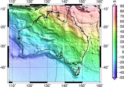 4.2.1 Defining position – latitude, longitude, altitude and time Lateral dimensions In aerial navigation any point on the Earth's surface may be precisely defined in terms of a latitude and longitude graticule reference. Meridians of longitude are half 'great circles', perpendicular to the equator, that extend from pole to pole. The meridians are identified by the angle that they subtend, at the centre of the Earth, with the prime meridian. That angle is measured in degrees, minutes and seconds east or west from the prime meridian: the WGS84 International Reference Meridian — or 0° longitude or prime meridian — passes about 102 metres east of the originally defined Greenwich meridian at the Greenwich Observatory, England subsequent meridians are identified as degrees east or west around to 180° there are 60 minutes of arc in a degree and 60 seconds of arc in a minute. Parallels of latitude are 'small circles' drawn around the Earth starting from the equatorial plane, north and south of the equator and parallel with it and reducing in circumference toward the poles. For our purposes we can say that the parallels appearing on aviation charts are identified by the angle that they subtend with the equatorial plane, i.e. they are geodetic, measured in degrees, minutes and seconds and whether they lie north or south of the equator: the north pole is a point position having a latitude of 90°N the south pole is a point position having a latitude of 90°S the equator has a latitude of 0° and is a great circle, in that it is formed by a plane that passes through the Earth's centre, bisecting the Earth's sphere. One nautical mile is the length, at the Earth's mean sea level surface, of one minute of arc of a great circle. The International Nautical Mile is 1852 metres or 6076.1 feet. Consequently, one degree of latitude (measured along a meridian) has an equivalent surface distance of 60 nautical miles, and one second of latitude is about 31 metres, while 1/100th of a second is about 0.3 metres. Seconds of arc are generally not used in those aeronautical publications intended for navigation under the Visual Flight Rules; latitude and longitude is expressed in degrees plus minutes to (generally) one decimal place — about 185 metres. For example the reference point for Mount Beauty airstrip in Victoria is located at S36° 44.1' E147° 10.2'; aerodrome reference points (usually regarded as the centre of the airfield) are defined in degrees, minutes and tenths of minutes. However, when necessary, the location of a point position may be specified much more precisely; some point locations for instrument landings are required to be specified to 1/100th of a second. Some systems may use degrees only, in which case the degrees may be expressed to five decimal places, e.g. S36.73499 Incidentally, a 'knot' is a speed of one nautical mile per hour. It is logical to express 'Lat/long' coordinates with the direction from the equator/prime meridian first (e.g. S and E), then a numeral group representing the degrees followed by a group for the minutes. The symbols for degrees and minutes are omitted, e.g. S36 44.1 E147 10.2. That is the standard format for geographic locations in ERSA. However in the global navigation satellite system (GNSS), and other systems, the northern hemisphere latitude coordinates may be represented as a positive value and the southern hemisphere as a negative value, while the longitude coordinates for the western hemisphere have a negative value and those for the eastern hemisphere have a positive value, so S36 44.1 E147 10.2 is represented as −36 44.1 +147 10.2. The positive sign is usually omitted for the northerly and easterly coordinates. Effect of continental drift on precise location The Earth's latitude/longitude reference graticule is regarded as fixed relative to the Earth as a whole, but the continents are in motion. The Australian tectonic plate, for example, is moving north north-east towards the North Pacific at the rate of seven centimetres per annum*. So, during the last 14 years every fence post in Australia has moved one metre north north-east and their precise latitude and longitude reference position has changed, and will continue to change. Of course these tectonic plate movements have no discernible effect on aerial navigation but they do complicate land survey activities. In Australia, to overcome this the 1994 Geocentric Datum of Australia [GDA94] uses a reference meridian that is fixed relative to the Australian tectonic plate rather than the International Reference Meridian. The map projection for GDA94 is the Map Grid of Australia [MGA94]. *For comparison, it is estimated that the average fingernail growth is 3.5 cm per annum. The third positional dimension – altitude Contour lines and spot points on topographical maps provide an indication of terrain elevation — i.e. height above the Australian Height Datum. The aircraft's altimeter reading provides the aircraft's vertical position and thus the current height above the terrain indicated on the chart — height above ground level [AGL] or the terrain clearance — may be determined. Universal Coordinated Time Time is a most important dimension in aerial navigation; the reference time is Universal Coordinated Time (symbol UTC — a compromise between the initialisms of the preferred French and English names) rather than local times. UTC is the time at the International Reference Meridian and is an average of a large number of atomic clocks. The suffix 'Z' is used to identify dates and times as UTC, so it may be referred to as 'Zulu' time — the phonetic for 'Z'. UTC and the 24-hour clock system — rather than local time — are used throughout the aviation information, communication and meteorological services. UTC is 10 hours behind Australian Eastern Standard Time, 9.5 hours behind Australian Central Standard Time and 8 hours behind Australian Western Standard Time. Add an additional hour in a daylight saving time period. 4.2.2 Defining the shape of the Earth – geoids and ellipsoids The Australian chart elevation reference datum — the Australian height datum The Australian height datum* [AHD] is based on the average local sea level as observed throughout 1966-1968 at each of 30 tidal gauges distributed around the coastline and is the zero elevation reference for Australian aeronautical charts; i.e. the elevations shown on the charts are height above the AHD or mean sea level [msl]. * A datum is the fixed reference or starting point of a scale or measurement system e.g. an aircraft weight and balance pre-flight check. In this context the plural is datums not data. The Australian geoid The Earth's density is not uniform throughout, thus gravity and its perpendicularity — and consequently msl (or AHD) distance from the geometric centre of the Earth — varies irregularly around the surface of the globe. A geoid is a notional surface of equal potential gravity within the Earth's gravity field, that describes that irregular shape and basically follows mean sea level over the oceans and extends through the continents. The current Australian geoid is AUSGeoid09 but for aerial navigation it can be regarded as equivalent to the Australian Height Datum ±0.5 m. Check Geoscience Australia for more information about geodetic datums. The World Geodetic System 1984 A geoid is not the same as an ellipsoid (a smooth, slightly flattened sphere), which is a mathematically (rather than physically) derived representation of the Earth's underlying shape. The WGS84 ellipsoid is a mathematical representation of the Earth's underlying shape with an equatorial radius of 6 378 137.0 metres, a polar axis radius of 6 356 752.314 metres and a flattening ratio of roughly 1:300. There are many ellipsoids in use but WGS84 is of most interest to Australian aviators because it is the reference ellipsoid used by the Global Positioning System and is its basis for GPS altitude, whereas the Australian Height Datum (a 'geoid') is the basis for elevations on Australian navigation charts. GLONASS uses other ellipsoids. For aerial navigation and cartography purposes the shape of the Earth is defined by the WGS84 ellipsoid providing the standard coordinate frame for navigation/cartography systems. Some Australian charts may also show the GDA94 as the datum, which is fixed relative to the Australian tectonic plate as mentioned above, however for navigation purposes, this is compatible with WGS84. Geoid-ellipsoid separation and GPS altitude The difference in elevation of a particular point on the Earth's surface — when measured against both the ellipsoid and the geoid — can be quite considerable, as much as ±100m ; this is known as the geoid-ellipsoid separation. In Australia the degree of geoid-ellipsoid separation is quite unusual. The image below shows the substantial geoid undulation that slopes across Australia. In the south-west corner of the continent AUSGeoid09 is 33m below the WGS84 ellipsoid while at the tip of Cape York in the north-east corner it is 72m above the ellipsoid. As shown in the image the geoid and ellipsoid coincide (i.e. zero separation) on a rough line between Port Hedland and Melbourne. (Image courtesy of Geoscience Australia). The local value (known as the 'N-value') of the geoid-ellipsoid separation might be shown on aeronautical navigation charts but the values are not shown on Australian charts. The local N-value is of little significance to recreational aviators (although it should be noted that a GPS instrument may give an apparently incorrect height if the software doesn't adjust for the local N-value*) but may be of great significance to IFR pilots and designers of GPS approaches when the GNSS achieves sole-means navigation status for all flight phases. A table of the geoid-ellipsoid separation value for each cell of a roughly one nautical mile square grid covering Australia is produced by Geoscience Australia's National Geographic Information Group — previously known as AUSLIG. AUSGeoid09 provides the AHD-to-ellipsoid separations, see the AustGeoid09 on the Geoscience Australia site. *Note: some GPS receivers may store just a single N-value for each 10° latitude/longitude graticule cell. As can be seen from the image above some 10 x 10 degree cells have a 40-50m variation diagonally across the cell. If the N-value is not used or just approximated, the calculated GPS altitude may be incorrect. 4.2.3 Aeronautical charts Chart system basics A chart system is built on three basics that must be defined for use: the projection employed — generally the 'Lambert conformal conic projection' for air navigation. the coordinate system — latitude and longitude for air navigation. the geodetic datum — WGS84 [or GDA94] is the standard horizontal (area) datum for most Australian aeronautical charts and the Australian Height Datum is the vertical datum. Note: when using a GPS receiver ensure that these three formats have been selected correctly, particularly the WGS84 datum. A map intended for aerial or marine navigation is usually referred to as a 'chart'. The chart graticule is latitude and longitude, with the meridians more or less vertical on the sheet but converging slightly. As the Earth is ellipsoid, there has to be a technique to map the image of the surface of the three-dimensional ellipsoid onto a flat two-dimensional chart without overly distorting the represented areas. The most suitable projection technique for world aeronautical charts is the 'Lambert conformal conic projection'. Although this projection distorts areas a little, distances anywhere on the chart have the same scale. The great circle arc* — the shortest distance between two points on the surface of a sphere — can be represented reasonably accurately by the flight planner drawing a straight line between two points on the chart. However you will note that the angle at which that straight line crosses each meridian changes because of the convergence of the meridians. *Note: the shortest distance between, say, Sydney and Perth, is a straight line (a tunnel) joining those cities and passing through the Earth. The great circle route follows that 'tunnel' on the surface. The Lambert chart legend will indicate the latitudes of two 'standard parallels'. There is no scale distortion at these parallels, however scale distortion increases with distance from a standard parallel. For an explanation of standard parallels see www.icsm.gov.au/mapping/about_projections.html and look for the heading 'Multiple standard parallels or central meridians'. Those meridians of longitude shown on Lambert conformal aeronautical charts are straight lines, that converge towards the poles*. On a southern hemisphere chart the meridian spacing between the meridian lines at the bottom of the sheet is a little less than that at the top — about 5 mm on an Australian 1:1 000 000 World Aeronautical Chart. A central meridian drawn on each chart is vertical and the others converge towards it. The parallels of latitude as shown on the chart are arcs of circles and cross all the meridians at right angles because of the slant of the meridians. If a straight line is drawn diagonally across the chart, the angle that this great circle route subtends with each meridian varies slightly across the chart. Aircraft flying very long legs would alter their heading slightly every 500 nm or so to maintain the great circle route and thus the shortest distance. *Note: that convergence of the meridians is why the 'grid' on such charts is called a 'graticule'; the meridians and parallels do not form true rectangles, i.e. a 'grid'. If you joined a number of WACs together by matching parallels and the edge meridians the maps would form an arc. On Mercator (a 16th century Flemish geographer) cylindrical projection charts, straight line plots are 'rhumb lines' and great circle plots are curved. A rhumb line is a line drawn so that it crosses the meridians of the Mercator projection at a constant angle, but it is not the shortest distance between two points; an aircraft flying a constant track heading would be following a rhumb line plot. The concept of choice between a great circle route or rhumb line route is interesting but inconsequential to a light aircraft navigator because a constant track heading (i.e. a rhumb line track) is usually flown for each leg; except, perhaps, if planning a direct route from Australia to New Zealand. The scales used for aeronautical charts are the representative fractions 1:1 000 000, 1:500 000 and 1:250 000. The latter scale means that an actual distance of 2.5 km (250 000 centimetres) is represented by one centimetre on the chart. The 1:1 000 000 scale is a small-scale chart; i.e. it covers a large area but with minimum detail, one centimetre represents 10 km. The 1:500 000 and 1:250 000 are larger-scale charts that cover progressively smaller areas but with increasing detail. The Australian Intergovernmental Committee on Surveying and Mapping's Fundamentals of Mapping is well worth visiting. Recommended VFR charts The paper charts recommended for sport and recreational aviation VFR flight planning, in-flight navigation and sourcing VHF radiocommunications data are: Planning Chart Australia: the PCA is a single sheet showing the coverage of the WACs (below), the meteorological area forecast [ARFOR] boundaries, the estimated FIS VHF coverage from both 5000 feet amsl and 10 000 feet (but not the frequencies), and the areas without FIS VHF coverage. The FIS HF communication frequencies are shown. The spot location of about 700 named airfields is indicated. PCA is designed to assist in initial VFR flight planning and it is amended semi-annually. It is of rather limited use in initial planning of flights below 5000 feet (i.e. most ultralight flights) in eastern Australia because straight-line tracks between departure point and destination may be precluded because of the topography, and there are no indications of such on the PCA. But it is generally okay for use west of the Dividing Range. Also it is the only chart that indicates FIS VHF coverage; essential knowledge if a flight is being planned into the less accessible areas of Australia. World Aeronautical Charts: the 43 Australian WACs are small scale (1:1 000 000 or 1mm=1km), derived from aerial photography, and designed for pre-flight planning and pilotage. They are part of an ICAO international series. They do not indicate CTR or PRD, nor is there any FIA, radiocommunications or radionavigation information. As the reissue frequency is 2–4 years (i.e. 50% of the 43 maps are supposed to be re-issued every two years) the base can be slightly out of date, particularly in regard to the infrastructure. Amendment lists for each edition are published in AIP SUP but these amendments generally relate to location of airstrips and special activities rather than topography or infrastructure. Each WAC generally covers 6° of longitude and 4° of latitude. Sheet dimensions are about 70 × 60 cm and the scale is such that a real distance of one nautical mile is represented by less than 2 mm on the chart; thus WACs are really not suited to low-altitude navigation in slow aircraft, but it is wise to always have the latest edition of the WAC/WACs — relevant to the journey — in the cockpit. Visual Navigation Charts: the VNCs are a larger scale at 1:500 000 and show airspace information and FIS detail laid over the topographic base. All VNCs are reissued at six-monthly intervals but the base topographic detail may not be up to date. They are far superior to the WACs for both flight planning and pilotage. VNC sheet dimensions are about 100 × 60 cm and contain the following airspace detail: CTR, CTA dimensions and lower levels Flight Information Area and Surveillance Information Service boundaries where available Flight Information Service and Surveillance Information Service frequencies and providers communication and navigation aid frequencies for licensed airfields PRD and designated & remote areas. There are only 15 VNCs, those available covering the more populous areas of Australia — Tasmania to North Queensland, plus areas around Perth, Adelaide, Darwin and Tindal. Visual Terminal Charts: the 25 or so VTCs provide both aeronautical and topographic information around major airports at a scale of 1:250 000. They are essential for VFR operations in the vicinity of such airports to avoid violating controlled airspace. In some cases, these charts show the details of tracks to be flown and significant landmarks to be used by pilots of VFR aircraft to avoid inadvertent entry into controlled airspace. All VTCs are amended and reissued every 6 months. The charts are based on the NATMAP 250K series maps and use the Universal Transverse Mercator [UTM] projection but with a latitude/longitude graticule rather than the normal UTM grid; their dimensions are around 90 × 50 cm and show the following details: PRD areas CTR and associated CTA dimensions including the lower levels of the CTA steps surrounding the airport, lanes of entry, ATC check points Surveillance Information Service frequencies where available communication and navigation aid frequencies for licensed airfields VFR approach points. En Route Chart (low level): the ERC-L series is drawn to various scales to accommodate significant air traffic route areas and shows controlled airspace, PRD areas, air routes and segment distances, ATS and radio-navigation services, ATS frequencies and location, plus communication and navigation aid frequencies for licensed airfields — but no topography. It also indicates those airfields where VHF radio contact with FIS is possible from the ground. The FIS area boundaries are shown together with an information box showing the provider of the flight information service (e.g. Brisbane Centre), the frequency and the location of the area transceiver. The series of eight sheets cover Australia and are intended primarily for IFR flights conducted below 20 000 feet. The multitude of air routes that radiate from major cities make the charts difficult to read but they are the only chart series that show all the FIS frequencies, PRD areas and give indications of sports aviation activities — thus they are an essential document for VFR navigation. Each route segment is a great circle route with the magnetic track angles measured at the end points rather than the middle of the segment, which is why there is an apparent discrepancy in the reciprocal track angles. Reissue frequency is twice per year. PCA, WAC, VNC, VTC and ERC-L can be purchased from the Airservices Australia online store. You can see the coverage for each sheet in each series by clicking 'Coverage Map' on their 'Aviation charts' page. These charts can also be ordered from pilot supply shops. Possibly the TPCs may be purchased from the National Mapping Division of Geoscience Australia. Satellite and aerial images of the Earth's surface are also available via the Google Earth and Google Map geobrowsers and provide help in flight planning; for example, the ability to locate an unlisted airstrip and establish the exact lat/long coordinates for entry into a GPS. Carriage of flight documentation AIP ENR 1.10 para 5.1 states: 'Pilots are required to carry, and have readily accessible in the aircraft, the latest editions of the aeronautical maps, charts and other aeronautical information and instructions, published: a. in AIP, or b. by an organisation approved by CASA, that are applicable to the route to be flown, and any alternative route that may be flown, on that flight.' (The AIP entry is an extract from CAR 233 'Responsibility of pilot in command before flight') Digitised aeronautical charts The WAC, VNC, VTC and ERC-L charts, and others for flight under the instrument flight rules [IFR] , are also available in digitised format — raster or vector images — for use in tablet computers with flight planning software and for inflight use with portable electronic devices with moving map software. They have the same reissue frequency as the paper charts. This is discussed in the 'Electronic planning and electronic flight bag' module. 4.2.4 Map topography Aircraft operating under the VFR must navigate by visual reference to the ground. The lower the level at which a flight is planned, the more important it is that the pilot is able to visualise a three-dimensional image of the terrain from the graphical details presented by the two-dimensional topographic chart — by the usage of colour, symbols and lettering. To assist this visualisation, WACs and VNCs display tinted topographic contours signifying surface areas between the 660 feet (200 m) and 1639 feet elevations, 1640+ feet (500 m), 3280+ feet (1000 m), 4920+ feet (1500 m) and 6560+ feet (2000 m) levels. The shape of the contours and the width between them indicates the form of the land and the gradient. The closer the contour lines (i.e. the narrower the colour bands) are to each other, the steeper the gradient. Also the WAC utilises relief shading of elevated ranges and ridges so that they are more evident. In addition, spot elevations are shown and the highest spot elevation within each chart graticule is recorded in a bolder lettering than other spot elevations. The graticule on the WACs and VNCs is spaced at 30 minutes of latitude and 30 minutes of longitude: 30 nm in latitude and, for much of Australia, around 24 nm in longitude. The contours on VTCs are at 500+, 1000+, 2000+, 3000+, 4000+ and 5000+ feet amsl, but in addition all areas are shaded purple where there is less than 500 feet of clearance between the terrain and the lower limit of the overlying controlled airspace. Like WAC and VNC, the highest spot elevation within each chart graticule is shown in a bolder type than other spot elevations. The graticule is spaced at 10 minutes of latitude and 10 minutes of longitude: 10 nm in latitude and around 8 nm in longitude. The VTCs generally cover an area within a 40–50 nm radius from the major airport and are the essential chart for visual navigation within that area. Vegetation is usually not shown on WACs, nor are many structures except for towers and similar obstructions to low-flying aircraft; although grain silos — which are an excellent navigation aid usually associated with a railroad — are shown. Railroads, power transmission lines and some roads are depicted. 4.2.5 Defining direction — the aircraft direct reading magnetic compass Sport and recreational navigation under the VFR is basically azimuth and distance and is also short-range i.e. each leg is usually less than 500 nm or so. Directions in azimuth are usually expressed as the angular distance from the north pole — true north — in whole degrees from 0° at north clockwise to 360°; i.e. north is both 0° and 360° (though is usually expressed as 360°). For example, the direction due east from any particular location is 090°. These directions may be described as bearings, headings, courses or tracks depending on the application. Direction is usually paired with distance expressed in nautical miles, thus the bearing and distance of a location 55 nm due east would be expressed as bearing 090°/55. However, the prime navigational direction instrument — the magnetic compass — aligns itself with the north magnetic pole and, in Australia, the variation between the direction to true north and that to magnetic north can be as much as 13 , so there is a need to define directions in terms of 'degrees true" or 'degrees magnetic'. Civil Aviation Order 20-18 specifies just four mandatory flight and navigational instruments for flights under the day Visual Flight Rules. These basic instruments are: an airspeed indicating system an altimeter, with a readily adjustable pressure datum setting scale graduated in millibars an accurate timepiece indicating the time in hours, minutes and seconds, which may be carried on the person of the pilot and a direct reading magnetic compass. If the aircraft is a Light Sport Aircraft for which a current special certificate of airworthiness or an experimental certificate has been issued it need not carry the individual instruments as defined above, if equipment is carried that provides a pilot with the same information, i.e. an electronic flight display. Magnetic variation The simple direct reading compass is essentially a bar magnet freely suspended in a lubricating fluid designed to damp out oscillations, vibrations and swings caused by aircraft accelerations. The bar magnet, which may be a needle or part of a circular compass card, aligns itself with the Earth's local magnetic lines of force with the north-seeking end pointing roughly north. The Earth's magnetic field is systematically surveyed so that the difference between the direction at which a compass points — magnetic north— and the direction of true north is measured. That difference is called variation, or declination if you are of a scientific bent, and is expressed in degrees of arc east or west of true north. The magnetic lines of force at any location may also be substantially varied by local magnetic anomalies — substantial iron ore deposits for example. Lines on a chart joining locations with equal magnetic variation are isogonals, or isogonic lines, and are shown on WACs and VNCs as dashed purple lines at half-degree intervals. The local variation may also be shown numerically on some charts. The isogonals on Australian charts vary from 3° west in the south-west corner of the continent to 13° east on the eastern coast. This means that if you want to fly from A to B, the direction ascertained from the chart will be relative to true north — the true course — and let's say it is due west, 270°. If you then set 270° on the aircraft compass and fly that heading then your track over the ground will not be due west but will vary according to the variation. Let's say the variation is 10° east then the true course you are flying will be 280°. This small complication requires that when you have finally calculated the true course you have to fly to get from A to B, after allowing for the effects of wind, then you need to convert it to a magnetic heading. The conversion rule used for at least the past 70 years is: "Variation east, magnetic heading least; variation west, magnetic heading best". So if the local variation is 12° east the magnetic heading will be the true course minus 12°; e.g. true course 010°, magnetic heading 358°. If the variation is 2° west the magnetic heading will be the true course plus 2°; e.g. true course 010°, magnetic heading 12°. For all wind velocities, given in meteorological forecasts and actuals, the directions are relative to true north, except if you happen to hear a broadcast from a CTR tower controller (or an Automatic Terminal Information System [ATIS] broadcast) who provides the wind direction as magnetic, because the airfield runway numbers are relative to magnetic north. The air route directions shown on ERC-L are also relative to magnetic north. Compass deviation Aircraft compasses are also deflected by magnetic fields within the aircraft, some related to ferrous engine/structural metals, others related to electrical currents. These aircraft magnetic fields produce heading errors — compass deviation — which vary according to the aircraft course, either reducing or increasing the Earth's magnetic field. These errors can be quite significant, 30° or more, and any magnetic field within about one metre of the compass may have a discernible effect. Mobile telephones in the cockpit may also affect the compass. Compass error is the combination of variation and deviation adjustment necessary to determine the compass heading that will provide the true course. A bar magnet aircraft compass will have screw-adjustable compensating magnets to negate or at least reduce the effect of these magnetic fields. The compass and aircraft must be 'swung' to make these adjustments, and the residual deviation errors noted on a compass correction card displayed in the cockpit. Residual deviation errors should not exceed 10° at any compass point. The procedure for 'swinging the compass' is time-consuming and difficult but necessary. We will go further into compass deviation in the 'En route adjustments' module. Airfield runway numbers are stated as their magnetic heading rounded off to the (supposedly) nearest 10°; thus an east-west runway will be numbered 09/27. The ERSA entry in the "Physical characteristics" section for the airfield usually shows the actual magnetic heading following the runway numbers, but only for one direction. For example at Dubbo aerodrome '05/23 043' indicates the actual magnetic heading for runway 05 is 043° magnetic, and consequently 223° for runway 23. Thus, when stationary and accurately lined up for take-off on such a runway, you can measure deviation on that heading; but make sure the compass has stopped moving. Flying to a few airfields and checking deviation at various runway headings is one way of producing a compass correction card. Always make sure the compass fluid level is okay. A vacuum chamber for de-aerating the compass fluid must be used in the re-filling process — using the proper fluid, not alcohol. Bar magnet compasses are also affected by vibrations, aircraft accelerations and inertia when turning; thus they tend to be shifting constantly. Compass acceleration errors are most apparent when the aircraft is on an east/west heading and least apparent when on a north/south heading. The turning errors require the pilot to make an undershoot/overshoot adjustment when changing heading. To overcome these errors, normally the magnetic compass is accompanied by a gyroscopic instrument that indicates the direction in which the aircraft is heading, without being subject to external forces. This electrically or suction-operated directional gyro [DG] or direction indicator [DI] is initially aligned with the compass before take-off and needs to be realigned occasionally during flight; however, few ultralights are equipped with DGs. Electronic flight information systems [EFIS or 'glass cockpits'] are now becoming much cheaper and thus a reasonable proposition for amateur-built light aircraft. These systems use solid-state electronic componentry plus software to present a cockpit display incorporating the functions of most single flight instruments. In such systems magnetic field strength sensors (magnetometers) are used to provide a three-dimensional magnetic compass that displays magnetic heading without acceleration, attitude or turning errors; thus it also incorporates the DG facility. The simple direct reading magnetic compass must still be part of the aircraft equipment. Things that are handy to know • There are other maps such as the Australian NATMAP 250K series. This is intended mainly for surface use, with the GDA 94 datum and using the Map Grid of Australia projection (MGA 94) which conforms with the Universal Transverse Mercator (UTM) projection with usually the metric UTM Eastings and Northings grid — rather than a latitude/longitude graticule. This coordinate system is more complex than latitude/longitude — the Earth's surface is divided longitudinally into 60 six-degree numbered zones and Eastings are measured in metres (to 3 decimal places) from the central meridian of each zone. Northings start from zero at the equator in the northern hemisphere but, for the southern hemisphere, start from a 10 000 000m base Northing at the equator. See en.wikipedia.org/wiki/UTM_coordinate_system. Fortunately the digitised NATMAP 250K series are also available with a latitude/longitude graticule, so these larger-scale (1:250 000) maps could be used for the limited leg distance of recreational aircraft navigation, particularly with GPS. Each map covers an area of 1.5° longitude and 1° latitude. VTCs, being based on the NATMAP 250K, use the Transverse Mercator projection with a lat/long graticule. Some UTM maps may show the lat/long graticule* in one colour with the UTM grid* in another. *Note: 'grids' are rectangular in shape; the 'graticule' is not — the meridian lines converge poleward. The digitised NATMAP 250K series may be purchased from Geoscience Australia. The 513 maps of the NATMAP 250K series are available on DVD for about $100 which is less than 3% of the cost of the paper series and well worth having as home reference material — even if you don't use them for aeronautical navigation. They are in ECW format and software is supplied for viewing and for export to geoTIFF, TIFF, JPEG, PNG, bitmap or OziExplorer format. Image resolution is 200 dpi and the pixel size is around 30 metres with a positional accuracy of 127 metres. The 'Map Viewer' software supplied is currently (2012) confined to Windows operating systems. View 'About NATMAP Digital Maps 2008'. Stuff you don't need to know • Maps that lack contours, like street maps, are planimetric; i.e. flat. • 'Large scale' maps are those with a scale of 1:70 000 or less. STRICT COPYRIGHT JOHN BRANDON AND RECREATIONAL FLYING (.com)
 -
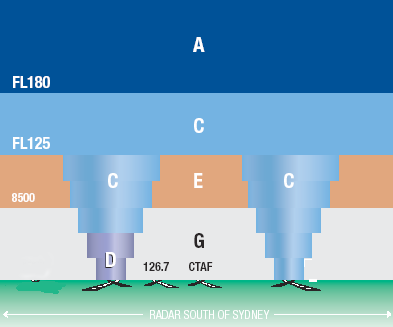 4.1.1 Controlled airspace 'Controlled airspace' is airspace of defined dimensions within which air traffic control service is provided in accordance with the airspace classification. There are two types of controlled airspace: A Control Area [CTA] is controlled airspace that extends from a specified limit above the surface (e.g. 8500 feet amsl) to some upper level (e.g. 18 000 feet amsl — or FL180). A Control Zone [CTR] is controlled airspace, surrounding a civil or military aerodrome (with a manned Air Traffic Control tower), that extends from ground level and is stepped up to the lower limit of the overlying CTA. The steps provide the airspace for the airport approach and departure paths. Please note: the CTA abbreviation is commonly used when referring to the generic controlled airspace (i.e. CTA plus CTR) rather than just Control Area(s). There is no abbreviation listed in the Australian Aeronautical Information Publication [AIP] for the generic 'controlled airspace'. OCTA is the AIP abbreviation for the term 'outside control area' and OCTR is the abbreviation for the term 'outside control zone'. However the OCTA term is commonly used by pilots and Air Traffic Services personnel when referring to operations outside controlled airspace. Airspace classification Four of the International Civil Aviation Organization [ICAO] controlled airspace classes are currently used in Australia; A,C, D and E. Recreational Pilot Certificate holders flying an aircraft operating under the CAO 95.55, CAO 95.32, CAO 95.12 and CAO 95.10 exemption orders may only enter and fly in Class C and D airspace if they meet specified requirements; see 'Operating airspace allowed, pilot qualifications and equipment required'. For flight in Class A airspace, a recreational pilot must seek and receive written permission from the Civil Aviation Safety Authority for the flight. It is solely the pilot's responsibility to operate legally; even obtaining an air traffic controller's permission to enter controlled airspace does not make the flight legal, nor does it absolve the pilot if something goes wrong. It is always the VFR pilot's responsibility to see and avoid other traffic. In Australia, Class A is high-level en route airspace, and Class C surrounds major city airports and military airfields starting at ground level and stepped up into mid-level Class C or the high-level Class A airspace. Also, when active, military restricted areas are Class C controlled airspace. The control area — generally within secondary surveillance radar [SSR] coverage — between Sydney and Melbourne is designated Class E between 8500 feet amsl and FL125, Class C between FL125 and FL180, and Class A above FL180. The control area — generally within SSR coverage — between Sydney and Cairns is designated Class E between 8500 feet and FL180, and Class A above FL180. (For explanation of the 'CTAF' and '126.7' aerodrome notations appearing in the diagrams see Operations at non-controlled aerodromes and airstrips in Class G.) CTRs at smaller regional airports (which lack primary radar coverage) are Class D airspace; these are only active as such when the control tower at that CTR is manned. They revert to Class G CTAFs at the times when the tower is not manned. The CTR starts at the surface and is stepped up into the Class C approach/departure areas for that or neighbouring towered aerodromes. The upper boundary of Class D is generally between 2500 feet and 4500 feet amsl. Transponders are not required in Class D CTRs. In Australia, there are six major city aerodromes (Jandakot, Parafield, Moorabbin, Camden, Bankstown and Archerfield) dedicated to general aviation purposes (i.e. no regular public transport [RPT] operations). They were formerly designated as General Aviation Aerodrome Procedure [GAAP] control zones but, in accordance with the national airspace policy, Airservices Australia implemented revised Class D air traffic procedures at those aerodromes on 3 June 2010. Thus, the 'GAAP' designation disappeared from Australian aviation regulations and airspace terms now generally conform with the ICAO standards. Class E airspace Australian Class E is mid-level en route airspace, the general base of which is at 8500 feet amsl within SSR coverage and at FL180 in the remaining continental area. However, there are three Class E corridors with the base at FL125 and extending up to the overlying Class A. All aircraft require a clearance from ATC before entering Class A, B and C airspace, and a transponder must be operated. VHF radio-equipped VFR aircraft (including RA-Aus/HGFA/ASRA aircraft) may operate in Class E airspace without an Air Traffic clearance, but the pilot must: maintain a listening watch on an appropriate frequency fly VFR cruising altitudes below 10 000 feet (or cruising flight levels above the transition layer) activate anti-collision lights and the aircraft must be equipped with a properly functioning Mode A/C or S transponder with code 1200 selected and operating. In addition, the aircraft altimeter should be accurate to within 100 feet. There is a general transponder exemption (AIP GEN 1.5 para 6.1.2) for aircraft not equipped with an engine-driven electrical system capable of continuously powering a transponder. Some specific transponder exemption conditions may be allowed subject to prior agreement with ATC; see AIP GEN 1.5 para 6.2.2. RA-Aus/HGFA/ASRA aircraft operating in Class E must be equipped with a serviceable VHF communications system. The AIP Book is perhaps at variance with the CARs and CAOs, so it is not absolutely clear whether a hand-held unit is acceptable in controlled airspace. Hand-held transceivers approved by the Australian Communications and Media Authority are acceptable for use in RA-Aus/HGFA/ASRA registered aircraft operating in Class G airspace. See AIP GEN section 1.5 paragraphs 1.1, 1.2 and 1.5. The pinkish tinge covering most of the continent in the image indicates the general FL180 Class E base, the tan colour indicates the areas within radar coverage where the Class E base is either at 8500 feet or FL125, and the green colour indicates where the Class E does not exist (i.e. Class C CTRs extend up to the base of Class A airspace) or Class C extends to the upper level of a Class D CTR. In Class E, all flights operating under the instrument flight rules [IFR] are provided with an air traffic control separation service; hence, it is controlled airspace even though VFR flights within the same airspace are not provided with a traffic separation service — though they may be provided with a Surveillance Information Service [SIS] on request if the controllers have the capacity to do so. However, "due to the nature and type of radar coverage (in Class E), not all aircraft will be observed on radar". An aircraft operating under the VFR that encounters instrument meteorological conditions must then obtain a clearance to continue the flight under the IFR. 4.1.2 Airservices Australia and the Civil Aviation Safety Authority Airservices Australia [AsA] AsA is a government-owned corporation providing air traffic management and control together with related services within the Australian aviation industry. This includes airspace management, aeronautical information, communications, radio navigation aids plus airport rescue and fire fighting services. Air traffic services [ATS] are provided by the air traffic controllers of Airservices Australia [AsA], using their HF and VHF radiocommunications networks or their data uplink facilities. There are two main ATS centres; Brisbane Centre [BN CEN] holds international responsibility for a flight information region [Brisbane FIR] covering the northern part of Australia plus the oceanic airspace to the east while Melbourne Centre [ML CEN] is responsible for the flight information region [Melbourne FIR] covering the southern part of Australia plus Southern Ocean and Indian Ocean airspace. Those two FIRs make up the Australian FIR covering 50 million square kilometres — about 10% of the Earth's surface. BN CEN and ML CEN air traffic controllers and area radar controllers provide the area control service for the en route traffic. Approach controllers and approach radar controllers — plus aerodrome controllers associated with the 28 civilian international, domestic and regional towered airports — manage the terminal area traffic. There are also two 'joint-user' airport towers (Darwin and Townsville) manned by RAAF personnel. In Australia, the assistance provided to sport and recreational aviation by ATS consists of a flight information service [FIS] — both preflight and in-flight — for traffic in the Class G and Class E airspace and an in-flight emergency response service including a search and rescue authority alerting service. The in-flight FIS consists of an ATC initiated FIS, automated broadcast services together with an ATC 'on-request' assistance service with the generic call-sign 'Flightwatch'. Standard information delivered by Flightwatch includes aerodrome weather and NOTAM. A Surveillance Information Service [SIS] (previously known as the Radar/ADS-B Information Service [RIS]) including 'ATC flight following' may be available in any Class G and Class E airspace that is within the ATS radar surveillance coverage near the major cities, but availability is dependent on the controller's work load. If available SIS 'flight following' is of great value to transponder-equipped recreational aircraft threading their way around a control zone — thereby avoiding any unintentional violation of controlled airspace. Navigation assistance, position information and traffic information services may be provided. ATC also provides the SARWATCH search and rescue alerting service; primarily for aircraft operating under the instrument flight rules but also automatically provided to recreational aircraft in two-way communication with ATC and operating under an airways clearance. The Airservices Australia communications network delivers air-ground-air communications to individual ATS operating positions using around 600 radio transceivers located at more than 150 sites across Australia. Remote radar, VHF and HF transceivers are linked to ML CEN and BN CEN by about 110 satellite ground stations plus microwave radio bearer links and fibre-optic link facilities. The FIR work load from 'en route' aircraft is apportioned among the FIR personnel by dividing the region into multiple 'Flight Information Areas [FIA], each FIA using a particular VHF frequency. Each air traffic controller may monitor several frequencies. Communications with aircraft in the vicinity of the major airports may be handled by operators in terminal control units such as 'Sydney approach'. The Civil Aviation Safety Authority [CASA] CASA is an independent statutory authority whose mission is to 'enhance and promote aviation safety through effective regulation and by encouraging the wider aviation community to embrace and deliver higher standards of safety'. CASA is responsible for safety regulations, licensing of pilots and aviation engineers, certification of aircraft and aircraft operators, and certification and registration of aerodromes. 4.1.3 Class G non-controlled airspace In Australia, all airspace that is not promulgated as class A, C, D, E or restricted is Class G, and is open for flight up to, but not including, 10 000 feet amsl to all holders of a valid Pilot Certificate flying any RA-Aus/HGFA/ASRA registered aircraft. Flight at or above 5000 feet requires VHF radio. Class G extends over most of Australia from surface level to the overlying CTA base at 8500 feet amsl, FL125 or FL180. The total volume of Class G airspace included between the average land mass elevation of 1100 feet and 10 000 feet is some 20 million cubic kilometres. All sport and recreational powered aircraft operating at or above 10000 feet amsl, whether in controlled airspace or Class G airspace, must have written CASA approval for the flight and must be equipped with an operating Mode A/C or S transponder. Also Australian Civil Aviation Order part 20.4 specifies use of supplemental oxygen systems. Operations at non-controlled aerodromes and landing areas in Class G Most of the roughly 2000 (excluding 'home' strips) Australian aerodromes and landing areas are in Class G airspace and have no air traffic control service; i.e. they are 'non-controlled'. To maintain safe separation in the vicinity of such airfields, pilots are required to exercise 'see and avoid' techniques supplemented by VHF monitoring and particular radiotelephony communications and procedures in Class G airspace. These are designed to maintain traffic awareness and to self-administer circuit priorities, where appropriate, in the vicinity of the airfields. Discrete radio frequencies known as common traffic advisory frequencies [CTAFs] are generally assigned for use in those circumstances — that class of airfields then tend to be known as 'CTAFs'. Carriage and use of VHF radio transceivers is generally not mandatory — but highly recommended. However, there are about 300 certified, registered or military non-controlled aerodromes — usually those which have regular or perhaps occasional RPT movements — where the carriage and use of VHF radio, confirmed to be functioning on the CTAF, is mandatory for all aircraft (including recreational aircraft) operating at that aerodrome. That type of mandatory radio location was previously known as 'CTAF (R)' but the CTAF (R) term disappeared from the regulations 3 June 2010. The VHF radio communications recommended when operating in the vicinity of non-controlled aerodromes are defined in the AIP Book section ENR 1.1 sections 40–50 "Operations in Class G airspace". All radio-equipped (whether fixed installation or hand-held) aircraft, including recreational aircraft, should make the one mandatory broadcast plus the recommended broadcasts, when appropriate, on the CTAF. Some non-controlled aerodromes may have a private ground-based Unicom communications operator. 4.1.4 Restricted, danger and aerial sporting areas Special use airspace, extending to varying heights, is defined on the charts used for air navigation. For safety reasons, flight into those defined special use areas may be prohibited (P), restricted (R) or marked 'danger' (D); the latter as a warning to take extra care if entering the area. Flight within a prohibited area is forbidden at all times but usually (except for Pine Gap in central Australia) prohibited areas are of a temporary nature. Most of the restricted areas are used by the defence forces for exercises such as operational flying training or live weapons firing including air-to-air, air-to-ground and ground-to-air. Restricted areas extend from a lower level (often the surface) to a nominated upper level. Flight within that airspace may be restricted at all times, or may be allowed at times when the restricted area is not active. Flight within an activated area without clearance may be extremely hazardous; even the declaration of an emergency will not guarantee safe passage although, in a declared emergency, ATS will make every effort to obtain approval to transit a restricted area, irrespective of its status. Read the article 'Military restricted areas' in Flight Safety Australia. The air navigation charts show a reference number that refers to a detail entry in the Airservices publication 'En Route Supplement - Australia' [ERSA PRD]. Details of the activation of restricted areas are promulgated by Airservices Australia in the form of NOTAM. When activated a military restricted area usually becomes Class C airspace so is automatically denied to recreational aircraft unless the pilot and aircraft meet all the conditions specified in CAO 95.55 paragraph 7.3, CAO 95.32 paragraph 7.3, CAO 95.12 paragraph 6.3, CAO 95.12.1 paragraph 7.4 or CAO 95.10 paragraph 6.4; that is, the pilot must be authorised to operate in Class C airspace. Also the aircraft must be fitted with an operating transponder if the controlled airspace in which the aeroplane is operating requires a transponder to be fitted. All restricted areas are allocated a 'R(estricted) A(rea) conditional status' — RA1, RA2 or RA3 which appears in ERSA to give pilots an indication of the likelihood of receiving an ATS clearance to fly through a restricted area — if there is an Air Traffic Service associated with that area and contactable via VHF radio. The status conditions are for flight planning and pilots without a submitted flight plan may request a clearance in RA1 and RA2 at any time. Conditional status can change from day-to-day, and changed status will be notified on the activation NOTAM. RA1 – pilots may flight plan through the restricted area and under normal circumstances expect a clearance from ATC RA2 – pilots must not flight plan through the restricted area unless on a route specified in ERSA GEN FPR or under agreement with the Department of Defence, however a clearance from ATC is not assured. Other tracking may be offered through the restricted area on a tactical basis RA3 – pilots must not flight plan through the restricted area and clearances will not be available. Please note. CAO 95.55 section 7.1 also states: (e) the aeroplane must not be flown inside an area designated as an area where the operation of an aeroplane, to which this Order applies, would constitute a hazard to other aircraft. CAOs 95.10, 95.12, 95.32 and the other recreational aviation part 95 CAOs contain similar rules. Danger or alert areas usually relate to mining or quarrying sites, and to special aviation activities such as fixed training areas or aerobatic areas; it may be prudent to avoid such areas, but there is no restriction on entry. Other special use areas, for example those for hang-gliding or radio-controlled model aircraft flying, are also symbolically marked on aeronautical charts as a warning device, but there are no details available for these in any publication. Similarly, mines and quarries marked on charts, but not within a danger area, should only be overflown at a safe height to avoid blasting debris. Designated Remote Areas are also shown on Australian charts. No VFR aircraft should attempt flight within those areas unless equipped with adequate survival gear and some form of satellite compatible radio distress beacon. The main designated remote area roughly covers all the mainland north of lines between Kalgoorlie and Bourke and between Mount Isa and Townsville. There are two other designated remote areas, the mountainous regions in the south-east corner of the mainland and in western Tasmania. Aerial sporting activities. Aircraft, who are unaware of (or who don't take steps to avoid) gliding and hang-gliding operations or parachuting operations at drop zones, present a danger to the aerial sporting participants. The rules for gliding, parachuting and ballooning are contained in AIP ENR 5.5. 4.1.5 Aerodromes and aircraft landing areas The ground sites used for powered aircraft operations range from the extremely costly international airports to the basic natural surface, private airstrip or paddock. The larger airfields are known as 'aerodromes' [ADs], the smaller are officially identified as 'aircraft landing areas' [ALAs]. The ALA term includes 'aeroplane landing areas' [also ALA] and 'helicopter landing sites' [HLS] and also seaplane water alighting areas. So, the ALA initialism can mean both 'aircraft' and 'aeroplane' landing areas. Prior to 1992 (when the CASA authorisation under CAR 89 was removed) the ALA initialism described a CASA authorised landing area for aircraft under 5700 kg engaged in private, aerial work and charter operations. Since 1992 pilots are required to determine suitable places for their operations, but unfortunately the old, but now erroneous, 'authorised landing area' term still persists in the descriptive material of some airfields. So, do not think that CASA has determined that something described as an "authorised landing area" is a suitable place for operating your aircraft. Civil aviation regulation 92 deals with the use of ADs and ALAs and states: A person must not land an aircraft on, or engage in conduct that causes an aircraft to take off from, a place that ... is suitable for use as an aerodrome [or ALA] for the purposes of the landing and taking-off of aircraft and, having regard to all the circumstances of the proposed landing or take-off (including the prevailing weather conditions), the aircraft can land at, or take-off from, the place in safety. See the CASA advisory circular 'Guidelines for aeroplane landing areas'. The Civil Aviation Safety Authority recommends that aircraft with a MTOW greater than 5700 kg use ADs only. The aerodromes approved by CASA as being suitable and available for RPT operations are classified as 'certified' [CERT] or 'registered' [REG] depending on the CASA standard achieved. Only 26 of the civilian certified ADs have control towers manned by Airservices Australia personnel, the remainder (other than military [MIL] ADs) are classified as 'non-controlled'. There are about 300 CERT and REG aerodromes across Australia, ranging from the international airports to small town airfields. I have compiled a listing in text file format of CASR Part 139 Manual of Standards certified aerodromes [184] and registered aerodromes [120] but it may not reflect current status. Only 300 or so of the uncertified and unregistered [UNCR] aeroplane landing areas [ALAs] appear in ERSA but that entry does not signify that such ALAs are superior to those many ALAs lacking an ERSA entry. 4.1.6 AIP Book, ERSA and NOTAM Airservices Australia publishes online versions of the AIP Book, SUPS, AICs and ERSA at www.airservicesaustralia.com/publications/aip.asp (click the 'I agree' button to gain entry). To find a particular section of AIP or ERSA you have to click through a number of index pages. The section/subsection/paragraph numbering system was designed for a readily amendable looseleaf print document, so you may find it a little confusing as an online document. AIP Book The ICAO requires that the Aeronautical Information Service [AIS] of each member nation publish a standardised 'Aeronautical Information Publication' [AIP] that is included in a package of books, charts and other documents which together make up an 'Integrated Aeronautical Information Package' [IAIP]. The primary publication is the AIP Book, which contains longer-term operational reference information of rules and procedures written in plain language and covering civilian operations in Australian airspace. In the AIP Book, the term 'should' implies that users are encouraged to conform with the procedure, whereas the term 'must' (or 'shall') means that the procedure is mandatory and is supported by CARs or CAOs. Amendments are issued quarterly and supplements are issued monthly. It is not a vital document for the individual pilot certificate holder to have in print form — and it is an ongoing task to cope with the amendments — but each recreational aviation club and flight school should maintain an AIP Book print amendment subscription. AIP is essential for operations in controlled airspace. The three standard sections of the AIP Book are 'General' [GEN], 'En route' [ENR] and 'Aerodromes' [AD]. The subsections of most interest to recreational aviation are: General [AIP GEN] GEN 1.5 section 1 — Radio communications systems GEN 2.2 — Definitions and abbreviations GEN 2.3 — Chart symbols GEN 2.7 — Sunrise/sunset tables GEN 3.2 — Aeronautical charts GEN 3.3 sections 1 to 3 — Air traffic services GEN 3.5 all sections — Meteorological services GEN 3.6 — Search and rescue En route [AIP ENR] ENR 1.1 section 17 — Operations in Class E airspace ENR 1.1 section 20 — Radio communication and navigation requirements ENR 1.1 sections 40 to 50 — Operations in Class G airspace ENR 1.1 sections 51 to 53 — Operational requirements — general ENR 1.2 — Visual flight rules ENR 1.4 all — ATS airspace classification ENR 1.7 all — Altimeter setting procedures ENR 5.5 all — Aerial sporting and recreational activities Aerodromes [AIP AD] AD 1.1 — Aerodromes/heliports availability AIP Supplements and Aeronautical Information Circulars [AIC] SUPs include operational information appropriate to the AIP. A SUP is published when the information is of a temporary nature and requires advanced notification such as planned military exercises that may close airspace to civil traffic. AICs contain information of a technical nature and are generally educational, giving advance notice of new facilities, services and procedures En Route Supplement The AIP 'En Route Supplement Australia' [ERSA] is recommended to all pilots with a cross-country endorsement — it is an essential document for cross-country flight planning and operations. ERSA contains details of PRD areas, area weather forecast codes and weather report decodes, pre-flight and in-flight information services, navigation aids, and emergency procedures. Its main purpose is to provide, within the facilities [FAC] section, full physical details of all licensed aerodromes [ADs] with current updates relating to those aerodromes available via NOTAM. The aerodrome entry includes the VHF and HF frequencies used for air traffic services, self-announce broadcasts, flight information service, Unicom and automated weather information services. It also provides control tower operating hours and thus the times at which a Class D CTR reverts to Class G airspace. ERSA is the only publication that indicates if a non-controlled aerodrome is certified, registered or military and thus mandates carriage and use of VHF radio when operating at the aerodrome or in its vicinity. ERSA also lists limited detail of a number of generally privately owned 'Aeroplane Landing Areas' [ALAs]. NOTAM are usually not issued for ALAs. All ADs and ALAs listed in ERSA are identified with an unique four-letter location indicator or identity code; the first letter of which is always 'Y'. There is no information in ERSA regarding recognised water alighting areas for seaplanes. The Aircraft Owners and Pilots Association of Australia [AOPA] publishes a biennial airfield directory containing limited information for about 2000 airfields (i.e. ADs, ALAs and airstrips), including those detailed in ERSA. More than 98% of those listed airfields are non-controlled — there are only 26 towered civilian aerodromes. Contact information for the owners/operators is included but the communications and navigation aid frequencies shown may not be current. The directory cost is about $50. NOTAM NOTAM, derived from the old term 'notices to airmen', are issued by Airservices Australia and contain "information or instructions concerning the establishment, condition or change in any aeronautical facility, service, procedure or hazard, the timely knowledge of which is essential to persons concerned with flight operations." The NOTAM (current at the time) are available from the Airservices Australia online pilot briefing service, which we discuss in the 'route planning' module. The Civil Aviation Safety Authority's Visual Flight Rules Guide is recommended reading and a PDF version of the November 2011 edition is downloadable from CASA's website. Check the Airservices Australia Publications Centre for purchase or subscription details for the publications mentioned. The charts within AIP are detailed in section 2.3. 4.1.7 VMC and the visual flight rules The two ICAO rule sets previously mentioned in section 1.1 are the Instrument Flight Rules [IFR] and the Visual Flight Rules [VFR]. Aircraft operating under the IFR are navigated by reference to cockpit instruments that process data received from ground stations or satellites. IFR flights may operate in both visual meteorological conditions [VMC] or instrument meteorological conditions [IMC] — see below. VFR flights may only operate in VMC. All national and international RPT jet flights into or between the major Australian cities would operate only in controlled airspace (Class A while en route) and under the IFR, but turbo-prop and piston-engined regional RPT aircraft, travelling to or from a smaller city, may operate some route sectors in Class G and under the VFR. Charter and business aircraft would tend to operate in both controlled airspace under the IFR or the VFR, and in Class G under the VFR. Agricultural aircraft would normally be operating in Class G and under the VFR, and may be encountered working at low levels close to airfields. General Aviation training aircraft would tend to operate in and out of a CTR under the VFR. Military aircraft operate everywhere but particularly important to light aircraft are their low jet routes where they may be flying at very low levels using terrain-following radar. Beware: fast-flying camouflaged military aircraft may also be encountered at very low levels outside the designated low jet routes. Visual Meteorological Conditions in Class E and Class G airspace RA-Aus/HGFA/ASRA operations and non-instrument rated pilot operations may only be conducted in VMC. The visual meteorological conditions (minima) applicable below 10 000 feet amsl in Class E and Class G airspace, and thus the VMC for most light aircraft operations (take-off, en route and landing) are: minimum average range of visibility forward from the cockpit — 5000 metres. ('Visibility' means the ability to see and identify prominent objects. A problem is that there may not be any prominent identifiable objects when flying over featureless areas. Also, few people are adept at judging distance from the cockpit.) horizontal cloud clearance — 1500 metres vertical cloud clearance — 1000 feet (i.e. above and below) if the visibility is less than 5000 metres or cloud clearance is below the minima, then IMC exist. (The image above is courtesy of CASA's Flight Safety Australia, March–April 2002 issue) If operating in Class G airspace at or below 3000 feet amsl or 1000 feet agl, whichever is the higher, an aircraft may operate 'clear of cloud' but remaining in sight of the ground — provided the aircraft is equipped with a serviceable VHF radio, the pilot has a radio endorsement, and the pilot listens out and transmits on the appropriate frequency. The 5000 metre visibility still applies. Note that this low-level 'clear of cloud' concession in the VMC does not apply in Class E. Note that a non radio-equipped aeroplane can then only operate in conditions where the cloud base is 1000 feet above the flight level. Thus such an aircraft can only take off and land when the cloud base is 1000 feet higher than the circuit height, and the horizontal cloud clearance is at least 1500 metres. Even when there is no regulatory requirement, carrying VHF radio and continually maintaining a listening watch is highly recommended. If holding a valid pilot licence enabling operations in Class D airspace (under Air Traffic Control) the VMC cloud clearance rules are relaxed to 600 metres horizontal, still 1000 feet above the cloud but 500 feet clearance below the cloud. Flight visibility remains at 5000 metres. (ATC may also permit 'special VFR' operations — within the Class D airspace — in weather conditions that do not meet the preceding criteria.) Visual Flight Rules The Visual Flight Rules applicable to most light aircraft operations are primarily 'see and avoid' other traffic, plus the following specifics: VMC must be maintained during the entire flight (climb, cruise and descent) and the flight conducted in daylight hours the pilot must be able to navigate by reference to the ground position fixes must be taken at least every 30 minutes. VFR 'on top' In addition, an aircraft cannot be operated on top of cloud that is more extensive than scattered, unless it is fitted with serviceable flight and navigation instruments as specified in CAO 20.18 Appendix IV — which includes an artificial horizon and directional gyro. Other restrictions apply — see AIP ENR 1.1 section 18.2 'Flight under the VFR'. Taking all into account, it is probably unwise for recreational aircraft to operate above any cloud cover. See adverse weather. Quiz question "You are at a non-controlled airfield (elevation 2700 feet and situated in flat terrain) and the base of an extensive layer of stratocumulus has been confirmed as 4000 feet amsl but visibility exceeds 10 km. Can you legally take off and depart the airfield?" Recreational aircraft operations (or any flight operation where the pilot in command [PIC] does not hold a night VFR rating or Command Instrument Rating) may only be conducted in VMC, and flight below 500 feet agl is forbidden except when taking off or descending to land. The visual meteorological conditions applicable below 10 000 feet amsl, and thus the VMC for take-off, en route and landing are: visibility of 5000 metres horizontal cloud clearance of 1500 metres vertical cloud clearance of 1000 feet. If operating in Class G at or below 3000 feet amsl or 1000 feet agl, whichever is the higher, an aircraft may operate 'clear of cloud' but in sight of the ground — provided the aircraft is equipped with a serviceable VHF radio, the pilot has a radio endorsement and the pilot listens out and transmits on the appropriate area frequency. Thus take-off for an aircraft that is not equipped with a serviceable radio would not be legal. The minimum altitude that a non-radio flight could be undertaken is 3200 feet amsl (2700 feet elevation plus 500 feet agl), and the vertical cloud clearance is then only 800 feet. However, a radio-equipped aircraft would be legal, provided operations were conducted between 500 and 1000 feet agl, thus 'clear of cloud'. The rationale for this is that radio provides the ability to alert other aircraft — possibly operating in the same restricted flight conditions — to your presence. VFR cruising altitudes Recreational aeroplane flights operating in Class G under the VFR must fly at cruising altitudes, selected in accordance with the table below, when at a height above 5000 feet amsl and, whenever practicable, should be operated at the appropriate cruising altitude when below 5000 feet. The cruising altitudes for aircraft operating under the IFR are in 1000 feet steps from 2000 to 10 000 feet; thus 5000 feet amsl is an IFR cruising altitude and not available to VFR aircraft. Operating in accordance with the cruising altitudes does improve safety, but pilots should be aware that the risk of collision still exists; for example, consider an aircraft tracking 175°, while to the south another aircraft is tracking 005° at the same correct altitude. Those two aircraft could well be closing on a collision course. As there is only 500 feet clearance between a VFR altitude and the IFR cruising altitudes above and below, it is most important that VFR pilots hold their altitude reasonably well. The aircraft flying IFR at the cruising altitudes will tend to be smaller turboprop and piston engine aircraft so not as visible as the large transport aircraft. Sailplanes of course are not subject to these rules. Also there is nothing in the rules that prevents a situationally aware recreational pilot in an appropriately equipped aeroplane from taking off, climbing to 100-200 feet below 10 000 feet in Class G airspace, doing a couple of 360° turns to admire the landscape and descending for landing. Magnetic tracks 000° to 179° 180° to 359° Cruising altitudes (area QNH) 1500 feet 2500 feet 3500 feet 4500 feet 5500 feet 6500 feet 7500 feet 8500 feet 9500 feet Note: there are no cruising levels available in the transition layer so VFR aircraft must not use 10 500 feet (FL105), and 11 500 feet (FL115) is not available if area QNH is below 997 hPa. Flight at the control area lower level boundary AIP ENR 1.4 paragraph 1.1.7 states: "When ATS airspaces adjoin vertically (one above the other), flights at the common level must comply with the requirements of, and will be given services applicable to, the less restrictive airspace." In this context Class G is the least restrictive airspace, followed by Class E, Class D, Class C and finally Class A as the most restrictive. Thus if the lower limit of a Class C control area step was 5500 feet with Class G below, a VFR aircraft could legitimately cruise at 5500 feet in that area without requiring ATC clearance — provided of course that height keeping is good, the altimeter is very accurate and the correct QNH is set. Air traffic controllers keep aircraft at 500 feet plus above the lower level of the controlled airspace to provide clearance from Class G traffic. However, be aware that the wake turbulence from heavy aircraft sinks and drifts downwind. Also there is a problem with selecting which QNH altimeter setting to choose. So, taking everything into account, it is not a good idea to fly at the airspace intersection level. 4.1.8 RA-Aus/HGFA/ASRA powered aircraft flight operations RA-Aus/HGFA/ASRA registered aircraft must operate in VMC and in Class G or Class E, except with special permission (see below) to operate within a Class C or D control zone — such permissions are usually applied on a long-term basis and only to pilots who also hold a valid pilot licence plus the RA-Aus/HGFA/ASRA Pilot Certificate. Recreational aircraft operating within Class E airspace should be radio and transponder equipped. Suitably equipped recreational aircraft should also operate under the VFR. The minimum equipment list [MEL] required to do so is a serviceable magnetic compass, altimeter (accurate to 100 feet) and airspeed indicator, plus an accurate watch or clock available to the pilot. All aircraft, including recreational aircraft, operating above 5000 feet amsl, must be equipped with a serviceable VHF radio; and the pilot, with an appropriate radio endorsement, must make the broadcasts specified in AIP Book. RA-Aus/HGFA/ASRA aircraft may only be flown at a height of 10 000 feet above mean sea level or higher if a written approval for that flight has been issued by CASA. Flight over cities and towns Generally a factory-built aeroplane must not be flown over a closely-settled area at a height from which it cannot glide clear of the closely-settled area to a suitable landing area and the minimum height is 1 000 feet above ground level. 'Suitable landing area' means an area in which an aeroplane can be landed without endangering the safety, or damaging the property, of persons unconnected with the aeroplane. Home-built — and some factory-built — aeroplanes are prohibited from flight over closely-settled areas, but for expanded information see 'Flight over the built-up area of a city or town'. Recreational aircraft operations in Class C and D control zones To operate in Class C and D control zones, the recreational aircraft and the engine must either be certificated to the design standards specified in CAO 101.55 para 6.1 or meet criteria specified in the exemption CAOs (e.g. see paragraph 7.3 (a) ii and iii) in CAO 95.55); be fitted with a certificated or CASA-approved engine and is fitted with a radio capable of two-way communication with air traffic control; and the pilot in command must hold a valid Pilot Licence ( i.e. Private Pilot Licence — PPL, Commercial Pilot Licence — CPL, Air Transport Pilot Licence — ATPL) in addition to the Pilot Certificate. Even so, it is unlikely that, if it came to a judicial test, a recreational aircraft would be legally be able to operate from, or enter, most Class D CTRs as the 'lanes of entry' to such airfields usually involve overflight of closely-settled areas, and overlying Class C airspace may severely limit available altitude (and thus gliding distance) in such lanes. A transponder must be operated in Class C CTRs and CTAs. Recreational aircraft must comply with the flight conditions specified in the relevant exemption CAO. For example section 7.1 (h) of CAO 95.55 forbids flight of factory-built aircraft over a closely-settled area at a height from which it cannot glide clear of the closely-settled area to a suitable landing area; and that is lower than 1000 feet above ground level. Home-built aircraft must not be flown over a closely-settled area except under conditions and limitations that CASA or an authorised person considers necessary. Be mindful that it is the legal responsibility of the pilot, not the ATS personnel, to ensure compliance with the exemption CAOs and other regulations. Air traffic controllers presume that the pilot of an aircraft requesting entry into their airspace is legally, medically and practically qualified to do so and a subsequent airways clearance does not absolve the pilot of legal responsibility. Also bear in mind that the entities owning Class C and D aerodromes (and others) may publish their own 'conditions of use' which users should be aware of, and comply with. Recreational aircraft, operating under the Visual Flight Rules with area QNH set, may cruise at any safe altitude below 5000 feet above mean sea level. However, a prudent pilot undertaking a flight of reasonable length would choose a hemispherical VFR cruising altitude whenever practicable. For any aircraft track with an easterly component, the VFR cruising altitudes are 1500 and 3500 feet below 5000 feet; plus 5500, 7500 or 9500 feet if the aircraft is radio-equipped. 4.1.9 Communication and navigation aids Civil aviation radio communications are conducted primarily in the aviation very high frequency [VHF] communications [COM or COMMS] band, 118.00 to 136.975 MHz, where, at 0.025 MHz steps, there are 760 channels possible. In the less accessible areas of Australia, where there is no VHF ground coverage, communications must be in the various high frequency [HF] network bands between 3400 and 9500 kHz. The PCA shows VHF coverage (but not FIA boundaries or frequencies) and the appropriate short-wave frequencies in the three domestic HF network areas. Military aircraft primarily use UHF communications. There is an inter-pilot air-to-air communications frequency available at 123.45 MHz. More information on frequency allocation for club, sport aviation and other aviation activities is contained in the aircraft station operating frequencies section of the VHF Radiocommunications Guide. In Australia, the VHF Omni-directional Radio Range [VOR] primary air route, homing and position-fixing navigation aids operate in the 112.1 to 117.975 MHz aviation VHF navigation [NAV] band. The Instrument Landing System runway localisers at larger airports operate in the 108.00 to 112.00 MHz VHF NAV band. Thus the aviation VHF NAV/COM band is from 108.00 to 136.975 MHz, with some 200 channels (at 0.05 MHz intervals) in the NAV band and 760 in the COM band. Some hand-held airband COM transceivers have a very limited VOR receiver capability, but the full NAV/COM capability is confined to more expensive panel-mounted transceivers/VOR receivers/VOR indicators coupled to a VOR antenna. Non-directional aviation radio beacons [NDBs], installed to provide a homing facility for smaller aircraft, transmit in medium wave bands between 190 and 535 kHz. The companion airborne automatic direction finding receivers [ADFs] can also pick up transmissions in the 520 to 1611 kHz AM broadcast band, depending on the power output of the radio station. The broadcasting frequency, latitude and longitude, power output in kW and the height of the mast agl (quite a few are over 600 feet agl and situated on the high ground) for all AM broadcast stations, is contained in the ERSA NAV/COMMS section. The location of some AM broadcast stations' transmitter masts is shown on World Aeronautical Charts [WACs], with the station identification but not the frequency. Most licensed aerodromes have an NDB and many would have a VOR. 4.1.10 Distress frequencies and AusSAR When a pilot is experiencing in-flight difficulties, it is advisable to inform others as early as practical and to advise whether the pilot considers the situation to be an emergency or something less. The frequency on which a distress call (a MAYDAY transmission) or an urgency message (a PAN-PAN transmission) is made should be that which is likely to provide a quick response — usually the area frequency. If a registered civil or ultralight aircraft comes to grief away from a controlled aerodrome or is reported missing, Australian Search and Rescue [AusSAR] has national responsibility for coordinating the search and rescue. More information is contained in the safety and Safety and emergency communication procedures module of the 'Coping with Emergencies Guide'. STRICT COPYRIGHT JOHN BRANDON AND RECREATIONAL FLYING (.com)
 -
Hi to all I wanted to post to keep you informed on how the site is going. Basically I think the features, the functionality and even the way the site looks is absolutely great and it is exciting for me as I know how much more is coming. Yes, I have tormented you by going back and forth with software solutions and for that I am truly sorry but both solutions have their pros and cons but overall now I can see what we have is the best solution for the future. There are a lot more FREE resources, Downloads and Tutorials to come, we have free books and manuals to download, great online calculators and tools and comprehensive educational tutorials all FREE for everyone to use. We have weekly competitions running where users can win prizes and soon we will have a weekly Clear Prop special. Also coming soon are Aviation Articles, News, Classifieds, Educational Quizzes, Airfields Directory and much more all helping to make Recreational Flying (.com) an extensive and powerful online resource for all aviators. What we all need to do now is to get as many more people to come on in and start using the site and that is where I need your help. Not only in letting people know about everything the site has but also to populate 2 very important sections of the site; Groups and Suppliers. For Groups I would like to get every aviation club and school to have their own presence here on Recreational Flying by them creating their own Group, a mini website itself with heaps of features, where they can promote their club/school to all users of the site, not just registered users but the thousands of visitors that come to the site. I am always available to help them to create their own presence here on Recreational Flying and remember you can create your own group for any special interest as well...perhaps an aircraft type group or an engine type group etc. So please get your Club or School to create a group here. The other powerful area that needs your help is the Suppliers Section. This new section has a vast range of features to help suppliers promote their products and services in the aviation arena. i would like to see all aircraft manufacturers, distributors, agents etc along with all the different suppliers of everything we aviators need listed in the Suppliers Section to help all Recreational Flying users visiting this great resource...but I need your help to do it. If you know any Aircraft Distributor or Supplier please klet them know they can get a presence here on Recreational Flying and its FREE or to help the site they can get many extra features for a small monthly contribution to the site. Please help me to help you in making Recreational Flying (.com) the best resource on the internet for every fellow aviator.
-
Try and use the normal attachment process in a post...like adding an image to a post except select your video...let's see how that goes
-
The recomendation is to upload it to YouTube and then add the YouTube link to your post or add it to the Video Section which enables you to add it wherever you like. I can turn on the ability to upload it directly to here but the storage and hosting costs would increase dramatically and the CDN (Content Distribution Network) cache is limited to a 100mb. If I do enable video upload then I may see enormous video uploads being made...the thing is do I risk it???????????????????????
-
 Designed for ground instructors, flight instructors, and aviation maintenance instructors, this Aviation Instructor's Handbook was developed by the Federal Aviation Administration (FAA) in cooperation with aviation educators and industry to help beginning instructors understand and apply the fundamentals of instruction. It provides up-to-date information on learning and teaching and how to apply this to the task of teaching aeronautical knowledge and skills to learners. Experienced aviation instructors will also find the information useful for improving their effectiveness in training activities. This book is a key reference tool to all the information necessary for operating as an authorized instructor and passing the Fundamentals of Instructing (FOI) FAA Knowledge Exam. Subjects covered include risk management and single-pilot resource management, human behavior, the learning process, effective communication, the teaching process, assessments, planning instructional activity, instructor responsibilities and professionalism, and techniques of flight instruction. Appendices include a comprehensive bibliography of references, information on how to develop a test item bank, certificates and ratings endorsements, and a personal minimums checklist. This new edition expands and updates the existing material, including scenario-based training relative to assessments, the submission process of an Airman Certificate and/or Rating application through IACRA, and endorsements. It also incorporates new areas of safety concerns and technical information not previously covered, such as referencing the Airman Certification Standards (ACS) alongside the Practical Test Standards (PTS), teaching practical risk management during flight instruction, and information for Remote Pilots. This book is the official FAA source for teaching flight and many test questions for the FAA Knowledge Exams for instructors come from this reference. Complete with chapter summaries; detailed, full-color drawings and photographs throughout; and a glossary and index. 2016 Edition book is available for download from the Recreational Flying Downloads section
 -

Version FAA-H-8083-9A
24 downloads
Designed for ground instructors, flight instructors, and aviation maintenance instructors, this Aviation Instructor’s Handbook was developed by the Federal Aviation Administration (FAA) in cooperation with aviation educators and industry to help beginning instructors understand and apply the fundamentals of instruction. This handbook provides up-to-date information on learning and teaching, and how to relate this information to the task of teaching aeronautical knowledge and skills to students. Experienced aviation instructors will also find the information useful for improving their effectiveness in training activities. This book is a key reference tool to all the information necessary for operating as an authorized flight instructor and passing the Fundamentals of Instructing FAA Knowledge Exam. Subjects covered include human behavior, the learning process, effective communication, the teaching process, assessments, planning instruction activity, instructor responsibilities, techniques of flight instruction, and risk management. Appendices include a comprehensive bibliography of references, information on how to develop a test item bank, certificates and ratings endorsements, personal minimums checklist, flight instructor endorsements, and relationships of decision-making models. Newly illustrated with full-color drawings and photographs.Free -
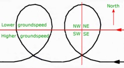 Some preliminary refresher notes The airspeed at which an aircraft stalls depends in part on the wing loading — the ratio of lift force generated to aircraft all-up mass expressed in units of 'g'. If a wing reaches the critical angle of attack under an aerodynamic load higher than 1g, the stalling speed will be higher than the normal 1g stall speed for that particular mass and wing configuration, and the effects of that accelerated stall are usually more pronounced than a 1g stall. An accelerated stall is not a 'high-speed' stall — the latter is one form of accelerated stall. Uncoordinated or cross-controlled flight: applying pressure to the rudder in one direction with opposite aileron applied is cross-controlling. This is, normally a rather sloppy way to fly but also a condition that can lead to an uncommanded roll if you inadvertently exceed the critical angle of attack — particularly in uncoordinated climbing or lower speed descending turns, such as in the approach to landing. It may also be the condition when a mis-rigged aircraft flies 'one wing low'. That being said, a planned and properly executed cross-controlled sideslip during final approach IS a normal and safe flight manoeuvre. Once established in a coordinated level turn, the lower inner wing has a slightly lesser airspeed and thus less lift than the outer wing, which produces a tendency for the outer wing to rise and the bank angle to increase. This requires the pilot to apply a slight opposite pressure to the control column which is known as 'holding-off bank'. This is quite normal and the pilot may not notice doing so because it is just part of maintaining the chosen bank angle throughout the turn. In a climbing turn, the outer wing has a slightly greater effective aoa than the inner wing and thus additional lift. Combined with its faster speed, this reinforces the tendency for the bank angle to increase and the need to hold-off bank. However, in a descending turn, the steeper path of the inner wing means that it will have a larger effective aoa than the outer — which may compensate, or over compensate, for the faster velocity of the outer wing. In order then to maintain the required bank angle, it may be necessary to apply a slight inward pressure to the control column; i.e. in a coordinated descending turn, the bank may be 'held on'. Should an aircraft be stalled inadvertently in a coordinated turn, both wings usually display the same progressive stall pattern — thus there should be no pronounced wing drop. When flying at speeds below 1.3 times Vs, the aileron moments are much less effective than at cruise speeds and larger aileron deflections are needed to bank the aircraft. There is always a tendency to be more forceful than necessary, thus overbanking the aircraft at a critical stage. The same applies to rudder effectiveness, so more coordinating rudder is required at slow speeds. In the following text, 'top/bottom rudder' refers to the relative position of the rudder pedals when turning; 'top' being the rudder pedal opposite the lower wing. Thus, if the aircraft is banked and turning to the left, then pressure on the right rudder pedal will apply top (or outside) rudder or pressure on the left rudder pedal will apply bottom (or inside) rudder. An excess of bottom rudder produces a skidding turn. Too much top rudder produces a slipping turn or may even halt the turn, thus producing a full sideslip. In a coordinated turn, there is just sufficient bottom rudder applied to keep the slip ball centred. 3.16.1 Awareness of angle of attack increase in a turn As a consequence of providing the centripetal force for a sustained turn, the lift force (i.e. wing loading) must be increased as angle of bank increases. Lift increases rather slowly up to a bank angle of 30° — where it is 15% greater than normal level flight loading — after which it increases rapidly, being 41% greater at a 45° bank angle. At this angle, the load on the airframe is 1.41g. The right-hand column in the following table shows the increase in stall speed, which is proportional to the square root of the wing loading. You can see that the percentage increase in stall speed is about half the increase in lift force. Bank angle Cosine g load (lift increase) Vs multiplier (increase) 10° 0.98 1.02 (+2%) 1.01 (+1%) 15° 0.965 1.04 (+4%) 1.02 (+2%) 20° 0.94 1.06 (+6%) 1.03 (+3%) 30° 0.87 1.15 (+15%) 1.07 (+7%) 40° 0.77 1.30 (+30%) 1.14 (+14%) 45° 0.71 1.41 (+41%) 1.19 (+19%) 50° 0.64 1.56 (+56%) 1.25 (+25%) 54° 0.59 1.70 (+70%) 1.3 (+30%) 60° 0.50 2.00 (+100%) 1.41 (+41%) The lift force increase in a constant-speed turn is provided by an increase in the lift coefficient [CL], which in itself is brought about by increasing aoa. Obviously, increasing CL implies an increase in drag and loss of height, or change in the rate of climb/descent, unless power is increased. A rule of thumb for light aircraft with normally cambered wings is that each 1° aoa change — starting from 2° and continuing to about 14° — approximates to a 0.1 CL change, and each 0.1 CL increase/decrease at a constant airspeed represents a wing loading change of roughly 8%. So, from the table above, a 30° bank angle in a sustained turn adds 2° to the basic aoa for the airspeed, a 45° bank angle adds 5° and a 60° angle adds 12°. The basic aoa for normal descending and climbing speeds in the circuit are probably around 6–8° and 6–10° respectively. Anything more than a moderate 30° banked turn decreases the safety margin between the effective aoa of some sections of the wing and the critical aoa. Wing loading must also change with the payload carried, as does the stall speed and the performance speeds. If a recreational light aircraft is normally flown with just the pilot on board, the aoa associated with a particular calibrated airspeed is significantly less than when flying at the same airspeed with a heavy passenger and perhaps a full fuel load. For example, suppose the aircraft is normally flown with only the pilot on board and an all-up weight of 400 kg. But when flown with a heavy passenger and full fuel, then all-up weight increases to 540 kg. Then the wing loading increases by 35%, thus CL and the aoa for any particular CAS will be greater than the pilot is accustomed to — maybe 2° or 3° at low airspeeds — and much less at high airspeeds. 3.16.2 Loss of control in an uncoordinated level turn If an aircraft is being held in a level turn at a particular bank angle with constant power, and excess bottom rudder is applied and held, the aircraft will rotate about the normal axis (yaw) in the direction of rudder deflection. Airspeed over the outer wing increases slightly while that over the inner wing decreases, thereby producing a lift differential; thus there will be a secondary roll effect that increases the bank angle. At the same time, the yaw increases fuselage drag and decreases airspeed — and thus lift — and the nose drops a little. This is an uncoordinated skidding turn, which often happens when the pilot tries to 'hurry' the turn with bottom rudder instead of increasing bank. We have a situation where the aircraft is overbanking with the nose yawing inward and downward. If the pilot reacts by applying and holding opposite aileron to restore the required bank angle — i.e. holding off bank — then due to the downward deflection of the inner aileron, the outer 30% or so of the lower wing is flying at a much higher aoa than the corresponding section of the higher wing. (If equipped with flaperons, the whole lower wing would be flying at a higher aoa.) The lower wing will also be producing more aileron drag, so the inward and downward yaw will increase and there will be a tendency for the pilot to raise the nose by increasing control column back pressure. This increases aoa overall, while at the same time speed will continue to decrease because of the increased fuselage drag, unless power is increased. The pilot is now 'pushing the design manoeuvring flight envelope'. Any consequent tightening of back-pressure on the control column to raise the nose (or any inadvertent back pressure applied when, for instance, looking at something of interest below you; looking over your shoulder; being distracted by fiddling with something in the cockpit; using the radio; or even any encountered atmospheric turbulence, wake turbulence or gust shear) may take the aoa of the inner wing past the critical angle. The aircraft loses its lateral stability (i.e. positive roll damping) and it is most likely that the lower wing will drop in an uncommanded roll, and thus become increasingly more deeply stalled than the upgoing wing — which may not be stalled or just partly stalled. If that initial roll is not promptly recognised as a stall or partial stall and it is allowed to continue — or perhaps it is incorrectly countered with opposite aileron without first unstalling the wing(s) by easing forward on the control column — then the increasing aoa of the lower wing deepens the stall and causes greatly increased asymmetric drag. Additional yawing forces in the same direction as the lower wing come into play, the nose-down pitching moment increases and the nose drops further. This is the incipient spin condition where autorotation is about to commence, which will happen quickly and in some aircraft very quickly indeed. The result is the stall/spin fatality you hear about when an unwary pilot allows such to develop without sufficient height to recover; and of course you say 'How sad it is for the family' — while thinking — 'but I'm too wary to get caught by such a simple mistake! But you don't know how many times you have come within a hair's breadth of eternity without being aware of it. If the cg is aft of the rearward limit, the amount of elevator deflection needed to bring the aircraft to the critical aoa is reduced; i.e. just a relatively small rearward movement of the control column may rotate the aircraft to the critical aoa. If MTOW exceeds the design limit and/or the cg is aft of the rearward limit then recovery from the initial stall may be impossible. The rules to avoid such situations are: • always maintain a safe speed near the ground consistent with the bank angle employed • continually envisage the wing aoa; i.e. how it's flying • keep the slip ball centred; i.e. never apply an excess of bottom rudder in an attempt to tighten any turn if height is below the safe recovery height (3000 feet agl perhaps) for a fully developed spin. Height loss in a stall/spin incident The height lost during a normal stall and recovery incident in a very light aircraft is probably between 50 and 250 feet depending on the aircraft type, the aircraft attitude at stall and the pilot's awareness. Loss of height in a stall/spin event is very much greater — perhaps 100–300 feet during the incipient stage, 200–400 feet to stop the autorotation and 300–500 feet during the recovery: a total of 600–1200 feet. This is why low-level stall/spin events are so deadly. 3.16.3 Loss of control in an uncoordinated descending turn The precursors to a stall/spin event in a low-power descending turn are the same as those for such an event in a level turn: if an excess of bottom rudder is applied, the aircraft will be skidding. Unless some other factor is dominant, then whenever an aircraft is slipping or skidding in a turn, the wing on the side to which the rudder is deflected will usually stall before the other, resulting in a consequent instantaneous roll in that direction. At descent speeds, the aircraft is usually flying at a higher CL and thus higher aoa, than when on the downwind leg (for example) — so there is a reduction in available aoa margin before allowing for the additional aoa required for the turn. The descending turn from base leg onto the final approach to landing is the most obvious place for a pilot to attempt to hurry a turn with rudder, because of the need to align with the runway. A tailwind component on base leg in a crosswind landing will increase the tendency to hurry the turn with rudder, as may other crosswind situations. If skidding, the excess bottom rudder is yawing the nose down and the tendency is to use elevator to keep it up, which is going to bring the aoa towards critical. Also, because of illusory ground reference cues, there may be a tendency to increase the rate of turn by applying additional bottom rudder whilst maintaining the bank angle with opposite aileron — 'holding off bank'; and you should never hold-off bank in a descending turn. If control column back-pressure is purposely or inadvertently applied, the aircraft may enter a cross-controlled stall where it is going to snap further into the bank and enter an incipient spin. Apart from the turn from base to final, such stalls might occur on final when avoiding a bird strike; or attempting a late correction to an out-of-line crosswind approach; or any time when you try to hurry a turn with bottom rudder. Stalls on the final approach — caused by failing to increase power when raising the nose to stretch the approach or reduce a high sink rate — will be exacerbated if the aircraft is also slipping. Probably the most dangerous low-level descending turn is the turn-back following engine failure after take-off; see 'The turn-back; possible or impossible — or just unwise? '. If flying cross-controlled when banked with an excess of top rudder — as in the sideslip manoeuvre, or a slipping rather than skidding turn — then if the aircraft stalls, the roll will probably be anti-spin; i.e. in the direction of the upper wing — towards an upright position — which is not quite so alarming and provides a little more time to react and reduce aoa. 3.16.4 Loss of control in a low-level climbing turn As we saw above, the increased lift force in the turn is provided by an increase in aoa. Now what will happen if you are climbing at Vx (the speed for maximum climb angle) using maximum power and decide (because of rising terrain or other obstruction, an approaching aircraft or just natural exuberance) to make a quick 30° left turn using a 45° bank angle, while still maintaining the climb? Coordinated climbing turn: if you do not keep a close eye on the ASI and the airspeed has decayed just a little, the general aoa at Vx could be around 12°. To initiate a 45° bank turn, wing loading and thus aoa must increase by 41%, which will take the aoa to 17°; i.e. past the critical stall aoa of 15° or 16°. Such full-power stalls in a coordinated climbing turn tend to result in the outer wing stalling first — because in a climbing turn, the outer wing has a slightly higher aoa than the inner — with a fairly fast outer wing and nose drop. The roll towards the outside of the turn would initially level the wings, but the increasing aoa of the down-going wing continues to accelerate the loss of lift and increases the drag on that wing. This is a particularly rapid action if the propeller torque effect is such that it also reinforces the roll away from the original direction of turn. P-factor may also cause the aircraft to yaw when flying with high power at high angles of attack. Such stalls are likely to result in a stall/spin event if corrective action is not taken as soon as the initial loss of roll stability — the uncommanded roll, or just a wing rocking warning — is apparent. Cross-controlled climbing turn: if the turn is skidding — i.e. with excessive bottom rudder applied —then the lower wing may stall first with the consequent roll into the turn because only one wing is stalled. This may be sufficiently pronounced to flick the aircraft onto its back. The propeller slipstream from a tractor engine will also be slightly asymmetric, as it supplies more dynamic pressure and thus lift to one wing while reducing the effective aoa. We will discuss cross-controlled climbing turns further when we look at illusory ground reference cues. Even a 30° banked climbing turn at a Vx will produce an aoa of 14°. This is very close to the critical aoa and provides no margin for even minor turbulence, slight mishandling or inattention. Of course, climb performance will be degraded unless extra power is available, which is unlikely because full power is normally used for the climb until a safe height is reached. The aoa margin, which you should always have in hand to cope with such likely events, is 3 or 4°. This indicates that, when climbing at Vx, turns should not be contemplated. When climbing at Vy — the best rate of climb airspeed with aoa around 8° — until a safe height has been gained, turns should be limited to rate 1 (180° in azimuth per minute, requiring about 15° bank) to ensure an additional margin if wind/gust shear is encountered in the climb-out. When entering a turn during a full-power climb, the aircraft must slow because of the increased drag at the higher aoa with no excess power available to counter it, so the aircraft's pitch attitude must be reduced sufficiently to maintain safe airspeed. Although recreational light aircraft — with their low wing loading — normally display quite benign stall characteristics when slowly decelerated to stall speed in straight and level flight, they will exhibit quite different behaviour when a stall is initiated during an uncoordinated turn; and such is the usual unintentional stall situation. Under these circumstances, the height lost during the incipient spin plus recovery — i.e. before developing autorotation — may be 200 to 400 feet or more. Thus, a wing-dropping stall event is highly dangerous when occurring in the circuit pattern or in any other low-level flight situation. 3.16.5 Standard recovery procedure for all stall types One standard recovery procedure is generally applicable to all stall events or attitude upsets in a three-axis aircraft, whether or not overbanked and/or overpitched — i.e. nose high/low — though this recovery procedure is not applicable to a fully developed spin, whether erect or inverted. Stall recovery generally requires the following concomitant stages: Ease stick back-pressure to reduce aoa of the most stalled wing below critical — which immediately gets the aircraft flying and restores normal 3-axis control. For any aircraft type, the amount of elevator deflection required to unstall the most stalled wing depends on many variables and may range from just an easing of back-pressure to a firm but smooth push towards the neutral position. All aircraft have their own handling idiosyncrasies and pilots must be aware of them. The nose should be positioned sufficiently below the horizontal to achieve safe flying speed while still well clear of the terrain. It's a matter of balancing height loss and proximity to terrain against a quick return to a safe flight speed. If the forward stick movement is both excessive and abrupt, the result could be an aoa movement below the zero-lift aoa, in which case there will be a reversed lift force on the wings that hinders recovery. This may be particularly apparent with trikes. The negative g due to the bunt could adversely affect some engines at a critical time. In instances of extreme overbanking (past 60° or inverted) — where although the upset may be the result of a cross-controlled stall or perhaps wake turbulence — the inverted or near-inverted wing will not be stalled but the aircraft will be in an inverted descent. The forward control column movement is needed to reduce the angle of descent. However, there may be the possibility of an inverted stall if the control column is pushed into its extreme forward position. Warning: never pull BACK on the control column as the initial response to a perceived stall or an overbanked nose-low attitude. Halt downward wing movement with rudder or centre the slip ball. Increase power smoothly, possibly up to maximum. The slipstream will also increase rudder and elevator authority, and aircraft stability, through its effect on fin and horizontal stabiliser; though if the aircraft is near the wings-vertical position — or is inverted — the throttle must be closed. In the recovery from a stall in a climbing turn, full power should be maintained unless the nose is pitched too far down. Roll the wings level with aileron so that all the lift force will be directed away from the ground. If inverted, choose the roll direction that provides quicker return to a wings-level attitude and, of course, the right way up. Following the preceding actions: adjust power as necessary; if flaps were fully lowered then adjust by stages to take-off position; hold attitude until speed has built up to Vy (perhaps Vx if there are terrain problems); then ease into a climb to a safe altitude, where you can assess what went wrong. Never attempt to continue a landing approach after such an event; go around, allowing plenty of time to assess the environment before re-approaching. If the aircraft is properly balanced (i.e. cg is within the limits for that all-up weight), any cross-controlled stall condition is readily countered. Of course if the pilot doesn't wait for the airspeed to build to a safe speed before again applying control column back-pressure, there will be a high risk of a secondary stall which may be very hazardous, depending on the height loss from the first stall. A document titled 'Don't stall and spin in from a turn' expands the material presented on this page and is available in the 'Decreasing your exposure to aerodynamic risk' guide. 3.16.6 Succumbing to illusory ground reference cues It is thought that some ground reference optical illusions may be a contributory factor in situations of loss of control near the ground. Such illusions can cause no problem in the circuit if the pilot confines external scanning to the intended flight path and checks for conflicting aerial traffic, while maintaining the appropriate instrument scan and a minimum safe flying speed. The latter is 1.5 times Vs, or perhaps as low as 1.3 times Vs in the latter part of a stabilised final approach as long as bank angle never exceeds 20°. Fixing the circuit pattern on particular ground reference points, rather than the landing strip (for example "turn downwind around the big tree"), may contribute to illusory ground reference cues. Wind drift illusions When wind speed is reasonably high relative to aircraft speed, then the aircraft's drift with reference to the ground is very apparent to the pilot operating at lower levels, and particularly at short, difficult airstrips. The diagram above represents the ground track of an aircraft conducting a level 720° coordinated turn with constant speed and constant bank angle, such that in the second 360° turn, the aircraft would be encountering its own wake from the first 360° turn — assuming that the wake didn't sink below the flight path. The movement of the air mass in which the aircraft is borne is toward the west (with an easterly wind) and the turn is clockwise when viewed from above. When in the region above the red line, ground speeds will be lower; when below the red line, ground speeds will be higher. The separation of the tracks for each 360° is exaggerated for clarity. When entering the south-west quadrant of the first 360°, the ground speed is initially high but reducing. The drift away from a central ground reference would provide the illusion of skidding out of the turn. Passing through the north-west quadrant, the skidding illusion will disappear as ground speed reaches the minimum. Ground speed starts to increase through the north-east quadrant. However, the increasing drift towards the reference point provides a very noticeable illusion of a slip into the turn. This reaches a maximum as the aircraft enters the south-east quadrant, where it abates as ground speed increases. So, in a 360° coordinated level turn with constant speed and constant bank, the aircraft (and its wake) drifts downwind relative to the ground at the wind speed rate. The cockpit instruments will of course show a constant airspeed, bank angle and a centred slip ball. However, the reference cues seen by a pilot looking at the ground during a low-level turn indicate increasing and decreasing airspeeds, alternating with decreasing and increasing slip. The downwind turn An unaware pilot may get into a difficult situation in the low-level circuit when an aircraft is turning 90° from crosswind to downwind (as in the progress through the SE quadrant of the diagram above), when drift cues create an illusion of slipping into the turn. At the same time, the increasing ground speed might suggest increasing airspeed. The reaction of an unwary pilot is to increase bottom rudder pressure. This will increase the bank angle and lower the nose. The pilot's reaction may well be to apply opposite aileron to reduce the bank, while increasing control column back-pressure to bring the nose up and possibly reducing power to reduce airspeed. Thus the aircraft is cross-controlled and flying at an aoa with little margin in reserve. This is coupled with decreasing airspeed, reducing lift and the aircraft sinking with a consequent increase in effective aoa. Under such circumstances, there is a likelihood of the aircraft stalling and snapping over. The downwind turn illusion seems to have more potential for error if the aircraft is climbing in a downwind turn. Note: sometimes you may read material which purports that an aircraft loses airspeed and might stall when turning from crosswind to downwind because the aircraft is changing direction relative to the wind direction, which of course is nonsense. However, airspeed must decrease in the turn if power is not increased to counter the extra induced drag. Although an aircraft can only stall if the critical angle of attack is reached, a combination of aircraft inertia and a wind shear or turbulence event encountered in the turn could result in a stall (particularly if it is still climbing) or, more likely, a loss of height. If turning very close to the ground to follow a particular ground path (close to trees when stock mustering, for example) the increasing drift into the turn must be allowed for. If you have doubts then imagine operating at 3000 feet agl with a 35 knot gradient wind and using the upper side of a layer of smooth stratus as the airfield surface for simulated circuits. Fly three squares, each leg of one minute duration, at 1.5xVs1 and 400–500 feet above the layer, making 30° balanced turns at the corners. Vary the alignment of each square by 30° in order to achieve near-crosswind alignment in at least one circuit. You will notice that 'ground-speed' does not vary in any part of each circuit (except for a small reduction in airspeed during every balanced turn), there are no drift illusions and nothing changes when turning from crosswind to downwind. You will also notice that in these conditions there is little turbulence. Pivotal height and reversal height Pivotal height or pivotal altitude is a term used by proponents of ground reference manoeuvres such as 'eights on pylons'. It is one particular height above ground at which, from the pilot's sight line, the extended lateral axis of an aircraft doing a 360° level turn (in nil wind conditions) would appear to be fixed to one ground point, and the aircraft's wingtip thus pivoting on that point. Imagine an inverted cone with its apex sitting on the ground reference point and an aircraft flying around the periphery of its inverted base while maintaining a constant airspeed. The vertical distance from the reference point to the centre point of the inverted base is the pivotal height, and the distance from the edge to that centre point is the turn radius. The bank angle is formed between the outer wall of the cone and the radius line. The pivotal height in nil wind conditions is readily calculated by squaring the TAS in knots and dividing by 11.3. So any aircraft circling at a speed of 80 knots would have a pivotal height (80 × 80 / 11.3) around 550 feet, no matter what the bank angle. In other than still air conditions the pivotal height varies with the ground speed. If the wind was northerly and the aircraft was turning anticlockwise (viewed from above), then ground speed would be lower on the eastern side of the turn and higher on the western side. When in the northern quadrant the aircraft would be drifting towards the centre point, while in the southern quadrant it would drift away. Drift would not be noticeable in the eastern and western quadrants but changed ground speeds would. At 70 knots ground speed, the pivotal height is reduced to 450 feet; at 90 knots it is about 750 feet. (Thus an exercise requiring a continuous 360° balanced turn at constant speed around a ground reference point, whilst holding pivotal height, involves continually changing the height above ground so that the line of pivot around each point is held constantly — rather than maintaining a constant distance from the 'pylon'. The bank angle must also be changed constantly as the wind drifts the aircraft towards or away from the pivot point. It is not an easy exercise to do well, and requires an ability to manoeuvre accurately whilst including the ground reference point in the normal scan pattern. Usually two ground reference points, about five seconds apart, are included for a figure eight pattern — otherwise known as 'eights on pylons'.) Now imagine two cones — the upper one is the inverted cone with the aircraft flying around the edge of its inverted base and below that is a second cone with its base on the ground and its apex connecting with the apex of the upper cone. The vertical distance from the ground through the cone intersection to the centre point of the inverted base is the aircraft height. So when an aircraft is turning at pivotal height in nil wind conditions, the wingtip appears to be fixed to a single point in the landscape. But when at any height other than the pivotal height, the wing tip will appear to move across the landscape. When an aircraft is turning at a height greater than the pivotal height, which is the normal situation in flight, the wingtip appears to move backwards over the landscape — path A in the diagram. However, when an aircraft is turning at a height less than the pivotal height (thus close to the ground), the wingtip appears to move forward over the landscape — path B in the diagram. Thus, when a turning and descending aircraft descends below pivotal height there is an apparent reversal of the wingtip movement from backward to forward, which is the reason pivotal height is sometimes termed reversal height. There is some thought that the reversal illusion may cause problems to unaware pilots during the final turn on approach to landing, because the turn may well pass through reversal height — at 50 knots ground speed, the reversal height is about 200 feet, at 60 knots it is about 300 feet and at 70 knots it is about 450 feet. If the aircraft is in a banked turn below reversal height, and if the pilot looks down over the wingtip, she/he may get the impression that the aircraft is not turning and may then add additional bottom rudder so that the wingtip then appears to move backwards in the turn — the normal movement. This will cause a yaw and the aircraft's nose will slide down. The aircraft may then appear to be nose-low, and the pilot's reaction is to increase back pressure on the control column. Low speed, excessive bottom rudder and an increasing control column back pressure are the prerequisites for the aircraft to stall and roll toward the lower wing — an incipient spin entry. All pilots should be aware of this illusion and that wind drift will exacerbate it — the turn to final approach is probably the most important ground reference manoeuvre that recreational pilots regularly perform. 3.16.7 Effects of wind shear Shear sources Air flow in the atmospheric boundary layer is normally turbulent to some degree but such turbulence does not significantly alter the aircraft's flight path. Bear in mind that what is a minor variation in flight path at a reasonable altitude may be hazardous when operating at slower speeds very close to the ground in take-off, landing, 'go-around' or perhaps cattle mustering operations. The velocity of near-surface winds is changing constantly; fluctuations in direction of around 20° and in speed around 25% either side of the mean occur every minute. In an unstable boundary layer, the rising air in thermals is accompanied by down-currents from the top of the layer, where the wind velocity approximates the gradient wind — i.e. the direction is backed by 20–30° from the wind at the surface, and the speed is greater. The descending air retains most of these characteristics when it arrives at the surface, thus the gust will back and increase in speed. Except for the vortex turbulence from the wake of preceding aircraft — which is extremely hazardous to light aircraft at low levels because of its horizontal rotational properties — practically all turbulence hazardous to flight is a result of wind shear, a sudden "variation in wind along the flight path of a pattern, intensity and duration, that displaces the aircraft abruptly from its intended path and sufficiently that substantial control action is needed." The shear is the rate of change of wind speed and direction, and its effect on flight can range from inconsequential to extremely hazardous. Vertical shear is the change in the (roughly) horizontal wind velocity with height; i.e. as the aircraft is climbing or descending. Horizontal shear is the change in horizontal wind velocity (i.e. speed and/or direction — gusts and lulls) with distance flown. Updraught, downdraught or vertical gust shear is the change in vertical air motion with horizontal distance. Wind shear can derive from many sources — orographic, frictional, air mass instability, convective downbursts, wave disturbance and thermalic; for a full description see microscale meteorology and atmospheric hazards. The closer to the surface that the shear occurs, the more hazardous it is for aircraft, particularly for low-momentum aircraft. For an aircraft taking off or landing, the shear may be large enough and rapid enough to exceed the airspeed safety margin and the aircraft's capability to accelerate or climb. Thermals as such contribute relatively minor amounts of hazardous turbulence in temperate climates, but can produce very severe turbulence when flying in the superadiabatic conditions common to inland Australia. Changes in aoa and lift Imagine an aircraft flying straight and level that suddenly encounters an area of substantial atmospheric downflow. Due to its inertia (which is a function of mass), the aircraft will momentarily maintain its velocity and flight path relative to the Earth. During that time the 'effective airstream' around the wings will no longer be aligned with the flight path but will have acquired a vertical component. The effective aoa, and consequently CL, will reduce. This produces a momentary reduction in wing loading, the airframe will experience a negative acceleration and the pilot will be restrained by the harness while the seat drops away from her/him. Following initial entry into the downflow, the inertial effects are overcome and the aircraft will restore itself to its trimmed angle of attack. Flight will continue normally, except that the new flight path will incorporate a rate of descent relative to the Earth and equivalent to the atmospheric downflow; i.e. drift now includes a vertical component — sinking air. When the aircraft flies out of the downflow it will again momentarily maintain its flight path relative to the Earth. During that time, the effective airflow around the wings will no longer be directly aligned with the flight path but will have acquired a vertical component opposite to that at entry. The aoa, and consequently CL, will increase. This produces a momentary increase in wing loading, the airframe will experience a positive g load and the pilot will feel the seat pushing up before the aircraft is finally re-established in level flight. A reversed sequence is applicable when encountering upflow; thus encountering changes in vertical flow causes momentary changes in aoa and wing loading, with some variation in the vertical profile of the flight path. If an aircraft is flying straight and level and suddenly encounters a head-on increase in wind speed, then due to its inertia the aircraft will momentarily maintain its velocity (and flight path) relative to the Earth. Thus there will be a momentary increase in air velocity over the wings with subsequent increase in lift. The aircraft will rise until the inertial effects are overcome, then the aircraft restores itself to straight and level flight at an altitude a little higher than previously. Similarly, if the aircraft encounters a head-on decrease in wind speed, then lift will momentarily decrease and the aircraft will sink until the inertial effects are overcome. Thus encountering changes in horizontal flow causes momentary changes in lift with consequent variation in the vertical profile of the flight path. The foregoing is just illustrative, because wind shear events are always a combination of speed variations and three-dimensional variations in direction. Various scenarios have been outlined above where the aircraft could be flying with little margin between effective and critical aoa; it is on occasions like these that Murphy's Law springs into action. What can and will go wrong at those worst possible times is an encounter with wind shear that suddenly increases the effective aoa of the wing and instantly switches on a stall/spin event. A more detailed document about coping with wind shear and turbulence' is available in the 'Decreasing your exposure to risk' guide. STRICT COPYRIGHT JOHN BRANDON AND RECREATIONAL FLYING (.com)
 -
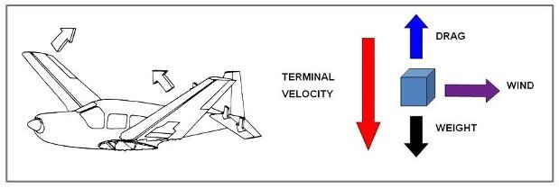 3.15.1 Airframe strength and elasticity Aircraft structures are designed to be as light as possible with some degree of structural flexibility while still providing adequate strength for the aircraft's operational category. To receive type certification, the design of a general aviation or recreational aircraft must conform with certain standards — among which are the in-flight structural load minimums — for the category in which the aircraft may be operated. In FAR Part 23, a recognised world standard for light aircraft certification, the minimum load factors that an aircraft at maximum take-off weight [MTOW] must be designed to withstand are: +3.8g to –1.5g (or –1.9g) for the normal operational category (which would include most factory-built recreational aircraft). +4.4g to –1.8g (or –2.2g) for the utility category (which includes most GA, and perhaps some RA, training aircraft). +6g to –3g for the acrobatic (i.e. aerobatic) category. +4g to –2g for the Light Sport Aircraft category manufactured in compliance with ASTM F2245-07 standard specification for design and performance of a Light Sport Airplane. Sailplanes and powered sailplanes are generally certificated in the utility or acrobatic categories of the European Joint Airworthiness Requirements JAR-22, which is the world standard for sailplanes; aerobatic sailplanes have limit loads of +7g and -5g. For more information see 'Limiting loads and ultimate loads'. There is an increasing risk of failure when exceeding the minimum load factors, and each instance of excessive loading will compound the failure risk. We use load factors in terms of g for convenience, but what we are also considering is total aerodynamic loading — remember that dynamic pressure increases with the square of the velocity; i.e. dynamic pressure = ½rV². Notes: 1. Uncertificated minimum ultralight aircraft, even with their low wing loading of perhaps 12 kg/m², can be overstressed readily just by flying at maximum level speed and increasing g in a pull-up (positive g) or a push-over (negative g). 2. Many aircraft are type certificated in both normal and utility category, and some are certificated in those plus the acrobatic category. In this case, the MTOW and cg limits are not fixed values, but vary according to the flight operating category. See the table in weight/cg position limitations. Weight and balance There are fixed limits to the payload an individual aircraft may carry safely. The payload must be distributed so that the aircraft's balance — the position of the aircraft's centre of gravity — is maintained within calculated limits. In addition, there is a maximum safe operating weight permitted by the aircraft designer. However, for many recreational aircraft, the MTOW will be limited by national legislation, which has nothing to do with aeronautical engineering. The aircraft's weight and balance very much affect control and stability at high speeds. Excess weight reduces the designed structural load limits, while cg positions outside the designated fore and aft limits may enhance unfavourable reactions to aerodynamic loads, affect stability, reduce controllability, or delay (or prevent) recovery from unusual or high-speed situations. Aeroelastic effects Elasticity is a property of certain materials that enables them to return to their original dimensions after an applied stress has been removed, see the notes on 'stress and strain' in the 'Builders guide to safe aircraft materials'. Elastic structures have a natural frequency of vibration and all aircraft structures exhibit some degree of elasticity; that is, they distort or deform a little, changing shape — flexing, elongating, compressing, bending and/or twisting — under applied aerodynamic loads; each type of distortion produces a particular mode of vibration. Transient structural distortions also contribute to a change in the aerodynamic forces, so the distortions and forces are mutually dependent. This is particularly so with the wings and tailplane. Wings have a low frequency bending mode of vibration where the tips flex up and down (i.e. flap) relative to the wing root, under changing flight loads — in turbulence for example. The degree of oscillation or flapping is more pronounced with high aspect ratio wings. While bending upward the wing adds a vertical velocity* to its forward velocity — the true airspeed — which results in a decreasing angle of attack (aoa) reducing the lift of the up-moving portion of the wing and thus causing an aerodynamic damping of the flapping oscillation. Similarly a downward bending motion results in an increasing aoa, increasing the lift of the down-moving wing and again causing an aerodynamic damping of the flapping oscillation. *A similar resultant velocity concept to a vertical gust encounter. Wings also exhibit a higher frequency torsional mode of vibration where they twist about the wing's elastic axis as the centre of pressure moves chordwise and consequently produces a spanwise variation in the aoa and changes the lift force and its distribution. If the centre of pressure moves forward it can then again increase the wing twist, aoa and lift, developing a non-stable situation. Twisting and bending distortions result in independent oscillations or vibrations and alter the effectiveness of lifting surfaces, though structural and inertial forces provide a natural positive damping that normally keeps vibratory energy in check. The elastic axis is defined as the line along the span of the wing where no torsion occurs when a loading is applied to the wing. A lifting force centred aft of the elastic axis will tend to twist the outer wing leading edge down, reducing aoa and thus aerodynamic force. A lifting force centred forward of the elastic axis will tend to twist the leading edge up, increasing the aoa and the aerodynamic force. The wing aerodynamic centre is usually designed to be close to or behind the elastic axis; if the aerodynamic centre is forward of the elastic axis then wing twist will increase aoa leading to the non-stable situation described in the preceding paragraph. The degree of torsional distortion is dependent on (1) the area of wing surface affected, (2) the distance between the aerodynamic centre and the elastic axis plus (3) the torsional stiffness (rigidity) of the surface. The torsional stiffness designed into the wing resists twisting, and structures usually revert to the normal status when the load is normalised. Aeroelasticity may lead to some problems at high speed, but reducing elasticity means increasing rigidity, which perhaps involves an unwarranted increase in structural weight. So, aircraft structural engineering must be a compromise between rigidity and elasticity. 3.15.2 Aerodynamic reactions to flight at excessive speed Flutter Wing structures are akin to a very-low-frequency tuning fork extending from the fuselage. When a tuning fork is tapped, the fork vibrates at a particular frequency; the stiffer the structure, the higher its natural frequency. The natural frequency of a wing or tailplane structure may apply another limiting airspeed to flight operations related to a self-exciting interaction between elastic, aerodynamic and inertia forces that result in 'flutter' of control surfaces and the structure to which the surface is attached. For example, when the airflow around a wing, tailplane or control surface is disturbed (by aerodynamic reactions, turbulence or pilot inputs) the structure's elastic reactions – twisting and bending – may combine as an oscillation or vibration of the structure that will quickly damp itself out at normal cruise speeds because of the structure's resistance. It is possible that the oscillation does not damp out but is sustained at a constant amplitude (perhaps felt in the airframe as a low-frequency buzz) that is not, in itself, dangerous but may contribute to structural fatigue. At some higher airspeed — the critical flutter speed, where the oscillations are in phase with the natural frequency of the structure — the oscillations will not damp out but will become resonant, rapidly increasing in amplitude. (Pushing a child on a swing is an example of phase relationships and amplification.) This flight resonance – flutter – is very dangerous, and unless airspeed is very quickly reduced, the increasing aerodynamic forces will cause control surface (or even wing) separation within a very few seconds. In 1966 NASA recorded a 24-second video of an in-flight flutter test on a Piper PA30 Twin Comanche demonstrating how rapidly stabilator oscillations increase in amplitude; Google 'NASA flutter video'. The following is an extract from an article by William P. Rodden which appeared in the McGraw-Hill Dictionary of Science and Technology; it provides a succinct description of flutter: "Flutter (aeronautics) — An aeroelastic self-excited vibration with a sustained or divergent amplitude, which occurs when a structure is placed in a flow of sufficiently high velocity. Flutter is an instability that can be extremely violent. At low speeds, in the presence of an airstream, the vibration modes of an aircraft are stable; that is, if the aircraft is disturbed, the ensuing motion will be damped. At higher speeds, the effect of the airstream is to couple two or more vibration modes [e.g. bending plus twisting ... JB] such that the vibrating structure will extract energy from the airstream [JB's emphasis]. The coupled vibration modes will remain stable as long as the extracted energy is dissipated by the internal damping or friction of the structure. However a critical speed is reached when the extracted energy equals the amount of energy that the structure is capable of dissipating, and a neutrally stable vibration will persist. This is called the flutter speed. At a higher speed, the vibration amplitude will diverge, and a structural failure will result." So, flutter is a vibrational instability that (if the structure is not sufficiently stiff) is generally related to the aerodynamic forces and thus the airspeed; but there are many flutter modes. Providing high torsional stiffness in an airframe structure — particularly a high aspect ratio wing — may incur weight penalties that are unacceptable for those aircraft whose MTOW is limited by national legislation, rather than normal design parameters. Mass inertia and the status of the control actuation systems are also involved in flutter development. Consequently ailerons, elevator or stabilator and the rudder (in that order) should be considered for mass-balancing, i.e. their centre of gravity is made coincident with their hinge centre line. This limits the mass moment of inertia so that the control surface does not rotate about its hinge line when the main structure moves; e.g. when the wing bends upward the aileron does not rotate downward but maintains the same floating position relative to the wing. It may be acceptable for the control surface to be over-balanced; i.e. its cg is slightly forward of the hinge line but under-balancing may achieve little. Mass-balancing of the control surfaces, including the rudder, should prevent flutter of that control surface, but the possibility of, for example, wing flexing/twisting flutter might still exist. Mass-balancing of ailerons might be accomplished by attaching moulded lead weight/s, or a lead-filled steel tube, within the nose of the control structure forward of the hinge centre line. As the moment arm, between that centre line and the centroid of the added weight, could be quite short the balance mass needed could be twice the mass of the unweighted control, so it is possible the end effect could be close to tripling the total weight of the aileron. Mass balancing of elevators might be achieved using a weight on an arm contained within the tail structure or within control horns, while a rudder might also be balanced by a weight within a control horn. The friction within aircraft control surface actuating systems adds to the damping of control surface oscillations and this damping ability increases as the oscillation frequency increases. So, it is important that all parts of the control actuating systems are made as rigid and secure as possible and checked to ensure that rigidity is always maintained so that control surfaces cannot deflect without a corresponding movement in the cockpit control. The possibility of destructive flutter increases if any of the following conditions exist: wear in control surface hinges, pulleys, fairleads or guides lack of tension, wear or slop in actuating pushrods/cables/conduited push-pull cables/cranks/torque tubes/turnbuckles safetying wire improperly installed faulty trim tabs. Also water or ice inside control surfaces or absorbed within a foam core; mud outside; additional surface coatings applied after mass balancing; tail buffeting caused by unsteady airflow related to, for example, alterations to the engine exhaust system; or other system anomalies that alter structural reactions also play a role in flutter development. Also see AC43.13-1B Chapter 7 'Aircraft hardware, control cables, and turnbuckles'. This is an extract from an RA-Aus accident investigation report: "(Witnesses) observed the aircraft in a steep dive at what appeared to be full power. The port wing appeared to detach from the aircraft ... The wing that tore away from the fuselage had the attach points intact but had pulled the mountings out of the top of the cockpit. This action would have released the door, which landed close to the wing. The wings were intact but the ailerons were detached. There was no delamination of the fibreglass structure. The ailerons were not mass balanced. The (prototype) aircraft was a conventional design being a high wing, monoplane of composite construction. While the fuselage was a proven design the pilot /builder had designed his own wing including the aerofoil section. The workmanship was excellent and there is no evidence of any lack of structural integrity. The eyewitnesses reported seeing a sort of 'shimmying' from the aircraft. It is believed that this shimmying was aileron flutter which led to the detaching of both ailerons. This same flutter condition would account for the massive forces required to detach the wing from the aircraft in the manner that occurred. Flutter could have been triggered by the wing aerofoil design combined with the manoeuvre the pilot was conducting or from the aileron control design ... The aircraft suffered a massive inflight structural failure almost certainly caused by severe aileron flutter and the aircraft speed in the dive. Any flutter would have been exacerbated by the lack of mass balancing." Vne — the standard limiting airspeed If an aircraft is operated within its specified flight envelope, observing the limiting accelerations and control movements, and maintaining airspeed commensurate with atmospheric conditions, then the only possibilities of in-flight structural failure relate to: improper modification, repair or repainting of the structure control actuating system deficiencies cumulative strain, or minor damages, in ageing aircraft failure to comply with the requirements of airworthiness notices and directives poor care and maintenance of the airframe. Flight at airspeeds outside the envelope (or at inappropriate speeds in turbulent conditions, or when applying inappropriate control loads at high speed) is high risk and can lead to airframe failure. Vne is the IAS, specified by the designer, which should never be intentionally exceeded in a descent or other manoeuvre. For a fuller description of Vne and how it is calculated see 'How fast is too fast?' in the 'Decreasing your exposure to risk' tutorial. Wing divergence Wing divergence refers to a state where — at very low angles of attack and high speed (when the nose-down pitching moment is already very high) — pressure centres develop, which push the front portion of the wing downward and the rear portion upward. This aerodynamic twisting action on the wing structure — while the rest of the aircraft is following the flight path — further decreases the aoa and compounds the problem. The action finally exceeds the capability of the wing/strut structure to resist the torsional stress, and causes the wing to separate from the airframe with no warning. This could be induced if turbulence is encountered at high speed. Control reversal As airspeed increases, control surfaces become increasingly more effective. They reach a limiting airspeed where the aerodynamic force generated by the ailerons, for example, may be sufficient to twist the wing itself. At best, this results in control nullification; at worst, it results in control reversal. For example, if the pilot initiates a roll to the left, the downgoing right aileron will twist the right wing, reducing its aoa and resulting in loss of lift and a roll to the right, probably with asymmetric structural loads. All of which would make life difficult when attempting to roll the wings level during recovery from a high-speed dive. Many of the uncertified minimum ultralights, and perhaps some of the certificated aircraft, have low torsional wing rigidity. This will not only make the ailerons increasingly ineffective with speed (and prone to flutter), but will also place very low limits on Vne and g loads. Vne may be so low that it can be achieved readily in a shallow descent at 75% power. Effect of wing washout Wings incorporating geometric washout have a significantly lower aoa towards the wing tips. At high speed when the wing is flying at low aoa, there are high aerodynamic loads over the wings. However, the outer sections could well be flying at a negative aoa and the reversed load in that area will bend the wingtips down, possibly leading to outer spar fracture. See the accident technical report below. Vertical gust shear and gust loads The effective aoa of an aircraft encountering an atmospheric gust with a significant vertical component (updrafts, thermals, downdrafts, microbursts, macrobursts and lee waves) will be increased momentarily if the air movement is upward relative to the aircraft's flight path, or decreased momentarily if the air movement is downward. Thus, an updraft will increase CL and lift, increasing the aerodynamic loading and lead to an upwards acceleration of the aircraft. The magnitude of the acceleration is determined largely by the change in aoa, the aircraft speed (the higher the speed, the greater is the g load), the design wing loading and the aspect ratio. The lower the design wing loading and/or the higher the aspect ratio, the greater is the change in load factor for a given increase in aoa and the easier it is to overstress the wings at high speed. The effects of shear and gust loads are expanded in the section on wind shear and turbulence. Other effects It is not just the preceding items that may be a problem at high speed. The maximum speed may be limited by the ability of the fuselage to withstand the bending moments caused by the loads on the tailplane necessary to counter the wing's substantial nose-down pitching moment at very low aoa, or the aoa changes due to vertical gust shear, or the extreme loads caused by a high speed pull-up. Applying rudder in a high speed pull-up applies twisting loads to the rear fuselage. Even a very small bird can cause severe damage in a high-speed bird-strike. When nearing the zero-lift angle of attack in a high-speed descent, many cambered wings suddenly experience a strong nose-down pitching moment and the aircraft will 'tuck under' rapidly; this will certainly make the pilot wish she/he was somewhere else. The symmetrical aerofoil wings often used in aerobatic aircraft don't have this problem. Also, the possibility of a runaway propeller in a high-speed dive is always there for those aircraft with a constant-speed propeller governor or perhaps an in-flight adjustable system. The following is a condensed version of an Australian Transport Safety Bureau Technical Analysis Occurrence Report. Note: the Coroner's findings in relation to the fatal accident near Atherton does not support any view that the accident was caused by pilot mishandling; rather, the Coroner's "preference is towards port side wing tip separation as a consequence of the un-airworthy state of the aircraft ..." "An Airborne Edge microlight aircraft impacted terrain during a 2005 flight to Atherton, in Far North Queensland. The pilot, the sole occupant of the aircraft, was fatally injured. In 2006 a similar Airborne Edge aircraft impacted terrain at Cessnock, New South Wales, also fatally injuring the pilot, the sole occupant of the aircraft. In both instances, RA-Aus initiated safety investigations to determine contributing factors to these accidents. During the course of these investigations, similarities in the structural failures of both aircraft were observed. In addition, a third accident involving an Airborne aircraft registered with HGFA with similar structural failure was identified. This accident had occurred in 1996 in Hexham, NSW. In order to determine possible connections between all three accidents, ATSB was asked to conduct technical examination and analysis on recovered parts from the Atherton and Cessnock accidents, to assist the RA-Aus investigation. Information regarding the 1996 accident was taken from coronial findings. In all three accidents, the failure of the main wingspars had occurred near the wingtip. Qualitative analysis of the structural design and loading of the part during this safety investigation and the examination of the coronial findings from the Hexham accident, revealed that all main wingspars had failed under negative G loading. Such loading was likely if the aircraft entered or encountered flight conditions outside the manufacturer's specified flight envelope. Examination of material characteristics of the failed wingspars did not show evidence of material deficiencies that could have contributed to these accidents. The manufacturer's operating handbook prohibited all aerobatic manoeuvres including whipstalls, stalled spiral descents and negative G manoeuvres. The manual specified that the nose of the aircraft should not be pitched up or down more than 45 degrees, that the front support tube of the microlight and the pilot's chest limit the fore and aft movement of the control bar, and that the aircraft should not exceed a bank angle of 60 degrees. Review of photographs of the Airborne Edge, indicate that the wing adopts a degree of twist while in flight. Twist will effect the load distribution by shifting some of the lift from the tips inboard (i.e. more lift is generated in the middle of the wing). Given the structural restraint of the tip struts and battens located at the tip of the trailing edge of the wing, the aerofoil at the wing tip must adjust and try to align with the relative airflow. This results in a smaller amount of lift generated near the wing tips due to a reduced angle of attack to the relative airflow." (Or an aoa reduced below the zero lift aoa, i.e. reversed lift ... JB) 3.15.3 Recovery from flight at excessive speed Generally, excessive speed can only build up in a dive, although just a shallow dive can build speed — and rate of descent — quite quickly. The table below is a calculation of the rate of descent after a few seconds at dive angles of 10°, 30° and 45° for a moderately slippery light aircraft. Dive angle Airspeed (knots) Rate of descent (fpm) 10° 100 1700 30° 150 7500 45° 180 12 500 Recovery from an inadvertent venture into the realm of flight near, or even beyond, Vne is quite straight-forward, but requires pilot thought and restraint in initiating recovery procedures, particularly so if the aircraft is turning whilst diving. Considerable height loss will occur during recovery, so the restraint is required when terra firma is rapidly expanding in the windscreen. Halt the buildup in airspeed by closing the throttle. Unload the wings to some extent by moving the control column to the neutral position or just aft of it. Keep the slip ball and the ailerons centred — the twisting action of excess rudder at very high airspeed may strain the tailplane and rear fuselage. Gently roll off any bank while using coordinated rudder; this will ensure the total lift vector is roughly vertically aligned. Maintain the control column position at neutral or slightly aft to avoid any asymmetric loading arising from simultaneous application of aileron and elevator at high speed. When the wings are level, start easing back on the control column until you are pulling the maximum load factor for the aircraft : +3.8g or +4.4g, perhaps less for some ultralights. Do not pull back so harshly that the aircraft enters a high-speed stall. Hold the applied loading near the maximum until the aircraft's nose nears the horizon, then level off. The aircraft will have sufficient momentum to reach this position before opening the throttle. If you have ample height at the commencement of recovery, then there is no need to pull such high g — particularly if the atmosphere is bumpy when gust loads, added to the high manoeuvring g, may prove excessive. In aircraft not certified for aerobatics, it is best to wait until airspeed is less than Va before pulling g — if circumstances permit. A problem with this procedure is that most light aircraft do not have an accelerometer [g-meter] fitted, so it is difficult to judge the g being pulled. However, if properly executed 60° steep turns are practised, then some idea of the 2g load on your own physiology can be gained. At the higher end of acceleration the average fit person will probably start feeling the symptoms of greyout by 4g. 3.15.4 Recovery from a spiral dive In a well-developed spiral dive, the lift being generated by the wings (and thus the aerodynamic loading) to provide the centripetal force for the high-speed diving turn, is very high, and much of it is directed inward. The aircraft is near the extremes of its design flight envelope, with very high aerodynamic loading and very high speed, well above Va. The pilot must be very careful in the recovery from such a dive, or damaging structural loads will be imposed. If rearward stick force is applied to pull the nose up while the aircraft is turning, the result will be a tightening of the turn and further lowering of the nose, thus dramatically increasing the applied loading or possibly prompting a very punishing high-speed stall. Also aileron to level the wings must be applied with restraint, the aileron on the lower wing will increase the aerodynamic force on the portion of wing ahead of it and move the centre of force further towards that wingtip, so increasing the moment of force at the spar root. The downgoing aileron is also applying a twisting force to the outer wing structure. Sudden or excessive aileron deflection at airspeeds well above Va could well lead to outer wing or full wing separation. Control reversal could also be a factor, see 'High-speed control reversal: will it always roll in the direction you want?' The recommended procedure — for a fixed undercarriage aircraft without propeller pitch control — is: Reduce power. Carefully centralise controls: the forward movement of the control column will partially unload the wings. Smoothly level the wings with aileron while the rudder and elevators are held in the neutral position. As the wings become level with the aircraft still diving at high speed, much of the lift that was providing the centripetal force will now be directed vertically (relative to the horizon); and if up elevator is applied, the aircraft may start a high g pitch-up — even into a half loop. Thus to prevent this, the pilot must hold the elevators in the neutral position while rolling level or even applying further FORWARD stick pressure — before applying aileron — to reduce aoa; but not below the zero-lift aoa, i.e. the load factor must remain positive. At high speed, the stick force required will be high, but the position of the elevator trim should not be altered. Also it is probably not wise to apply two controls simultaneously at very high speeds because of the consequent asymmetric airframe loading. Read this Australian Transport Safety Authority analysis of an inflight breakup most likely caused by excessive control force during spiral dive recovery. The theme common to all problems encountered when moving at very high speed is that there is no warning and little time to do anything about it! The only safe procedure is not to push the high-speed end of the envelope at any height: make gentle, smooth control movements and avoid asymmetric flight loads and never put yourself in the position where you may encounter non-visual flight conditions at low levels. 3.15.5 Notes: compressibility of airflow and Mach number These notes have little value for the recreational aviator, but are included for interest. Except for a slight EAS correction to IAS/CAS, and the possible propeller effects, the compressibility/elasticity of airflow (i.e. the density change resulting from pressure disturbances) does not have any significant airframe aerodynamic effects for aircraft operating at speeds below 200 knots TAS and altitudes below 10 000 feet. Pressure disturbances, or waves, propagate through the atmosphere in all directions, at the speed of sound. Mach 1.0 is the notation for the speed of sound. For aerodynamic purposes airflow speeds are classified within five ranges: Hypersonic flow — airflows greater than Mach 5.0 Supersonic flow — airflows between Mach 1.5 and Mach 5.0 Transonic flow — airflows between Mach 0.8 and Mach 1.5 Subsonic flow — airflows between Mach 0.3 and Mach 0.8 Incompressible flow — airflows below Mach 0.3 The term 'incompressible flow' doesn't mean that air is incompressible; it just indicates that at flow speeds below Mach 0.3 (30% of the speed of sound or about 200 knots TAS), local density variations within the flow — due to compressibility — are insignificant; so aerodynamicists can assume constant density within the flow. At subsonic velocities, significant density changes may occur in the airflow around wings, which will produce flow separation and a turbulent wake — wave drag. The associated drag coefficient builds rapidly at airspeeds above Mach 0.75 then reduces as Mach 1.0 is exceeded. The speed of sound in the atmosphere varies with air temperature. The Mach number is the measure of an aircraft's TAS in relation to the ambient speed of sound. For example, Mach 0.6 indicates that the aircraft's true airspeed is 60% of the speed of sound. The speed of sound is proportional to the square root of the absolute temperature. In the ISA, Mach 1.0 at sea level = 663 knots, and temperature at sea level = 15 °C [288 K]. Thus, if the temperature = −36 °C (237 K) then the ambient Mach 1.0 = 663 × √237/√288 = 601 knots. Thus, Mach 0.60 at 15 °C would be 398 knots TAS, while Mach 0.60 at −36 °C would decrease to 360 knots TAS. Below the tropopause — the speed of sound decreases as altitude increases. A machmeter is an instrument that measures and compares the speed of the aircraft and the speed of sound, using the outside air temperature. It adjusts for actual air density but is still subject to the same position errors as the ASI. The machmeter is usually incorporated within an ASI; the numeric Mach appears in a small window within the ASI dial. You may see references to design diving speed presented as 'Vd/Md' which indicates the speed may be expressed as IAS or Mach number. Other reference airspeeds are presented in similar fashion. For interest, the following table is the maximum permissable speed/altitude for a late 1940s/early 1950s piston-engined naval fighter — the Seafire 47: Altitude feet Max. IAS knots Mach no. Approx. TAS Sea level – 10 000 455 0.78 505 10 000 – 15 000 410 0.78 495 15 000 – 20 000 375 0.78 485 20 000 – 25 000 340 0.78 472 25 000 – 30 000 300 0.78 459 30 000 – 35 000 270 0.78 448 35 000 + 240 0.78 432 Subsonic jet transport aircraft are designed to cruise close to their maximum allowable speed — Vmo/Mmo. Vmo is the limiting indicated airspeed and Mmo is the limiting Mach number. Mmo is probably between Mach 0.80 and Mach 0.85. In normal operations the limiting airspeed is Vmo, up to a change-over pressure altitude (perhaps around 25 000 feet). Above this altitude Mmo becomes the limiting speed value because of compressibility problem restraints. Vmo could be shown as a fixed red line on the ASI (or 'Mach/Airspeed Indicator') but, because the speed of sound decreases as altitude increases, Mmo can't be represented by a fixed marking on the indicator. So, a moving red-and-white striped pointer, the 'barber pole', shows the limiting Vmo/Mmo varying with altitude. It shows the IAS corresponding to the lower of Vmo or Mmo for the current altitude. For further explanation read this Boeing flight operations review document. STRICT COPYRIGHT JOHN BRANDON AND RECREATIONAL FLYING (.com)
 -
 3.14.1 The landing sequence In this module we will look at the common factors to be considered in landing a normally configured, three-axis, fixed-undercarriage, nosewheel or tailwheel aircraft, which may or may not be flap-equipped. Aircraft designed with full 'short take-off and landing' [STOL] capability will use slightly different techniques in some parts of the approach and landing. There are differing landing procedures or techniques, or combinations thereof, applicable to airfield dimensions and surface conditions: normal landing short-field landing soft-field landing. The basic landing sequence is varied, according to prevailing conditions (and there is a varying degree of alignment correction to allow for the crosswind component of the wind velocity), but it usually has four parts: Joining the circuit pattern of the airfield, during which the aircraft is decelerated from cruise speed to circuit speed, the airfield is visually checked for serviceability and obstructions, surface wind direction ascertained from observation of the windsock(s), the whereabouts of other traffic is established, the landing direction and approach is planned and the pre-landing cockpit checks are carried out in a logical sequence. The approach to the landing, during which the aircraft is decelerated from circuit speed to the reference indicated approach speed [Vref], configured for landing, then finally stabilised at a constant speed and rate of descent with wings level and aligned — so that the flight path traced over the ground, during the final approach, is on the same line as the intended ground roll-out path. The stabilised approach should be established before the aircraft is at a height 300–400 feet above the runway/airstrip/landing area. Once established, only slight movements of the flight and engine controls should be necessary to maintain the approach. The flight path passes over an imaginary 50 feet high screen, placed at a short distance before the airstrip threshold. A transition period, where both the rate of descent and the forward speed are slowed during a 'round-out' or 'flare' prior to touchdown. The touchdown and subsequent ground roll, after which the aircraft is turned off the landing area at an appropriate taxiing speed. The arrival is complete when the aircraft is properly parked, the engine is properly shut down, any passenger is safely disembarked and the aircraft is secured. The most favourable conditions for optimum landing performance at, or near, maximum weight are: a pilot who exercises sound judgement, and follows the rules and recommended procedures a surface of ample length, which is dry and level, or with a slight upslope a low density altitude; i.e. low elevation and low temperature a smooth, full headwind of reasonable and constant velocity. 3.14.2 Factors affecting safe landing performance Apart from the pilot's physiological condition, airmanship, experience and capability — and the aircraft's weight and balance condition — landing performance is limited by the following constraints, all of which should be carefully assessed — both within the pre-landing procedure and at the flight planning stage — to establish whether a safe landing is viable. Generally most of the engine effects and other constraints affecting take-off performance, covered in section 11.3, have no significant effect on landing performance — except, with both tailwheel and nosewheel aircraft, the inertial effect of the cg position. However, when a landing attempt is aborted, then any of those constraints may be present during the initial go-around. Demonstrated landing distance. Landing distance is the total distance required to clear an imaginary screen, 50 feet (or 15 metres) high, placed before the airstrip threshold; then touch down and bring the aircraft to a halt with normal braking — in nil wind conditions. It should be borne in mind that the manufacturer's 'demonstrated' landing distance has been achieved by a very experienced test pilot in very favourable conditions, during the type certification tests. The landing distance required by the average recreational pilot may be considerably greater. Airfield dimensions and slope. The usable length of runways or strips must be ascertained, as well as the degree of slope — both with and across the direction of landing. Landing downslope will reduce deceleration and lengthen the ground roll. Slope across the landing path makes the touchdown and subsequent ground roll more difficult to control. At a 'one-way' airstrip a combination of airfield slope and rising terrain at the high end necessitates landing upslope, no matter what the wind direction. Airfield surface and surrounds. A short, dry grass or rough gravel surface might decrease the ground roll by 10% compared to that for a smooth, sealed surface. Wet or long grass might decrease the ground roll by 30%. However, there is a possibility that a wet surface can induce aquaplaning/hydroplaning, which adversely affects braking and/or can result in a ground loop (where the aircraft suddenly swings through 180° or more with probable undercarriage and propeller damage). Frosty grass provides little friction, so be wary in early morning shadowed terrain. Long grass and weeds can catch a wingtip, resulting in a ground loop. A soft or waterlogged surface might greatly decrease the ground roll but will increase the possibility of the aircraft tipping over during the ground roll, or may delay — or even prevent a take-off — if such is attempted during the landing ground roll. The location and height of constructed obstructions, trees and local topography must be assessed. Airfield density altitude. This is a critical factor that is often not correctly assessed. High density altitude has a major effect on the approach speed (i.e. the true airspeed is significantly greater than the indicated airspeed), and thus the ground speed at which the aircraft touches down and the length of the subsequent ground roll. High density altitude also affects the aircraft's climb-out performance if the landing is aborted. Re-read the section on high density altitude. Wind velocity and turbulence. Wind strength, direction, downflow, gust intensity, surface turbulence and the potential for wind shear events are normally the major considerations in landing performance. Read the micrometeorology turbulence module, but particularly the section on 'lee wind downflow and eddies'. You should also read the CASA Advisory Circular 'Safety during take-off and landing'. This is an abridged web version for recreational aviation. The pilot-in-command of an aircraft must assess all the foregoing factors and conditions to ascertain the total distance required for obstacle clearance and landing, judge if the landing can be conducted safely and ascertain a safe go-around route if the landing should need to be aborted. All the foregoing assumes that the height of the cloud base allows sufficient visibility, and appropriate terrain and obstruction clearance within the circuit. The problem for the less cautious pilot — if the airfield conditions are found to be unsuitable — is that an eventual landing is mandatory and, if flight planning is poor, there may be no acceptable alternate airfield within range. 3.14.3 The standard circuit pattern For at least the past 65 years, a standard procedure has been adopted for any piston-engine light aircraft approaching to land at a non-controlled public airfield. This procedure is called the standard circuit pattern and is adopted by convention rather than laid down by regulation. Following the pattern requires that an aircraft should track over at least three legs of a rectangular course aligned with the runway or landing strip that is most into-wind. Turns, once established within the circuit, will all be in the same direction, usually to the left unless terrain or ground habitation dictate otherwise. The downwind leg will be flown at moderate speed (adjusted to avoid overtaking preceding aircraft) and at a constant height — normally 1000 feet above the airfield level is recommended, but some primarily ultralight airfields may have a lower standard circuit height. And, of course, the aircraft must be operating in visual meteorological conditions [VMC] — clear of cloud and in sight of the ground at all times, if at or below 1000 feet agl. Check the visual meteorological conditions for aircraft operating under the visual flight rules. Consistency The height of the circuit is particularly important for ultralight pilots. Ultralight engines and associated systems are not renowned for their reliability and the circuit height should be sufficient that, following power loss, an aircraft flying a reasonably tight circuit has every chance of gliding to a safe landing area on the airfield. Pilots should adopt their own personal circuit procedures, to be used wherever possible; the principle being that consistency improves performance. Do not automatically apply the procedure utilised at a training airfield when operating elsewhere. The skills involved can only be assimilated by repeated practice at many airfields — not by reading books or web pages. Consistency is the key. Every circuit and landing should be performed to the best of the pilot's ability; such consistency makes the occasional difficult landing easy. The diagram below (adapted from the Sydney Basin Visual Pilot Guide, courtesy of the Australian Civil Aviation Safety Authority's Aviation Safety Promotion program) demonstrates the full routine for a piston-engine aircraft inbound for landing at a public airfield. The routine 1. The first stage is an overflight at a height not less than 1500 feet agl (preferably with Local QNH set, but if this is not obtainable, use Area QNH) to determine the airfield serviceability, the surface wind direction, the runway/strip being used by other traffic and confirmation of the circuit direction; or if no other traffic, to select the strip to be used. While in the circuit, keep monitoring the relative position and the movements of other traffic at all times. Note that the 'circuit area' is taken to cover the area within a radius of three nautical miles from the 'airfield reference point'. Assume that the latter is the runway intersection. If the airfield is unfamiliar, the overflight also provides the opportunity to examine the circuit area for safe escape routes from each runway following a late go-around. Also check the area for suitable forced landing sites and associated hazards should the engine fail during a go-around or after take-off. See the Coping with Emergencies Guide. 2. The second stage is to manoeuvre so that a let-down from 1500 feet is commenced on the 'dead' side of the active runway, tracking close and parallel to that runway. This is the upwind or into-wind leg. The first and second stages provide the opportunity to carefully check the airfield area and boundaries for hazards — animals, power lines and other wires, ditches, obstructions, and to ascertain the whereabouts of other traffic in, or joining, the circuit and to be seen by them*. All manoeuvring should be done so that the airfield activities always remain in sight; i.e. don't turn away for a short time and then follow with a reversed turn onto downwind. *The official term for this latter procedure is 'unalerted see and avoid', but it has its limitations. See the Australian Transport Safety Bureau research report 'Limitations of the see-and-avoid principle'. The report was first issued in 1991 when mid-air collisions in Australian general aviation averaged about one per year but collisions have increased slightly since then. Most — or nearly all — general and powered recreational aviation mid-airs occur in the circuit area, generally when one aircraft descends into another from behind. 3. When circuit height is reached and the upwind end of the runway has been passed, choose an appropriate position to turn onto the crosswind leg so that there will be no conflict with traffic on the crosswind and downwind legs, and to achieve optimum traffic spacing. You are now entering the traffic side of the circuit. Watch for aircraft joining the circuit on crosswind and for aircraft taking off; ensure that you provide adequate clearance. Maintain circuit height and, allowing for drift, track at 90° to the runway. 4. Turn 90° onto the downwind leg at an appropriate distance past the runway (after checking for aircraft joining the circuit on the downwind leg), check the crosswind drift against selected landmarks and adjust heading to track parallel to the runway, perform the appropriate downwind cockpit checks, and hold altitude and appropriate traffic spacing. Set power and trim the aircraft to maintain an airspeed that allows time to plan the landing without unnecessarily delaying other traffic — probably around 1.7 × Vso. Note: although we call these legs 'upwind', 'crosswind' and 'downwind', they are only nominally named so, because the surface wind is unlikely to be closely aligned with the 'into-wind' runway — particularly with a single strip — and the wind at circuit height might vary considerably from that at the surface. 5. Planning time! Pick an intended touchdown target on the airstrip. This should be far enough into the strip so that an undershoot on approach will still allow normal roundout and touchdown on the runway, or an overshoot on approach will still allow ample runway to bring the aircraft to a halt. For all ultralights and most light aircraft, the latter requirement is probably inconsequential for most runways at public aerodromes. A touchdown target maybe 400 feet from the threshold is about the norm; never target the beginning of the runway or strip for touchdown. Now choose another point, say 200 feet back from the touchdown target towards the threshold; this is the aiming point. Of course, it may be difficult to identify such positions at a featureless airstrip; also, the figures will vary according to the aircraft's drag characteristics in the landing configuration. We are presuming here that we are operating at the average recreational aviation airfield where the strip length may be 2000–3000 feet. It can be a little embarrassing for the light aircraft pilot who touches down 400 feet past the threshold of a 6000 feet runway and then has to taxi a kilometre to the next exit. At a certified aerodrome, the runway centre-lines are 100 feet [30 m] long with a 100 feet gap in between, and the 'piano keys' which normally mark the threshold are also 100 feet long. There should also be touchdown marks at 500 feet [150 m], 1000 feet [300 m] and 1500 feet [450 m]. 6. At an appropriate distance past the aiming point, turn 90° onto the base leg, and hold airspeed but reduce power so that a descent is started during the turn. Lower the first stage of flap if so equipped. Reduce airspeed (but not less than 1.5 × Vso), and trim. The time spent flying base leg is most important, as it provides the opportunity to: set up the aircraft in the approach attitude; establish a power and flap setting (and trim) for the required rate of descent; check for conflicting traffic both airborne and on the ground and particularly any traffic on a straight-in approach or very wide circuit; assess the crosswind component along the landing path; decide the touchdown technique appropriate for the conditions; and review the pre-landing checks. Hold an accurate heading on base to carefully monitor drift, comparing the wind velocity at that height with the surface wind indicated by the windsock(s). A significant difference between the two indicates wind shear will be encountered during the final approach — this may erode the safety margin between the approach speed and Vso, or cause other difficulties. Never be tempted to fly a semi-circular base with a short final approach — it is very poor airmanship and negates all the safety check features of the square base leg. It may be that preceding traffic conditions preclude a turn onto base at the optimum position — in which case you must reduce speed and/or extend the downwind leg further downwind; maintain altitude; and delay the start of descent, and some actions, until the aircraft is well into the base leg or even established on final approach. 7. Start a 90° descending turn onto the final approach so that, on completion of the turn, the aircraft is lined up with the extended notional centre(line) of the landing strip. During the turn, be aware of the reversal height phenomena and confine external scanning to the intended flight path and to the check for conflicting aerial traffic particularly ahead of and behind you. Watch for aircraft on or near the runway; if in doubt about safety initiate a go-around. If satisfied with the initial approach, then lower full flap (if the wind speed is fairly high, then partial flap may suffice), adjust airspeed to the recommended final approach speed [Vref] and re-trim. Once stabilised in the final approach, control the airspeed and the rate of descent with small movements of flight controls and throttle. The power setting should be such that it allows small power reductions, or power increases, in order to maintain the approach path. This can't be done if the approach is set up with the engine at idle power. In addition, the thrust response is not that effective from an idle setting and, for many aircraft, an approach at idle power will entail a high sink rate, which may be difficult to manage. Also, an idle power approach tends to over-cool the engine and may promote carburettor icing, both of which may result in high power not being available when needed — such as in a go-around. If flying an aircraft with a low approach speed into a relatively high wind************* 8. Continue tracking down 'final', whilst correcting for the crosswind component, and watching the position and apparent movement* of the aiming point relative to the windscreen. Then at 50 feet or so, substantially reduce the rate of descent, reduce thrust to zero, touchdown and roll-out until it is safe to turn off the landing strip. If so equipped, and in a nosewheel aircraft, brakes may be applied to slow the aircraft during the latter part of the roll-out — but only if the aircraft is moving in a straight line on a firm surface and the elevators are raised to keep excess weight off the nosewheel. In a tailwheel aircraft, be very wary of any brake application during the roll-out. The braking systems in ultralight aircraft are generally only provided for light use in ground manoeuvring. * If the aiming point appears to be moving up the windscreen you are undershooting (too low) and will touch down before the target. If the aiming point appears to be moving down the screen you are overshooting (too high) and will touchdown past the target. If it appears to be motionless in the screen the approach slope is good and touchdown will be close to the target. The foregoing presumes that all of the runway is visible through the windscreen during the final approach. However, there are some aircraft where the forward visibility over the nose is inadequate at approach speeds and special techniques, such as side-slipping, may be required. Variations on joining the circuit The previous discussion outlined the full circuit pattern that should be adopted when inbound to an unfamiliar airfield. However, when inbound to a familiar airfield of which you are aware of the current runway in use and its serviceability, it may not be necessary to overfly the airfield, and the circuit may be joined anywhere on the green path; i.e. on the upwind, crosswind or downwind leg. Downwind joins are normally made at a 45° angle from outside the pattern. You should not join the standard circuit on base or final — the red shaded path in the diagram. When joining crosswind or downwind, you should already be at the circuit height. Note that only the pattern of the standard circuit is fixed. Its dimensions; e.g. the length of the downwind leg or its distance from the runway, are variable. It is good practice to fly a nice, tight circuit. This also allows a forced landing to be accomplished safely on the airfield if power is lost. However, for operational reasons, not all aircraft will fly a standard pattern or even base their circuit on the same runway. The turning radius of regular passenger transport [RPT] aircraft is too large to conduct the normal circuit pattern, so they perform either a 'circling approach' or a 'straight-in approach'; the latter being much safer for RPT aircraft. Agricultural aircraft reloading at a public airfield tend to use a runway and circuit pattern which best suits the job conditions. CASA have produced two new (2010) advisory publications to support procedures and provide guidance on a code of conduct to allow greater flexibility for pilots when flying at, or in the vicinity of, 'non-towered' aerodromes; i.e. airfields in Class G airspace. These Civil Aviation Advisory Publications are: CAAP 166-1 'Operations in the vicinity of non-towered (non-controlled) aerodromes' and CAAP 166-2 'Pilots responsibility in collision avoidance in the vicinity of non-towered (non-controlled) aerodromes by 'see and avoid'. Please read the combined CAAP 166-1/166-2 document. Note that the 'ultralight' term used in the CAAPs when recommending a 500 feet circuit height, refers only to those RA-Aus aircraft which have a normal cruising speed below 55 knots, or thereabouts. CASA have also produced an online interactive learning tool titled 'Operations at, or in the vicinity of, non-towered (non-controlled) aerodromes' which is now available at casaelearning.com.au/M02/index.htm. 3.14.4 Non-standard circuits Special procedures for joining on final apply at non-towered aerodromes. Aircraft joining for a straight-in approach should be established on the straight-in approach heading by not less than three nautical miles from the airfield; in addition, the aircraft's landing lights and anti-collision lights must be switched on. The straight-in approach option is available to any aircraft (though not recommended) but should only be utilised by aircraft whose approach speed is much higher than the norm; e.g. RPT aircraft. An aircraft on a straight-in approach must give way to aircraft already reported established on base or final approach. The straight-in approach is often made on the longest runway, not necessarily the into-wind runway. Joining on the base leg is also available but not recommended. Refer to the procedures section of the VHF radiocommunications guide for the standard broadcasts on the CTAF. Operational need and the pattern flown The following extract from an older Australian Civil Aviation Safety Authority Advisory Circular AC 91-220(0) concludes that "Safety rules permitting, the pilots of each type of aircraft will want to fly the circuit pattern most suited to the aircraft and the type of operation. Pilots have to give and take relevant information and exercise tolerance and consideration if varied circuit flight paths and experience levels are to be accommodated safely." Extract from that draft AC 91-220(0) regarding operations at non-controlled aerodromes. The principal factors or elements relating to operations in VMC are: The type of operation — agricultural, pilot training, air transport Type of aircraft Wind speed and direction Number of runways Obstructions and topography in the vicinity of the aerodrome Built-up areas and local noise sensitivity Number of aircraft Other activities — parachuting, glider flying, flight training Whether all aircraft are radio-equipped and proximity of controlled airspace and low-level operations Non-communicating traffic and non-compliant traffic. There can be varied operational needs and manoeuvres conducted at a non-controlled aerodrome: Skilled pilots will often want to make smaller circuits than pilots under training or with low recency Larger air transport aircraft are expensive to run, and minutes saved make straight-in approaches an attractive proposition Helicopters are not restricted to normal circuit patterns and generally operate to stay clear of fixed-wing circuit patterns Pilots doing actual or practice instrument approaches will often make straight-in or abbreviated approaches to a landing or to a missed approach point on an instrument runway, or will elect to join the circuit from overhead a navigation aid via the most convenient turn to the runway in use Agricultural pilots conducting local deliveries may prefer to do a contra or a low-level circuit, or make straight-in approaches on a cross runway (expect any legitimate manoeuvre that will speed up delivery rates) Parachuting and glider tug aircraft may make steep descents into the circuit area Ultralight pilots generally prefer to make low, small circuits, and to overfly terrain with potential for a safe forced landing Gliders require winching or towing, often use parallel runways and/or contra circuits, and are committed to land from the time they enter the circuit Trainee pilots require relatively large circuits, don't have reserve capacity to cope with unusual manoeuvres by other aircraft , and can easily be forced to abandon their preferred flight path by other aircraft, including those on normal manoeuvres. Though a little out=of-date the complete CASA draft advisory circular 91-220 (0) makes useful reading and has been provided on this site as 'Operations at non-controlled airfields. 3.14.5 Final approach slope and duration Large aircraft on the final approach to the runway normally descend along a documented path which is inclined at about 3° to the horizontal and aligned with the runway. All Instrument Landing Systems [ILS] are based on this 3° (or 5%) approach slope; the term glideslope is usually accepted to refer to the approach slope in such systems. Most of the secondary aerodromes in Australia are equipped with the ground aid Visual Approach Slope Indicator systems [VASI], or something similar; these day and night optical indicator systems also utilise the 3° glideslope. Thus for larger aircraft, the approach technique is to intercept the glideslope some distance from the runway threshold and to maintain a consistent airspeed and rate of descent throughout the straight-in approach. The rate of descent necessary to maintain the glideslope is controlled by slight power changes and depends on the effect of wind; i.e. the ground speed. The rule of thumb for the required rate of descent in feet per minute along a 3° slope is the ground speed in knots multiplied by 5. This is just another application of the 1-in-60 rule. One knot = 100 feet per minute, so if the ground speed is 120 knots (12 000 ft/min) the rate of descent required to maintain the slope is 12 000 × 3/60 = 600 ft/min. If a 20 knot wind reduces the ground speed to 100 knots, the rate of descent required reduces to 500 ft/min. Maintenance of the glideslope and direction (the track over the ground should follow the extended runway line) are the critical needs in a precision approach. Thus it is also necessary to assess the crosswind component of the wind velocity and make the necessary heading adjustment to compensate for drift. Light aircraft approach slope and speed For light aircraft approaching at a ground speed of, say 50 knots, the 3° slope is not really practical as the rate of descent required would be only 250 ft/min. This extends the time spent on final which, in turn, tends to back up the traffic in the circuit. Also, maintenance of a documented approach slope is not a critical need in an approach that is not instrument, GPS or ground aid oriented. Glideslope management for light aircraft entails a bit of mental arithmetic to either: calculate the rate of descent required plus monitor the VSI — if fitted, or if more comfortable with a particular rate of descent, calculate the ground distance necessary between aiming point and final approach point (see below). Light aircraft generally use a steeper approach slope — maybe around 6° which, at 50 knots ground speed, would require a rate of descent of 500 ft/min. The rule of thumb for the rate of descent to maintain a 6° slope is the ground speed in knots multiplied by 10 equals the rate of descent in feet per minute. The manufacturer's recommended final approach speed [Vref] chosen for light aircraft in normal approaches is usually not less than 1.3 × Vso, possibly 1.5 × Vso for low speed aircraft. (The slower the aircraft, the greater the effect of atmospheric turbulence.) The planned rate of descent is usually established by pilots as one they are comfortable with, at the final approach speed. Airspeed and the rate of descent, at a particular flap setting, are controlled by small adjustments in attitude and power. Sideslipping adds another dimension to the approach angle. You should review 'forces in a descent' and the 'lift/drag ratio'. For a normal approach it is important to hold — and trim the aircraft into — the recommended approach speed without adding any extra 'safety factor'; the safest approach and landing will be achieved at that recommended airspeed. An allowance for wind gusts should be added if necessary, or 2–3 knots may be added in significant crosswind conditions (see below). The duration of the final approach then depends on the height from which 'finals' are commenced and the planned rate of descent. In a normal approach, the final approach is usually started at about 400–500 feet agl with a chosen rate of descent around 400–500 feet per minute; thus the time on final should be about one minute. The over-the-ground distance covered during final approach depends on the duration, the approach airspeed and wind velocity. Taking a low momentum ultralight approach as an example, if the turn onto final is completed at 500 feet agl, the rate of descent is 500 ft/min, the approach speed is 50 knots and the headwind velocity is 10 knots, then the ground speed is 40 knots (4000 ft/min), the duration is one minute and the final approach must start about 4000 feet from the aiming point. The lower the ground speed (as with a stronger headwind), the lesser the ground distance must be between start of final and the aiming point, otherwise you end up conducting a low 'drag it in' approach. This is not good energy management,as it is both low and slow — and totally reliant on engine power to keep you out of trouble. It is probably unwise to use full flap when confronted with high wind speed on the approach because, under the conditions just described, you will be flying the back of the power curve with significant power required to balance the increased flap drag; it is better to choose a flap setting that provides a higher CL without a substantial increase in CD. Final approach point Having chosen the rate of descent, the height at which the final approach will commence and estimated the wind velocity, then sometime during the downwind leg the pilot must determine the ground position that marks the final approach point — the point where the turn from base onto final will be complete. The position at which the preceding 90° descending turn — from downwind onto base — should be commenced is determined by that final approach point and the wind velocity. Presuming that the wind direction at circuit height is roughly aligned with the landing direction, then the higher the wind speed, the earlier the turn onto base must be started. Allowing for crosswind When the aircraft is flying the upwind, downwind or base legs, the allowance for drift — in order to maintain a tidy rectangular track around the circuit — is always accomplished by assessing the necessary wind correction angle or crab angle and adjusting the aircraft's heading so that the aircraft 'crabs' along the required ground line. The crab method is also used on final approach, particularly in larger aircraft, to adjust for the crosswind component. Rudder, rather than aileron, is used to make small adjustments to the aircraft heading. The crab method is the most comfortable for passengers. However, the forward slip method is probably easier to manage in some light aircraft if the crosswind component becomes significant on final approach. The main thing in handling crosswind is to ensure that the aircraft is not moving sideways at touchdown; i.e. the longitudinal axis is aligned with the direction of forward movement and that direction should preferably be aligned with the runway or strip. Sideways movement at touchdown stresses the undercarriage and may prompt a violent swing. In an ultralight, if the crosswind component is becoming a bit extreme you can always reduce it a bit by landing diagonally (i.e. edge to edge) across a (wide) runway or strip. The crosswind component and its relativity to aircraft speed will vary as the aircraft descends due to the decreasing wind gradient and the reductions in aircraft speed. Particular care should be taken when landing upslope, as the wind speed might drop off very rapidly near the surface, due to the blanking effect of the terrain. 3.14.6 Flare, touchdown and ground roll During the final approach, the aircraft should be descending towards the aiming point. Maybe a few seconds before it will fly into that point, the aircraft is 'flared' so that the aircraft's attitude is smoothly changed — from the nose-down attitude of the approach to a nose-high attitude for landing. During this 'round-out' transition period, power is smoothly reduced to idle, or near idle, and the aircraft's vertical speed is reduced from maybe 400–500 ft/min to practically zero. At the same time, its forward speed is also reduced from the approach speed to about 1.15 × Vso, plus any wind gust allowance. Because the aircraft is turning in the vertical plane, wing loading will increase during the flare so stall speed during that period will be slightly above Vso. If the flare elevator pressure is excessive, the aircraft will 'balloon'; i.e. the nose will point skyward and airspeed will drop off very rapidly in a (very) short climb unless immediate corrective action is taken. At the end of the flare manoeuvre, the aircraft should be flying level just above the surface and decelerating as it approaches the touchdown target. An aircraft close to the surface will be in ground effect and the decreased induced drag will mean that the rate of deceleration slows; i.e. the aircraft will tend to 'float'; the higher the ground speed, the longer the float duration, and the greater the chance of encountering some difficulty due to wind gusts, lulls or shifts. If you approach with a tailwind, the aircraft will seem to float forever. The drag from fully extended flaps will increase deceleration and reduce float. The duration of the float will be minimised by an approach at the correct airspeed plus a firm, smooth round-out and power reduction. The touchdown airspeed chosen by the pilot depends on wind conditions, and there are two touchdown options. The usual technique is for the pilot to ease the main wheels onto the surface while finally closing the throttle, touching down lightly while the aircraft is in a somewhat nose-high attitude but still above Vso — a 'wheeler' landing. This technique is always used in unfavourable wind conditions. Sometimes, rather than the pilot flying the aircraft onto the surface, the aircraft might be held in that attitude just above the surface until airspeed decays and the aircraft lands itself. At touchdown — in a taildragger only — some forward pressure may be applied to the control column until the speed decays below Vso, pegging the aircraft down with the reduced aoa so that it cannot lift off again, while airframe drag and wheel friction are slowing the aircraft. A nosewheel aircraft should never be allowed to touch down nosewheel first, or the nose and main wheels together, as wheelbarrowing may result. The nosewheel should be held off the surface during the roll out until the aircraft slows, and then gently lowered, rather than letting it drop down of its own accord. Keep the aircraft aligned with rudder. The alternative technique is to 'hold-off' the touchdown by gradually increasing control column back pressure, and holding the wheels a few centimetres above the surface as the airspeed decays. Recalling the formula: Lift = CL × ½rV² × S, you can see that in this technique the pilot is preventing the aircraft from touching down,and holding lift constant by increasing CL as V² reduces. When close to the stalling aoa and the airspeed is near Vso, the pilot stops increasing back pressure and the aircraft sinks, alighting smoothly in a nose-high attitude. This technique is particularly suitable for tailwheel aircraft — but only in favourable wind conditions. The object is to touch down simultaneously on the main wheels and tailwheel; i.e. a 'three-point' landing, without the aircraft sinking very far. When using this technique in a nosewheel aircraft you must not allow the nosewheel to thump down when the main wheels touch. If the 'crab and kick' technique is used to compensate for crosswind, then the aircraft's fore and aft axis must be finally aligned with the direction of movement by kicking the rudder just before touchdown occurs; good timing is necessary. After touchdown maintain runway alignment with rudder. A refinement, requiring a very fine touch on the controls, is to crab until very close to the runway then gently lower the into-wind wing so that the main landing gear on that side contacts the runway, then using rudder, pivot on that wheel to align with the runway centre-line. Similarly, if the forward slip method is used, then touchdown is made on the into-wind main wheel before the airspeed decays below Vso. The weight should be kept on that wheel until the aircraft slows at which stage the other wheel will contact the surface. If a nosewheel is interconnected to the rudder pedals for ground steering — and it remains connected even if the weight is off the nosewheel strut — then the nosewheel will be deflected in flight by the use of rudder. Touchdown of a deflected nosewheel must be avoided so the rudder must be in the neutral position before the nosewheel is lowered to the surface. During roll-out in crosswind conditions, the into-wind aileron is raised to prevent that wing from lifting — if gust-effected — and direction is controlled with rudder. In a taildragger, the pilot must be prepared to counter the inertial effect of the centre of gravity position. Unless there is a good reason for doing so — a touch-and-go landing, for example — flaps should not be raised until the aircraft has reduced to taxiing speed or turned off the landing strip. If there is some distance to taxi, then before turning off, it is safe practice to move to the side of the runway from which you will turn, to leave room for another aircraft — just in case. Soft field technique If the airfield is soft then the technique is to minimise the weight on the main wheels at touchdown, gradually transferring the weight from wings to main wheels as the aircraft slows. The approach is normal, using full flap if available, and the aircraft is flared as normal for a reasonably nose-high attitude — but a little power is applied just before touchdown, as you feel for the surface. Be prepared for the aircraft nose to pull down hard as the wheels sink — the same nose-down pitch will happen if touching down in long grass, particularly if it is wet. Remove the power smoothly, do not touch the brakes (a locked wheel will not ride over any obstruction), hold the control column well back and keep the aircraft moving until you attain firm ground. The rebound effect The rebound effect following a heavy, main wheel landing differs between tailwheel and nosewheel aircraft. A taildragger's cg is behind the main wheels, while a nosewheel aircraft's cg is in front of the main wheels. Thus the inertial effect combined with the reaction forces generated by the tyres and shock-absorber gear of a taildragger — acting vertically ahead of the cg — will tend to rotate the aircraft nose-up during any rebound, thereby increasing the aoa and thus lift. The aircraft bounces high, induced drag increases and a series of bounces or even pilot-induced oscillations could be initiated. The possibility of a stall with wing-drop is high. The opposite effect occurs with a tricycle gear aircraft; the rebound effect will tend to rotate the aircraft nose-down, reducing aoa and lift and thus bringing the nosewheel closer to the surface; the initial bounce is mild and any subsequence bounces might be described as skip-bounces; the chances of wheelbarrowing increase. Recovery from a bad bounce is probably best achieved by going around if safe to do so, otherwise by adding a little power and easing the aircraft into the proper condition for a smooth landing. 3.14.7 Going around A go-around is a decision to abort the landing and climb straight ahead (perhaps to rejoin the circuit on the crosswind leg), and involves a transition period between the descent phase and subsequent climb. A go-around decision might be taken at any time during the final approach, the flare, or sometimes even after initial surface contact. If the decision is made late, then the transition period might be a critical time for the pilot because of the low energy status of the aircraft and its low-speed flight characteristics. For lower-powered aircraft, the go-around technique requires a full, smooth application of full-throttle power to arrest the descent (followed by checking carby heat control to cold air and, if fitted with variable pitch propeller, ensuring pitch is set to maximum rpm), then maintain level flight while building kinetic energy or perhaps even trade some height for faster acceleration. Only commence the climb-out when Vx, Vy or an intermediate climb speed is attained. If the aircraft is low when the go-around decision is made and power is applied, then continuing to descend so that the aircraft can be accelerated in ground effect will provide some additional airspeed should that be considered safe and desirable. There may be occasions when a cooled (or iced-up) engine fails to respond to the throttle being opened in a go-around following a throttled-back glide approach or a practice forced landing approach. (The same lack of response may occur if the throttle is opened too rapidly.) Consequently, the pilot should be careful not to raise the nose before, or at the same time as, opening the throttle because — if the engine doesn't respond, there will be no increase in thrust to balance the substantially increased drag; sink rate will increase and the wings will approach the critical aoa. Generally, the aircraft will pitch up with full application of power and it should not be necessary to apply very much control column back pressure, but raise the nose AFTER the engine has responded properly. If the aircraft is equipped with flaps, then the flap retraction procedure for a go-around should be specified in the pilot's operating handbook. Generally, to avoid dangerous sink, flaps should be raised slowly in stages — and only when a positive climb rate is established, and obstacles are cleared — then finally cleaned up when a safe height is reached. Some aircraft will not climb at full throttle with full flap deflection (this particularly depends on gross weight, cg position and density altitude but perhaps is further complicated by rising terrain) in which case it is necessary to reduce to an intermediate flap setting during the transitional stage of the go-around, while applying just sufficient control column back-pressure to negate the sink. If climbing with approach flaps extended, the aircraft's attitude in pitch may differ substantially from the normal climb attitude. If a go-around decision is made when the aircraft is on the ground with full flaps extended, then set take-off flap before applying full throttle. If the aircraft has a retractable undercarriage (and unless the pilot's operating handbook states otherwise), then do not to raise the gear until the climb is well established and other more vital procedures can be completed — without distraction from the primary task of maintaining aircraft attitude and airspeed. There is always the possibility of the aircraft sinking to the surface if it is low when flaps are first raised, or mistakenly stowing all flap instead of raising the undercarriage. Pilots must be able to select and adjust flap positions, trim positions and undercarriage control without looking around the cockpit. At a public airfield, regulations require the aircraft to maintain runway heading until 500 feet agl. However, there may be a local convention that suggests aircraft track a climb-out path that follows safer terrain, in case of engine failure. Density altitude will severely deplete an aircraft's go-around performance. If high density altitude is combined with high gross weight and a short or uphill strip, then a go-around may be impossible. The reasons for a go-around from base or final approach might be: a perceived traffic conflict the landing area fouled an unstabilised approach or one that requires too many major changes in throttle setting an excessive sink rate on final, which may be evidence of downflow turbulence the approach is just too fast, too high or low, way off the landing line, or just confused. Go-arounds at or after touchdown are usually prompted by multiple bounces arising from a high rate of sink at first contact. Any time you have to pour on power to regain control of the aircraft, it is probably mandatory to then go around — provided there is sufficient remaining runway, there is a safe climb-out path ahead and the aircraft is not swinging. Many airstrips used by recreational light aircraft are just that — a strip lined by trees, scrub or soft sand. So, if the aircraft has swung away from the strip alignment, a go-around under those conditions may be unsafe. It may be preferable for you to make an early decision on the type of accident you may have by closing the throttle, establishing a reasonable aircraft attitude, holding tight and preparing for some relatively minor aircraft damage. It is better to hit the obstacles when groundborne rather than airborne; see 'Engine failure after take-off'. Here is an extract from an RA-Aus incident report: The pilot reported that ... "aircraft touched down in slow wheeler landing, bounced in semi-stall condition and yawed through 90 degrees. Full power applied, power lines were 140 metres away and line of 50 foot trees were 180 metres (away). Aircraft climbed at maximum angle of climb but neared the stall as trees got closer. Downwind component and high humidity didn't help the situation. Aircraft cleared the line of trees but then stalled and clipped a tree behind the first row of trees." In the preceding report you might perhaps substitute 'high density altitude' for 'high humidity'. The decision to go around must be executed positively as early as possible — don't be indecisive and don't start a half-hearted go-around attempt. Here is another extract from an RA-Aus incident report: "The pilot was practicing short landings and low power approaches. Just before the point of flare he decided to go around and applied power. After the aircraft had begun to gain altitude he decided to land ahead on the remaining runway. Again unhappy with the situation at the point of flare he decided to go around and reapplied power. At this point the left wing dropped and the aircraft slewed off the centreline and struck a sapling growing off to the side of the runway. The pilot was not injured but the aircraft suffered major damage." Elevator trim stall At each stage of the approach, the aircraft should be properly re-trimmed to maintain the desired airspeed at the current cg position and selected flap configuration. The elevator trim tabs exert quite a large control force at flight speeds. With full flap deflection on the approach, some aircraft may need quite an amount of nose-up trim; under these conditions, the application of full power following a go-around decision may induce a very strong nose-up movement — exacerbated by the elevator trim setting — and this attitude change must be anticipated by the pilot. If the pilot is slow in applying forward stick pressure and adjusting the elevator trim, the pitch-up may result in a highly dangerous 'elevator trim' stall. A similar situation may occur when conducting touch-and-go landings. On the other hand, if a lot of nose-down trim has been applied during the approach to landing, that also may cause difficulties on a subsequent go-around or touch-and-go if the pilot neglects to re-trim to the appropriate take-off setting. Read 'Running out of runway' in the July–August 2002 issue of 'Flight Safety Australia'. A go-around undertaken when the aircraft is low in energy has a much greater risk profile than a normal runway take-off, and thus must be conducted with considerable care. With the engine producing high power and the aircraft's attitude changing, the engine effects — propeller torque, gyroscopic precession and P-factor — will also be evident in a go-around. These effects must be anticipated and compensated for. Any turns conducted at a low energy level must be gentle and coordinated. See the safety brief 'Loss of control in low-level turns' and read this RA-Aus accident investigation report. 3.14.8 Short field techniques Planning for a short field landing is started with the airfield check in the flight planning stage. This is where the pilot ascertains airfield dimensions, slope, surface conditions, obstructions and hazards, plus forecast meteorological conditions. The next step is to calculate the aircraft's take-off distance under those conditions. If the calculations show ample margin for take-off, then landing — for a flap-equipped aircraft — should be okay, as it usually (but not always) requires a shorter distance for landing. It is best to do the complete landing distance calculation, factor in all the known conditions — but assume nil wind — then multiply that calculated distance by 1.5 to allow room for error. If the result is greater than the distance available, then landing at that field is unsafe. If the distance available is greater than 1.5 times but less than perhaps twice the calculated distance, then the approach and landing should be planned using short field landing techniques. The problem with airfields considered short for recreational light aircraft is that they are often poorly engineered, single, private strips and generally surrounded by obstructions. Some are built on rising ground, so that the landing can only be done uphill no matter what the wind velocity. Once committed into the final approach, the feasibility of going around is very doubtful. Do not plan to land at an airfield that is both short and one-way — it is venturing into the realm of gambling, not flying; and is most unlikely to be acceptable to the aircraft insurer. The following is an extract from an RA-Aus incident report: "The aircraft was being landed on a one-way strip with a tail wind. When it became apparent that the aircraft was not going to touch down in time, power was applied in an attempt to go around. The aircraft could not climb enough to clear some obstacles in its path so was turned to avoid them and, after clearing a shed, it struck a tree and came to rest. The pilot, who described himself as 'very, very lucky', was not injured even though the seat belt was torn from its mounting in the impact." It is not just the physical length of an airstrip that must be considered: under high density altitude conditions, many 'normal' airfields become 'short' and those same high density altitude conditions may preclude a go-around. Wire hazards Short airstrips seem to have an affinity for power cables to be strung across the runway ends — though I am aware of one private airstrip where the power supply to the house is strung across the middle of the runway, supported at each side by two poles. Remember, it is the wire the pilot didn't know was there — or knew was there but didn't see — that all too often brings an aircraft to grief. The following is an extract from an RA-Aus incident report: "The pilot departed his airstrip for one owned by a friend about eleven nautical miles away. Approaching from the west and about 1.5 nm from the threshold he began a gentle descent, passed over a set of power lines, then flew over a second set of lines, reducing his speed to 55 knots to set the aircraft up for landing. At this point he noticed the owner of the airstrip standing about halfway along the strip. The pilot, judging his approach to be OK, was contemplating whether he might need a slight application of power to flare on the uphill threshold when the aircraft struck a third set of power lines. The lines caught the propeller, exhaust and undercarriage, causing the aircraft to decelerate and strike the ground in a vertical attitude before coming to rest inverted. The pilot suffered minor bruising to the head and the aircraft was substantially damaged. The pilot involved supplied a list of 'points to ponder': 1. He had driven to the airstrip and inspected it from the ground three weeks previously. 2. He had previously landed on the airstrip from the east. 3. On the day before the accident he had overflown from the west in a different aircraft and then landed from the west. 4. The western end of the airstrip is in a localised low area and the poles carrying the power line were both obscured, one by a house and the other by trees." All of this indicates that pilots should be extremely wary of marginal airstrips and never carry a passenger into such situations. Perhaps many should be avoided, as they allow little margin to cope with micro-meteorological events that cannot be forecast — such as gusty crosswinds or lee downflows — and where a landing is really just a demonstration of pure bravado, perhaps with a dash of stupidity. Technique Getting into a short field requires accurate energy management (i.e. height and speed); firm, smooth controlling; and a properly calibrated ASI. You will have to choose a touchdown point that is closer to the threshold than normal, commence the flare a fraction later than normal and ensure the approach airspeed is slower than normal so that the approach angle is steeper than normal — particularly once clear of obstacles, and float is minimised by the aircraft being placed firmly on the surface soon after round-out. The steeper approach allows for obstacle clearance while still achieving the earlier touchdown, and also it keeps a little more potential energy of height in hand. If at any time you are not happy with the approach, then initiate an early go-around using the correct go-around technique. Be decisive — don't wait to see if you can recover the situation. Also, if you have made two missed approaches, then perhaps it's time to go elsewhere. Here is another extract from an RA-Aus incident report: "The pilot had made two downhill into-wind approaches to a short sloping strip but was unhappy with the speed of the aircraft and decided to approach downwind/uphill. As the aircraft touched down about 50 m along the strip he decided to go around and applied full power. The aircraft cleared a fence at the top end of the strip but then dropped a wing and landed heavily, collapsing the nosewheel and damaging the right main wheel. The pilot was not injured." Choosing a bug-out point and 'escape' route Short field landings require a little more preparation, starting with a slower initial overfly at 1500 feet agl and turn onto the upwind leg. During this period, find something that will clearly mark a point about halfway along the selected landing path. This will be the go-around point; i.e. if the aircraft has not touched down when it reaches this point, following the flare, then a go-around will be decisively initiated. You should be aware that an airstrip that is much smaller than those you are used to may prompt the tendency to scale down the circuit and the illusion that you are too low on final approach. See 'Runway illusions' in the March–April 2000 issue of 'Flight Safety Australia'. You must plan an escape route for the go-around from that bug-out point, and determine whether the aircraft will have the climb performance to clear any obstacles and high terrain on that route. Be aware that terrain slope discerned from 1500 feet agl is likely to be under-estimated. Also take into account that atmospheric conditions near the surface may not be what you expect. If you have any doubts — do not attempt a landing; that little voice telling you 'maybe this is not a good idea!' is understating the situation. You should plan not to touch down at the first pass, but to initiate a go-around before the flare and above obstruction height. This gives an opportunity to explore the final approach without any commitment to land. The low pass also provides a chance for a closer look for obstacles at the runway ends, a check of the surface condition and cross-slope, and to run off any wildlife. Landing routine 1. Follow the normal routine on the downwind leg, except fly it a little slower, lower partial flap and reduce to normal approach speed before commencing the descending turn onto base. This will provide more time to hold heading on base so as to carefully check for wind shear, which may further erode the safety margin between the reduced approach speed and Vso. If shear is indicated, a decision must be made whether to continue or to abandon the landing attempt. On base, reduce airspeed, lower full flap and keep the aiming point in sight. During the descending turn onto final, use a touch more power to balance the increase in induced drag and maintain the lower airspeed. Remember, during the approach, it is essential to re-trim the aircraft at the required airspeed after each flap and power change. 2. As early as possible after being established on final approach, reduce airspeed to the short field approach speed recommended in the Flight Manual. If that doesn't exist, use an airspeed that is at least 1.2 × Vso and a low power setting — you will tend to control airspeed with elevator and descent with power. The lower the power setting, the greater the sink rate. Remember, you will be flying the back of the power curve and the power setting used should be enough that there is ample reserve for a go-around if needed. Watch for apparent movement of the aiming point in the windscreen, and adjust power or airspeed to hold that point motionless. Also watch the top of the highest obstacle along the approach path. If the vertical distance in the windscreen between the top of the obstacle and the aiming point is widening, you should clear the obstacle; if it is narrowing you may not clear it. Start reducing the power when clear of obstacles. A suitably experienced pilot in a non-flap equipped aircraft can steepen the approach by sideslipping, but not with an inexperienced passenger as the manoeuvre can be a little frightening. 3. The slower approach speed means there is need to accurately maintain airspeed within 2 or 3 knots without continuous reference to the ASI, hence the need to accurately adjust trim. (All the foregoing presumes that the ASI accuracy, or variance from the stated Vso, has been calibrated). During the round-out, there will be a need to apply a slightly greater back pressure on the control column. This results in a consequent increase in wing loading and a further reduced margin between the accelerated stall speed and the airspeed, plus a greater tendency to balloon. Also, the possibility of an elevator trim stall following the application of full power, if a go-around is initiated, is more likely. Further reading The online version of CASA's magazine 'Flight Safety Australia' contains articles relating to landing that are recommended reading. Look under 'Take-off and landing' in the 'Further online reading' page. Signals that are essential to know When radio communication cannot be established by airfield control, there are five internationally recognised light signals that may be used to advise air and ground traffic at that airfield. A hand-held signalling lamp is used to direct the signal at an individual aircraft. The signals are a steady or a flashing green; a steady or a flashing red; and a flashing white light; as below: Light signals Directed at aircraft on the ground Directed at aircraft in flight Steady green — authorised to take-off if the pilot is satisfied that no collision risk exists Authorised to land if the pilot is satisfied that no collision risk exists Flashing green — authorised to taxi if the pilot is satisfied that no collision risk exists Return for landing Steady red — stop Give way to other aircraft Continue circling Flashing red — taxi clear of landing area in use Do not land Airfield unsafe Flashing white — return to starting point on airfield Before landing, it is essential to check the ground signal square usually located adjacent to the white primary windsock. The displayed ground signals denote the airfield operational state. Aerodrome is unserviceable, do not land. A cross or crosses displayed on a manoeuvring area denote unfitness for use. Aircraft operations are confined to hard surface runways, aprons and taxiways only. See AC 139-06 January 2011 'Use of restricted operation (dumb-bell) ground signals Gliding operations are in progress (and gliders have priority right of way) Wind direction indicators or windsocks Wind direction, variability and strength is usually assessed by observing the airfield windsocks — these indicate the direction and variability, and may provide some idea of the wind speed a few metres above the surface. Indication of wind speed will vary with the type of windsock. CASR Part 139, a Manual of Standards for Australian licensed aerodromes, requires one standard white windsock as the primary wind direction indicator located near the signal area, plus additional standard windsocks (yellow in colour) placed near runway thresholds. The standard cone dimensions are 3.65 m [12 feet] long, tapering in diameter from 900 mm [36 inches] at the opening to 250 mm [10 inches] at the exit. The standard light fabric sock indicates a speed of 15 knots or greater when it becomes horizontal in dry conditions, and about 7–8 knots when drooping at 45°. A wind speed above 2–3 knots is usually sufficient to provide a direction indication. Some windsocks may be colour-banded (red/white or orange/white) for higher visibility. Not all operators of aircraft landing areas comply with CASR Part 139, so a variety of wind direction indicators exist. They may be made from heavier materials; e.g. canvas, in lengths from 1.5 m to 7 m. Their positioning and condition range from useless to good. Wind speed indications may vary considerably from those of the standard. STRICT COPYRIGHT JOHN BRANDON AND RECREATIONAL FLYING (.com)
 -
 3.13.1 The take-off sequence The full take-off sequence starts at pre-flight planning and concludes when: the aircraft is established in the climb configuration at an appropriate threshold height at the best rate of climb airspeed or a suitable enroute climb airspeed with the recommended power setting. The pre-flight planning, weather and airfield check, aircraft inspection, fuel quantity and quality check, engine warm-up and check, taxiing checks, pre-take-off checks and radio procedures are all part of the full pre-flight procedure and of good airmanship; and must be conducted for every take-off — even if you just contemplate doing a quick weather check flight. Take-off procedures and techniques vary according to aircraft type: seaplane or landplane, tailwheel configuration — tractor or pusher engine; nosewheel configuration — tractor or pusher; flap equipped; canard configuration; delta-winged; powered parachute; or weight-shift aircraft. Some procedures should be specified in the pilot's operating handbook for that aircraft. In this module, we will look at the common factors to be considered in the execution of the take-off for the normally configured, three-axis, nosewheel or tailwheel aeroplane. There are differing take-off procedures or techniques, or combinations thereof, applicable to particular airfield conditions: normal take-off short field take-off soft field take-off. The take-off sequence is varied according to prevailing conditions, but it usually has at least three parts: the initial ground roll, where the essentially landborne machine is accelerated to a lift-off speed selected according to the airfield conditions. Aerodynamic drag and rolling friction retard acceleration and the distance required to reach lift-off speed is dependent on atmospheric conditions. It is also inversely proportional to the achievable acceleration — i.e. a 20% increase in acceleration (×1.2) will decrease the distance to 83% (1/1.2=0.83) of the original. Conversely the ground roll is proportional to the lift-off speed squared — i.e. increasing the required lift-off speed by 10% (×1.1) will increase the distance 1.21 times. lift-off followed by a short transition period where the aircraft is accelerated by keeping induced drag to a reasonable level, possibly in ground effect (i.e. while held just above the surface), until either a minimum take-off safety speed (Vtoss) or the selected CAS for best rate of climb (Vy), or the best angle of climb (Vx), is reached. the climb-out, tracking the runway heading, to a safe threshold height where the pilot's options are less restricted, possibly 300–1000 feet above ground level [agl], and where airspeed can be increased to an appropriate enroute climb speed. Regulations forbid turns away from the extended runway line until the aircraft is 500 feet agl. However, at many smaller airfields, local custom may prescribe a climb-out path that provides greater safety in an engine failure event. 3.13.2 Factors affecting safe take-off performance Apart from the pilot's condition, experience and capability, take-off performance is limited by the following constraints, all of which should be assessed carefully within pre-take-off procedure to establish whether a safe take-off is viable. Aircraft weight and balance. The critical nature of aircraft weight and balance at take-off has been highlighted in the 'Weight and balance' module, and should be reviewed. Standard take-off distance [TOD]. TOD should always be expressed as the total distance required to accelerate from a standing start, and clear an imaginary screen 50 feet (15 m) high. The ground roll is that first part of the TOD where the aircraft's weight is partly or fully supported by the undercarriage; sometimes people incorrectly refer to the ground roll as the TOD, ignoring the fact that the distance covered from the lift-off point to climb to 50 feet may be longer than the ground roll. It is known for an under-powered aircraft to be able to lift-off but then be unable to climb out of ground effect. TOD is officially expressed as the take-off distance required [TODR] to clear the 50-foot screen. These standards require that the operating conditions associated with a particular TODR will be specified in approved aircraft take-off performance charts. These conditions are pressure altitude, temperature, runway slope and surface, and wind velocity. CAO 101.28, an airworthiness certification requirement for commercially supplied, amateur-built, kit ultralights states in part (at paragraph 3.6): "The take-off distance shall be established [by the manufacturer] and shall be the distance required to reach a screen height of 50 feet from a standing start, … appropriate to a short dry grass surface … [The] aeroplane [should reach] the screen height at a take-off safety speed [author's emphasis] not less than 1.2 Vs1 … Take-off charts … shall schedule distances established in accordance with the provisions of this paragraph, factored by 1.15." CAO 101.55 has much the same wording but specifies 1.3 Vs1 as the take-off safety speed and FAR Part 23 is similar. 'Short dry grass' means grass less than 100 mm long that is not wet. Unless the manufacturer's take-off performance figures are published as an approved performance chart within the aircraft's flight manual or comparable document, then such figures should be treated as unverified sales claims. In the absence of any specified conditions in an unapproved performance chart, assume that sea-level ISA, nil wind and smooth, dry runway are the basis for the published data. If the manufacturer's performance charts only provide data for the aircraft at maximum take-off weight then, for a recreational aircraft, a reduction of 10% in TODR for each 50 kg the aircraft's weight below MTOW is probably a reasonable estimate. Stopping distance required. The distance required to reach flight speed, and then bring the aircraft to a halt, should be known. It may be necessary to abandon the take-off soon after lift-off, due to doubtful engine performance or other event — this is particularly important in short field or 'hot and high' take-offs. If take-off and landing distance (over a 50-foot screen) charts are available then the total distance needed to take off, abandon take-off at 50 feet, land and bring the aircraft to a halt is the sum of the charted take-off and landing distances required. Airframe condition. An airframe in a battered or dirty condition, or which has unnecessary or non-standard accoutrements, will increase drag and retard acceleration, lengthen TODR and reduce climb performance. Engine age, condition and operating temperatures. An engine that is incapable of producing its rated power will reduce acceleration, lengthen TODR and reduce climb performance. The engine manufacturer's instructions regarding warm-up procedures should be followed, to ensure appropriate temperatures and pressures are established before the engine is subject to the stresses of take-off power; otherwise the potential for an engine failure after take-off is greatly increased. Check carefully for any warning signs or sounds during the full power ground roll. Never continue with the take-off if there are any doubts. Propeller condition and pitch. Chipped leading edges or scored blades, apart from being dangerous due to the possibility of delamination or fracture, will adversely affect thrust output. Blade pitch at a coarse setting — a cruise setting — will reduce acceleration and climb performance. Tyre pressure. Under-inflated tyres increase the rolling friction, decrease the acceleration and add perhaps 10% to the ground roll. Airfield dimensions and slope. The usable length of runways or strips must be known, as well as the degree of slope. Taking off upslope will reduce acceleration and lengthen the ground roll because thrust must also overcome a force equal to the aircraft weight × the sine of the angle of slope, in addition to the drag and rolling friction. The ground roll will increase by about 15% for each 2% of upslope. Runway slope can be measured by taking an altimeter reading at each end, dividing the elevation difference by the runway length (in feet) and multiplying by 100 to get the approximate slope percentage. Airfield surface and surrounds. A short. dry grass surface or rough gravel surface might add 10% to the ground roll compared to that for a smooth, sealed surface. Wet or long grass might add 50% to the ground roll. A soft or waterlogged surface might double the ground roll. Surface water and/or wet grass can lead to aquaplaning and loss of directional control; the effect of frost is similar. The height of obstructions and local terrain must be known. Airfield density altitude. The density altitude is a critical factor that is often not correctly assessed, and has a major effect on engine output, propeller performance and lift generated. Thus it affects acceleration, TODR and climb performance to such an extent that on 'hot and high' airstrips an aircraft may be incapable of safe take-off and climb-out. Read section 3.4 'High density altitude'. Wind velocity and turbulence. After weight and balance plus density altitude, the major considerations in take-off performance for a properly maintained aircraft are then wind strength, direction, gradient, downflow, gust intensity, surface turbulence and the potential for wind shear events. Please read 'Surface gusts or low level wind shear' in the 'Wind shear and turbulence' module. The diagram indicates possible cumulative effects of some take-off conditions on TODR. But as explained in section 11.6, the take-off distance required can be much greater. The pilot in command of an aircraft must assess all the foregoing factors and conditions to ascertain the cumulative total distance required for take-off and obstacle clearance, and then judge if the take-off can be conducted safely. The golden rule is "If you have ANY doubts, don't fly". The most favourable conditions for optimum take-off performance at MTOW are: a pilot who follows the rules and the recommended procedures a certificated aircraft in very good condition and fitted with a 'climb' or variable pitch propeller a surface that is dry, smooth and level — or with a slight downslope a low density altitude; i.e. low elevation and low temperature a smooth, full headwind at ground level of reasonable and constant velocity sufficient separation is maintained to avoid aircraft wake turbulence. You should not only be concerned that the take-off is conducted safely, it should also be accurately controlled — beginning with taxiing — so that alignments, headings, attitude and airspeeds — the 'numbers' — are properly maintained throughout. The take-off should take advantage of the aircraft's and engine's maximum rate of climb capability to reach the threshold height — and it should look well executed to an informed observer standing behind the aircraft's take-off point. In addition, you must have pre-established plans to safely cope with partial or total power loss, occurring at any stage of the take-off sequence. See 'Engine failure after take-off' and 'The turn back, possible or impossible — or just unwise?'. There are web versions of two CASA Advisory Circulars on this site: Operations at non-controlled airfields and Safety during take-off and landing. Both these documents should be read in conjunction with this module. 3.13.3 Engine/propeller effects and ground effect There are some engine effects, plus aerodynamic and inertia phenomena, which will be noticeable at take-off. However, both their existence and the extent of their effect are dependent on the configuration of the aircraft. Tailwheel aircraft are particularly subject to these phenomena, which can cause difficulties to any pilot who is inexperienced in the slow-speed handling of such aircraft. Ultralight aircraft also tend to have a much higher power-to-weight ratio than their general aviation counterparts. For example, at MTOW, the two-seat 110 hp Cessna 152 and Piper Tomahawk both weigh 1670 lb and have a power loading of 15 lb/hp; whereas a two-seat amateur built aircraft acceptance category ultralight equipped with an 80 hp engine will have a power loading of 12.5 lb/hp, and only 10 lb/hp if fitted with a 100 hp engine. A single-seat CAO 95.10 ultralight fitted with just a 60 hp engine will have a power loading of 11 lb/hp. The lower the power loading, or the higher the power-to-weight ratio, the greater and faster the reaction will be to the engine/propeller effects. The helical slipstream The propeller blades produce a rotating slipstream tube with a diameter equal to that of the propeller disc and a helical effect that increases as forward speed increases. If the propeller rotates clockwise, when viewed from behind the aircraft, the slipstream tube will also rotate clockwise. Where the engine is mounted in the nose (as with the Jabiru), then the slipstream will rotate clockwise around the fuselage; anything mounted below the fuselage will experience increased pressure on the right side (from the slipstream striking it at an angle) and anything mounted above the fuselage will experience higher pressure on the left side. The significant surfaces mounted above the fuselage are the fin and rudder, and the increased pressure on their left-hand side will tend to push the tail to the right; i.e. in nil wind conditions, the aircraft will want to swerve to the left — particularly in the early stages of the take-off run when the slipstream counts for practically all the airflow around the fin and rudder. The swing direction would be reversed for aircraft where the propeller rotates anti-clockwise. Full application of compensating rudder may be required at the start of the ground roll. The helical effect lessens as the aircraft accelerates (because the angle at which the slipstream meets the vertical surfaces lessens and also the rudder becomes increasingly effective), so rudder pressure should be decreased as the take-off roll progresses. Slipstream effect is not so apparent in the landing ground roll because normally the throttle is closed. However, if the engine is mounted above the fuselage, the rotating slipstream tube will be higher relative to the fin and rudder, and the swing effect may be lessened or reversed; aircraft with a pusher engine mounting are subject to the same effect. Before you fly any aircraft it is advisable to determine which way the aircraft will swing, and how to control the swing. The helical slipstream will also meet the horizontal stabiliser at an angle but the resulting effect is difficult to determine or distinguish. When a tailwheel aircraft has all wheels on the ground, as in the early part of the take-off ground roll, the slipstream may be deflected by the airfield surface so that the effect on the fin and rudder may vary between the tail-down and tail-up positions. Propeller torque effect The reaction torque of a propeller rotating under power attempts to rotate the aircraft about the propeller shaft. Of course, it is prevented by the resistance of the wings and undercarriage. However, at the beginning of the take-off run, the torque may be sufficient to increase the friction on one tyre and thus cause the aircraft to pull towards that side. The effect is there in the early stages of take-off but may not be apparent as such, because it reinforces the swing tendency initiated by the helical slipstream. (The propeller torque on some very high-powered, piston-engined fighter aircraft has been such that at full power the aircraft tended to hop sideways down the runway. In such aircraft, the engine was not opened up to full climb power until airborne, unless it was carrying a very heavy armament load.) Gyroscopic precession effect Any external force, which tends to alter the direction of the angular momentum axis of a spinning gyroscope, causes the direction of the axis to move (precess) 90° to the applied force and in the direction of rotation. A fast-rotating propeller disc acts as a gyroscope spinning in the lateral plane, its moment of inertia (the resistance to a change in angular velocity about the propeller shaft) is proportional to the propeller mass and the disc diameter squared. When the aircraft's attitude in pitch or yaw is changed rapidly the aircraft applies a torque to the propeller disc and the propeller's reaction is an equal and opposite moment or force applied to the aircraft. But the gyroscopic precession effect causes the direction of that moment to move (precess) 90° to the applied force and in the direction of propeller rotation. For example, if the aircraft's attitude is pitched up the upper rim of the propeller disc is forced back while the lower rim is pushed forward. The precession moment is moved 90° clockwise* to the applied force so the upper rim becomes the disc's right side (looking from the rear) and the reaction moment is directed to the rear tending to yaw the aircraft to the right, i.e. during the period the aircraft is being rotated about its lateral axis the gyroscopic precession effect is also trying to rotate the aircraft about its normal axis. Similarly if the aircraft is pitched down the precession effect prompts a yaw to the left. Conversely if the aircraft is strongly yawed to the left the nose tends to pitch up; if yawed to the right the nose tends to pitch down. There is no gyroscopic precession effect when the aircraft is rolled about the longitudinal axis. *Note: assuming a clockwise-rotating (viewed from behind the aircraft) tractor or pusher propeller. The magnitude of the gyroscopic moments induced by the rotating propeller are dependent on the rate of change in aircraft pitch or yaw, the rotational speed of the propeller and its moment of inertia. The precessive forces are transferred via the shaft to the propeller speed reduction unit or direct to the engine crankshaft, bearings, crankcase and mountings. Sport and recreational aircraft generally have a high power-to-weight ratio and the engines apply unusually high rpm to the propeller. The most prevalent example of the gyroscopic effect in such aircraft is in the early stages of a taildragger's take-off run should the pilot shove the control column forward to raise the tail and accelerate. At this stage airspeed is low so the aerodynamic forces generated by the airframe are also low and have a decreased ability to counter the gyroscopic effects. The pitch down causes the aircraft to yaw to the left so the pilot must anticipate this action by applying compensating rudder as the tail is lifted. Even ground manoeuvring may induce unfavourable gyroscopic effects – swinging the aircraft around with a burst of power plus rudder/brake places high loads on the propeller shaft. For an example of the possible longer term effects on the propeller shaft see 'The Fox story – gyroscopic loads' also see matching engine and propeller. You can read a little about gyroscopic effect in Spitfires and Seafires; the gyroscopic effect is also utilised in some advanced aerobatic manoeuvres in aircraft with powerful engines and large propellers, the Lomcevak end-over-end tumble and inverted spin was the first. P-factor P-factor, or asymmetric disc effect or asymmetric blade effect, occurs when the thrust line is not aligned with the flight path; i.e. when flying with a high angle of attack. As the propeller disc is then inclined to the relative airflow, a down-going propeller blade has a greater component of forward velocity than an up-going blade; thus, the down-going blade generates slightly more thrust than the up-going blade. For a clockwise rotation, more thrust is then generated on the right-hand side of the disc, which again reinforces the slipstream, torque and gyroscopic-induced tendencies for such aircraft to swing left during take-off. P-factor is dependent on thrust and is proportional to forward speed, so it is not a significant factor in the initial part of the ground roll for a tailwheel aircraft, even though the axis of the airscrew disc is inclined to the horizontal; it will become increasingly apparent as the ground roll progresses, if the aircraft's tail-down attitude is maintained. P-factor may also become apparent as higher velocities are reached — just before and after lift-off — if a high aoa is employed at those stages. P-factor may cause the aircraft to yaw when flying level using high power at high angles of attack. P-factor has little or no effect on a tailwheel aircraft during the landing ground roll because, normally, when the throttle is closed no thrust is produced — there is only propeller drag. However, should the throttle be opened suddenly during the ground roll while the tailwheel is on the ground, there may be a prompt P-factor reaction. Inertial effect of centre of gravity position relative to the longitudinal axis If the aircraft's cg is behind the main wheels, as it must be in a tailwheel undercarriage aircraft, then any ground swerve — initiated by the helical slipstream, gyroscopic effect, torque, crosswind, wind gust, deflating tyre or rough ground — will be reinforced by the inertia of the aircraft, applied through the cg position, and tend to pivot around the main wheels. When the cg of the loaded aircraft is in front of the main wheels — i.e. a tricycle undercarriage — the aircraft's inertia will lead to self-correction of the swing, as long as there is no excessive weight on the nosewheel. The cg inertial effect is usually much more likely to cause real difficulties when a tailwheel aircraft is slowing (i.e. on landing) rather than when accelerating. There are circumstances where the cg inertial effect also applies to nosewheel aircraft; see 'wheelbarrowing'. It is very important in such aircraft to identify any departure from the planned heading at a very early stage of the 'swing' and take prompt, corrective action — but not to the extent of over-correcting. The pilot must recognise the swing, stop it, correct the heading and then halt the correction. Over-correction is exacerbated by a hard, smooth runway surface. A groundloop is a swing that has been accentuated by the inertial effect into a very rapid 180° movement, which often causes wingtip and undercarriage damage, and occurs at speeds between 5 and 25 knots. At low speeds and/or in light winds, the inertial effect is stronger than any weathercocking action. There are occasions when it is necessary for a pilot to induce a groundloop, usually when aborting a take-off and nearing the boundary fence or something solid at speed — or after a misjudged approach and landing. The groundloop is induced by applying full rudder and brake on the appropriate side. The swing effect is exacerbated if a tailwheel aircraft is 'short-coupled'; i.e. the moment arm between the tailwheel and the main wheels (or the fin and the cg) is short, and thus the tailwheel friction moment is less than it might be. Such aircraft swing very rapidly. The inertial effect requires that taxiing techniques for tailwheel aircraft differ from those for nosewheel aircraft. A turn, initiated by rudder or brake in a nosewheel aircraft, will stop as soon as the pilot removes rudder or brake pressure, because the inertial effect is always trying to straighten up the ground path (wind conditions permitting). However, with a tailwheel aircraft, once a turn is initiated the inertial effect will keep the turn going — and possibly tightening — until the pilot takes definite action by using opposite rudder or brake to halt the turn. The inertial effect of the cg position relative to the main wheels is relevant when landing; see the rebound effect. Ground effect In the 'spanwise pressure gradient' section of the 'Aerofoils and wings' module we saw that induced drag was a consequence of lift generation, and the associated wingtip vortices increase the momentum imparted to the downwash. As the centre of each vortex is a little inboard of the wingtip, the vortices also have the effect of reducing the effective wing span, the effective wing area and probably the effective aspect ratio. When an aircraft is flying very close to the airfield surface during take-off and landing, the formation of the vortices is partly impeded by the proximity of the ground, so induced drag is less than normal and the centre of each vortex moves outboard a little with the potential for a little more lift. The phenomenon is ground effect and mainly — because of the drag reduction — produces faster acceleration on take-off (which can be very useful) and slower deceleration on landing (which generally is not useful). It can only occur when the lower surfaces of the wings are much less than one full wingspan distance from the surface. The closer the airborne aircraft is to the surface, the greater the reduction in induced drag. A light aircraft that maintains height with the wing under-surface about one-quarter wing span above the ground, might experience a 30–40% reduction; at low speeds, this would amount to a 15–20% reduction in total drag. A 50% reduction in induced drag might be achieved if the wing height is equivalent to one-tenth of wing span, which may be possible in a low-wing aircraft and if the pilot has a very steady hand. Induced drag is normally a much greater force than the wheel/tyre rolling friction on a smooth, dry surface. If flying in ground effect and utilising maximum available power, then when a disturbance causes the aircraft to lift further away from the ground, the induced drag will be restored immediately with a consequent decrease in airspeed, decrease in lift and substantial sink towards the ground. Similarly, if maintaining a constant low velocity in ground effect (i.e. not accelerating, which is poor energy management practice but can readily occur in an underpowered or overweight aircraft, or when attempting take-off in high density altitude conditions) the aircraft may not break out of the ground effect because as the control column is pulled back, the induced drag increases, velocity slows, lift decreases and the aircraft sinks back into ground effect. If the aircraft cannot be accelerated it may end up tripping over the boundary fence, unless the throttle is closed and the aircraft landed. The effective angle of attack of the horizontal stabiliser is also affected, mainly by the changing angle of the wing downflow. This might be evident as an uncommanded but slight pitch-up or down when leaving or entering ground effect. The same effect generally applies to seaplanes and amphibians for water take-offs and landings, so 'ground effect' should be more properly termed 'surface effect'. 3.13.4 Calculating density altitude The calculation of density altitude is fully explained in sections 3.3 and 3.4. However, we will run through an example for an airstrip — 'Olly's Folly' — located at an elevation of 2000 feet. Under ISA conditions, the standard temperature and pressure at that height is 11 °C and 942 hPa respectively. We will do density altitude calculations for a cold winter morning in a high pressure system, and a hot summer afternoon in a low pressure trough. Remember that each 1 °C variation from ISA is roughly equivalent to 120 feet variation in density altitude. (a) Cold winter morning: temperature is 0 °C and by setting 1013.2 on the altimeter pressure setting scale we read off the pressure altitude as 1600 feet. (We remember, of course, to then reset the scale to local or area QNH). The temperature of 0 °C is 11 °C less than ISA, so the density altitude variation due to temperature variation is: –11 × 120 = –1320 feet. So, density altitude = pressure altitude ± temperature variation = 1600 –1320 = 280 feet Thus, the aircraft should perform well at take-off — close to its rated sea-level capability. (b) Hot summer afternoon: temperature is 35 °C and by setting 1013.2 on the altimeter pressure setting scale we read off the pressure altitude as 2400 feet. The temperature of 35 °C is 24 °C greater than ISA so the density altitude variation due to temperature variation is +24 × 120 = +2880 feet. So, density altitude = 2400 + 2880 = 5280 feet Thus, the aircraft will perform poorly at take-off — probably at less than 70% of its rated sea-level capability. The following is an extract from an RA-Aus incident report: "I was attempting to take-off in a paddock approximately 140 metres in length. Due to the hot (35 °C) conditions the aircraft did not get enough lift which resulted in the main wheels catching the top wire of the boundary fence. The aircraft was slowed and struck the ground in a nose-down position. The wire snapped allowing the aircraft to bounce approximately 20 feet in the air. I cut the power and landed the aircraft to the left to miss another fence. This caused the left wingtip to strike the ground before coming to a stop. I walked away from the accident." The aircraft manufacturer provided the following information: "... the take-off distance to safely clear a 15 metre obstacle is 213 metres in ISA sea level conditions." Rule of Thumb #1 In the absence of manufacturer-supplied data the effect of density altitude on TODR (for a dry, smooth and level surface) can be estimated: "In nil wind conditions, for each 1000 feet that the pressure altitude exceeds sea level add 10% to TODR, then for each 10 °C that the airfield temperature exceeds 0 °C add a further 10%." e.g. in the 'Olly's Folly' hot day situation, the aircraft manufacturer's standard sea level TODR is 250 m. Pressure altitude is 2400 feet: 250 × 1.24 = 310 m. Temperature is 35 °C: 310 × 1.35 = 419 m TOD. Then add a further 10% margin for random events = 460 m estimated TODR. This is for a dry, smooth and level surface; if the surface is long grass with a 2% upslope then you might have to add another 50% to TODR, making it nearly three times the manufacturer's standard distance! Remember that all the factors mentioned above relating to surface, slope, pressure, temperature, airframe and engine condition are cumulative, and the runway length is finite. Rule of Thumb #2 In the absence of manufacturer-supplied data, the effect of density altitude on maximum rate of climb can be estimated: Let's say our aircraft's manufacturer states the initial Vy rate of climb at sea level in standard ISA conditions is 1000 feet per minute. However, manufacturers' standard sea level rates of climb are usually based on an aircraft in factory new condition, flown by a very accurate pilot in the most benign atmospheric conditions. The manufacturer's standard should be downgraded by a factor that represents an adjustment for general engine, propeller, airframe and other conditions — say 15% — thus the practical rate of climb at sea level in standard ISA conditions should be regarded as 850 feet per minute at Vy. "The practical rate of climb at Vy should be reduced by 10% for each 1000 feet of density altitude." e.g. At a density altitude of 5000 feet, there is a 50% reduction in the maximum rate of climb to 425 fpm. 3.13.5 Effect of wind Wind direction, strength and variability are usually assessed by observing the airfield windsocks — these indicate the direction and variability, and provide some idea of the surface speed. Indication of wind speed will vary with the type of windsock. The Bureau of Meteorology area forecast should provide an indication of the overlying gradient wind. Take-off into wind! There are several reasons why an aircraft, operating from reasonably flat terrain, should normally take-off directly into wind — or as close to that as possible when operating from defined runways or strips. If an into-wind take-off coincides with an upslope runway, then a little calculation should be done to ascertain whether a downslope tailwind take-off is preferable. You may find some 'one-way' airstrips where a combination of airfield slope and rising terrain at the high end mandates take-off in one direction only, no matter what the wind direction. If you intend operating into such strips, check the aircraft insurance policy carefully, because cover may be voided. The ground (rolling) speed for take-off is lower. The airspeed during the ground roll equals the ground speed plus/minus the headwind/tailwind component. Thus, if the aircraft is rolling at 30 knots into a 10 knot headwind, the airspeed = 30+10 = 40 knots. If rolling at 30 knots with a 10 knot following wind, the airspeed = 30 –10 = 20 knots. It is easier to keep straight because of the aircraft's increased directional stability, due to the higher airspeed. The take-off ground roll is shorter. The into-wind climb-out will be steeper and provide better obstacle clearance. (But the rate of climb — i.e. time to height — is not dependent on wind direction.) The vertical wind profile is such that the wind velocity changes encountered during the climb are likely to be an increase in headwind speed, thus providing a momentary increase in lift should any vertical shear be encountered. If the engine should fail after take-off, the aircraft can readily land into wind thus reducing impact force, because the ground speed is reduced quite significantly at light aircraft speeds. However, there are other factors involved; see 'Practice good energy management in the take-off!'. It is safer to conform to an accepted traffic pattern, which is always based on take-off into wind, or as near as runway direction allows. Estimating the crosswind component of the wind velocity When operating from defined airstrips or runways, the chances of the wind direction corresponding exactly with the strip alignment are low; thus, most take-offs have an element of crosswind. Also, local gusts and eddies usually alter the wind strength and direction during take-off. Taking off with a significant crosswind component makes it more difficult to keep aligned with the selected path — because the aircraft will try to weathercock into the crosswind — and increases the possibility of one wing lifting during the ground roll. Lateral forces may stress the undercarriage. All aircraft should have a demonstrated velocity limit for the 90° crosswind component in both take-off and landing. For a very light aircraft, the demonstrated crosswind component limit may be 10–12 knots, beyond which there is insufficient rudder authority to counter any adverse movement. If the crosswind limit is not known, you can assume that it is less than 25% of Vso. (FAR Part 23.233 requires that all aircraft have safe handling characteristics with a direct crosswind component not less than 0.2 Vso.) There are also various techniques to be learned for positioning the ailerons, elevators and rudder — depending on aircraft configuration, wind strength and wind direction — while taxiing and during the ground roll. While taxiing, the aircraft will always tend to weathercock into wind and there are techniques for taking advantage of that when turning in breezy conditions. Be aware that, due to the high cg and narrow wheel track, all light aircraft are fairly unstable when turning while taxiing. Turns made at speeds much above walking pace may result in a wingtip ground strike. Easy calculation to determine the crosswind component Having determined take-off direction and estimated the wind velocity: 1. Estimate the wind angle; i.e. if you intend taking off towards the north and the wind is coming from the north-east or north-west, then the wind angle is about 45°. 2. The crosswind component is the windspeed multiplied by the sine of the wind angle. However, a reasonable approximation of the crosswind component is made if you multiply the wind angle by 1.5 and apply the result as a percentage (to maximum 100%) of the wind speed. e.g. Wind speed 15 knots, wind angle 45°: Crosswind component = 45 × 1.5 = 67.5% of 15 = 10 knots If the angle was 30° the crosswind component would be about 7 knots. 3. If the wind angle is 60° or more, consider the full wind speed as the crosswind component; i.e. wind speed 15 knots, wind angle 60°, then crosswind component = 15 knots. Estimating the headwind or tailwind component In some crosswind take-offs, you may need to estimate the headwind or tailwind component of the wind velocity. The headwind or tailwind component of a crosswind is not the wind velocity minus the crosswind component — the square of the headwind or tailwind component equals the square of wind velocity minus the square of the crosswind component. Easy calculation to determine the headwind or tailwind component Having determined take-off direction and estimated the wind velocity: 1. Estimate the wind angle; i.e. if you intend taking off towards the north and the wind is coming from the north-east or north-west, then the wind angle is 45°. 2. The headwind component is the windspeed multiplied by the cosine of the wind angle. However, a reasonable approximation of the crosswind component is made if you deduct the wind angle from 115 and apply the result as a percentage (to maximum 100%) of the wind speed. e.g. Wind speed 15 knots, wind angle 45°: Headwind component = 115 –45 = 70% of 15 = 10 knots 3. If the wind angle is 30° or less, consider the full wind speed as the headwind component; i.e. wind speed 15 knots, wind angle 25°, then headwind component = 15 knots. If the wind angle exceeds 90° from your intended take-off direction then, of course, there is a tailwind component. In which case, use the acute angle that the wind subtends with your take-off direction; e.g. if the wind is from the south-east or south-west when taking off towards the north the acute angle is 45° and the same calculation as above is made to determine the tailwind component. Easy calculation to determine the headwind or tailwind effect on ground roll distance If you know the nil wind take-off ground roll for a particular aircraft, you can estimate the take-off ground roll for various headwind components, with the same airfield surface conditions. The take-off ground roll = the nil wind ground roll × ([lift-off speed –wind speed] /lift-off speed)² For example, if an aircraft has a ground roll of 100 m before reaching the normal lift-off speed of 40 knots, what would be the take-off ground roll into a headwind of 5 knots? The take-off ground roll = 100 × ([40 –5] / 40)² = 100 × 0.875² = 100 × 0.765 = 76 m. What would it be with a tailwind of 5 knots? The take-off ground roll = 100 × ([40 + 5] / 40) ² = 100 × 1.125 ² = 100 × 1.265 = 126 m. As you can see, there is a significant difference (50 m) in ground roll even in light winds. If the wind speed components involved were 10 knots, the ground roll would be 56 m into a headwind and 156 m with a tailwind. 3.13.6 Take-off procedure In a normal take-off the aim is to arrive at the 50 feet screen height, as quickly as possible, while maintaining optimum flight safety margins (including traffic separation) and without undue stress on the undercarriage. Normal take-off — nosewheel three-axis aircraft Let's imagine a nosewheel undercarriage aircraft (having lined up in the chosen direction and ensured that the nosewheel has trailed in the fore and aft position) just starting its take-off run, with the throttle being smoothly advanced to maximum power. The airframe will be in a level attitude and, if the wings have a 4° angle of incidence, the angle of attack will also be 4°. The aircraft's total weight is supported on the main wheels and the nosewheel. The rudder will be held deflected in a position to counter the initial slipstream and torque effects, with applied rudder pressure reducing as acceleration progresses. Ground roll. As the ground roll accelerates — because thrust is greater than the rolling friction plus total drag — the airflow velocity increases. At a speed perhaps 20% below Vs1 the elevators should have enough authority so that a little back pressure on the control column will provide sufficient up-elevator to raise the nosewheel from the surface, and increase the aoa by 2 or 3 degrees to 6 or 7°. This may slow the acceleration rate slightly but the reasons for getting the nosewheel off the ground earlier than really necessary — and holding it there — are: the nosewheel strut is the weakest part of the undercarriage and more susceptible to damage from a rough surface the support of the aircraft weight is then shared between the main wheels and the wings rolling friction, being proportional to weight on the wheels, is reducing as lift is increasing the ride is smoother on the main wheels only raising the nose a little reduces the possibility of stone or weed damage to the propeller without excessive deterioration of the view forward. Also, if on a smooth runway and you try to hold the nosewheel on the ground, by increasing forward pressure on the stick as the speed builds, you run the risk of wheelbarrowing. This is where the wings are generating sufficient lift (particularly if take-off flap is set or you are conducting a 'touch and go' landing and take-off) so that the weight on the main wheels is reduced (or they even lift-off slightly) and an abnormal part of the aircraft's weight is riding, and pivoting, on the nosewheel. Under these conditions, the moment arm between the nosewheel and the rudder is very long and the moment applied by the rudder, which is the most effective control at these speeds, is then much greater than normal. Any application of rudder will make the aircraft pivot about the nosewheel rather than the main wheels. The aircraft's cg is now behind the pivot point and the cg inertial effect will make the aircraft behave like a taildragger, but the possibility of a groundloop is greater and the consequences more drastic. On a slippery surface, the aircraft may slide sideways. Wheelbarrowing is a definite no-no on take-off and on landing. As rolling speed builds, so does airspeed and lift. If you allow the aoa to increase beyond 6–7°, a flight velocity may be prematurely reached and the aircraft will lift itself off at an airspeed slightly above stall speed. In this condition, any slight turbulence or mishandling will cause a loss in lift and the aircraft will settle back again, or maybe just one wing drops and it hops about on one wheel. Obviously not a tidy departure; you, not the aircraft, must be in command of the take-off — and you must maintain alignment with some selected reference point throughout the take-off. Rotation. Unless the aircraft manual, or flight school procedures for students specify otherwise, the usual technique is to hold the aircraft at 6–7° aoa until airspeed builds up to a lift-off speed [Vlof] 15–20% above Vs1, then apply further back pressure to rotate the airframe around the main wheels to an aoa of around 12°, and the aircraft will lift off smoothly and commence to climb away with sufficient airspeed in hand to deal with minor turbulence. Anticipate that P-factor effect will cause the aircraft to turn. Do not wait so long that the aircraft flies itself off; you, not the aircraft, should be in command. The increase in induced drag, which is greater than the removal of the rolling friction, will slow the acceleration rate. So, as the initial climb progresses, ease the stick forward until Vy is reached (at an aoa around 8°) and maintain maximum rate of climb at that speed until the planned threshold height is reached. For some aircraft it may be advisable to use Vtoss rather than Vy until a safe height is reached. In gusty wind conditions, it may be prudent to delay rotation until airspeed is perhaps 10% higher than normal. Some nosewheel aircraft may have a tendency to pitch up rather rapidly during rotation and the pilot must be ready to arrest this with forward pressure on the control column. Climb-out. Do not hold the aircraft down to build up speed beyond Vy and then pull up steeply — it displays poor airmanship and is extremely dangerous. Airspeed in a 'zoom' climb like that will drop off very quickly — possibly faster than the pilot can pitch the nose down — which may lead to an irrecoverable departure stall. Take-off procedure may vary a little if the aircraft is fitted with flaps that can be set to a position that provides increased lift without a significant increase in drag. There are other factors involved — see 'Practice good energy management in the take-off!'. Unless stated otherwise in the Pilot's Operating Handbook or engine notes, maintain full throttle until a safe height is reached. The initial climb speed maintained would normally be Vy but if a fixed-pitch cruise propeller is fitted then an airspeed higher than Vy may be more effective. After the initial climb a higher 'enroute climb' airspeed may be the optimum choice to reduce sector time and to maintain engine temperatures within the manufacturer's specified bounds; full power and low airspeed will 'cook' an aero-engine. Also, a lower pitch angle during climb improves forward visibility. Estimating the pitch angle It may be of interest to figure the pitch angle (the angle that the fuselage reference line subtends with the horizontal) during the climb-out. If the aoa is 8° and the angle of incidence is 4° then the fuselage reference line will be inclined at an angle of 4° above the aircraft's flight path. If the aircraft's practical rate of climb at sea level in standard ISA conditions is 850 feet per minute and Vy = 65 knots (or 6500 feet per minute) then the angle of climb (the flight path) is inclined about 8° to the horizontal, so adding the fuselage reference line inclination of 4°, the pitch angle in the climb will be 12°. One event, guaranteed to spoil your day, is the pilot's seat sliding back when the aircraft is rotated and accelerating after lift-off. If your aircraft is fitted with adjustable seats that slide on rails make doubly sure that your seat is locked in a comfortable position before take-off. Also ensure the passenger's seat is locked; she/he may grab at the controls if they find themselves sliding back — that will certainly ruin your day! Incidentally, when initially settling in to the cockpit, make sure that you can comfortably (i.e. without straightening your leg) apply FULL left and right rudder. If you cannot adjust the seat or rudder pedals to achieve this, do not fly that aircraft, because you will not have the full rudder authority provided by the designer. Also there is a danger that, should the aircraft come to a sudden halt with your knee joint locked while applying full rudder, impact forces may damage the knee and hip joint; so, you must be able to apply full rudder with the knee still bent. Normal take-off — tailwheel three-axis aircraft Tailwheel aircraft are subject to all the effects mentioned in section 11.3, and have a fairly predictable mode of behaviour at ground speeds between 5 and 25 knots. They will want to swing and gyrate, and these movements must be anticipated and promptly corrected by the pilot. Ground roll. At the start of the ground roll (again having lined up in the chosen direction and ensured that the tailwheel has trailed in the fore and aft position) the fuselage of a 'taildragger' is naturally pitched up at an angle of maybe 10–12°. Combined with the angle of incidence this means that the aoa at the start of the roll will be close to the stall aoa of about 15°; some aircraft with a high angle of incidence may be past the stall aoa. As the throttle is being smoothly and fully opened at the start of the ground roll, slipstream and torque effects will be at their greatest. Consequently, normal procedure is to start the ground roll with compensating rudder applied, and with the elevators held in the fully up position to put pressure on the tail wheel. The friction of the tailwheel will assist in taming the initial convolutions, particularly if the tailwheel is steerable. However, the high aoa implies consequent high drag and slow acceleration. The tailwheel is the weakest part of the undercarriage, so there is a need to relieve the loads on it as early as possible, particularly if the airfield surface is rough. Also the sooner the generation of lift begins to reduce tyre friction the faster the aircraft accelerates. Thus the requirement is to get the tailplane up reasonably soon so that, firstly, aoa is reduced to 6 or 7° or less; and thus the aircraft is able to pick up her skirts and run. Secondly, the lower the ground speed at which the aircraft's tail is raised, the gentler will be the swing from the ensuing gyroscopic effect. Thirdly, the sooner a near-level (i.e. slightly tail-down) attitude is achieved, the sooner the building P-factor effect is negated. However, remember that gyroscopic effect is also dependent on the rate of change of attitude in pitch, so ease the stick forward rather than shoving it forward. (Propeller surface clearance must be maintained so be careful on non-prepared strips.) Then, as lift-off speed is reached, rotation and climb-out proceeds as for a nosewheel aircraft. Taildragger enthusiasts sometimes refer to the appearance of the aircraft during take-off — when the pilot holds it in a level, minimum drag, maximum acceleration attitude — as being 'on the step'; the term is borrowed from seaplane pilots. Waterborne take-off Although the potential for tyres aquaplaning/hydroplaning — and thus affecting the landing roll — might be considered when landing on a wet runway, surface friction is rarely considered in runway take-offs; however, for seaplanes, water resistance [hydrodynamic drag] dictates the waterborne take-off routine. At rest the seaplane's centre of buoyancy is usually under the forward limit of the aircraft's centre of gravity, while the location of the vortex-creating transverse step in the hull or float/s is usually just to the rear of the centre of buoyancy. After water-taxying to the line-up position, the first part of a seaplane take-off involves getting the aircraft past the 'hump' speed where the aircraft is displacing the maximum amount of water, thereby creating the maximum hydrodynamic drag. (As with air resistance, water resistance also increases in proportion with the aircraft velocity squared.) The throttle is opened, while holding the control column right back, so that the thrust power (including the vertical component of the thrust line) combined with increasing lift from the high aoa quickly lifts the forward portion of the hull/floats above the surface and the hull or floats are 'ploughing' the water, i.e. pushing the water aside. The hump speed might be around 20–30 knots. The second part of the take-off is to to minimise hydrodynamic drag by getting the aircraft operating as a planing hull where it is supported by the hydrodynamic reaction of the water, rather than just pushing the water aside. After attaining hump speed the control column is eased forward to reduce aoa and induced drag and then some back-pressure is applied. So, rather than ploughing through the water and unable to accelerate due to the very high hydrodynamic drag, the aircraft is riding (hydroplaning/aquaplaning) on the deepest part of the hull forward of the step in the hull or floats, total drag (hydrodynamic plus aerodynamic) is greatly reduced allowing the aircraft to accelerate 'on the step' to a speed where wing lift can both break the adhesive action of the water and support total aircraft weight. When on the step the vortices induced by the step break up boundary layer flow and reduce water adhesion to the hull. The aircraft accelerates on the step until rotation speed is reached but unlike a runway take-off, hydrodynamic drag will increase during rotation because more of the hull/float surface is 'wetted' and the aircraft is pushing more water aside. Sufficient thrust must be available to overcome the increase in both the hydrodynamic drag and the induced drag at rotation, otherwise the aircraft can't lift off the water. The 'step-taxying' term describes fast taxying with less than lift-off power. 'Ground' effect is still pertinent in waterborne operations. Short-field take-off In a short-field take-off the aim is to accelerate as fast as possible, be airborne well before the boundary, clear obstacles near the boundary while climbing at the maximum angle of climb, and to maintain reasonable safety margins. Thus we are not so concerned with protecting the undercarriage. The procedure is to maintain a more or less level minimum drag attitude — i.e. 4–5° aoa (with a nosewheel held just above the bumps) throughout the ground roll until Vx is reached — rotate directly to a 12° aoa and climb away at Vx until obstacles are cleared, then reduce aoa to continue the climb at Vy or a higher speed. The ground roll is longer but the acceleration is greater, because rolling friction is normally less than induced drag at a low aoa. You reach Vx in a shorter distance and the TODR is less. The aircraft is subject to all the engine effects but an abnormal P-factor turning tendency should be anticipated after the lift-off rotation. As in normal take-off, the procedure may vary a little if the aircraft is fitted with flaps that can be set to a position that provides increased lift without a significant increase in drag. The recommended flap setting for a short-field take-off may vary from that for other take-off conditions, because the flap position that facilitates minimum ground roll may decrease climb performance. There are some suggestions that flaps should not be lowered to the take-off position until the aircraft is nearing lift-off speed (so the initial acceleration is faster), but the slight advantage provided by this can be dramatically offset by inadvertently lowering the flaps past the take-off position. It is better to set the flaps when doing the pre-take-off checks, when there is time to double-check the selected position. There may be a suggestion that an aircraft equipped with brakes is run up to full power at the start of take-off while holding on the brakes, but generally it is better to smoothly run up to full power while the aircraft is rolling. There is less chance of stone damage to the propeller, and it is easier to prevent a swing developing. Swings and swing correction reduce the acceleration, and it is better to allow time at the beginning of the ground roll to get the aircraft firmly under control. Obviously a take-off into wind is highly desirable, unless runway slope and rising terrain dictate otherwise, and the ground roll should be started as close to the boundary fence as reasonably possible. The procedure described above is for a hard, dry surface or for short dry grass. If the surface is soft or the grass is long and wet, then the rolling friction may exceed the induced drag at medium aoa or the slippery surface may make directional control difficult. In such cases it may be better to get the wheels off early and fly in ground effect until Vx is attained, as in the soft field technique. If there are any doubts about the take-off conditions, then stay on the ground. I suggest you read the article 'Tree's a crowd' in Flight Safety Australia September-October 2002 issue. Soft field take-off Soft field procedures may be applicable to muddy, waterlogged or long/wet grass surfaces. The prime aim in a soft field take-off is to reduce the extremely long ground roll, and become airborne with less than adequate initial airspeed safety margin while utilising ground effect for fast acceleration. The following procedure should not be used in turbulent or gusty conditions, as the possibility of a stall after lift-off is increased. In very soft conditions the usual technique is always to keep rolling; i.e. do not taxi to the take-off position and then stop to do the take-off checks — they should be completed beforehand. When lined up, open the throttle fully and smoothly while holding the control column back. Using a maximum lift flap setting is usually highly recommended. As the elevators become effective, the nose of a nosewheel aircraft will rise. With a taildragger, the elevator pressure should be relaxed sufficiently so that the tailwheel is held off the surface but the aircraft remains firmly in a tail-down attitude. As ground speed builds, start relaxing the back pressure and the aircraft will lift itself (or more likely lurch and stagger) from the surface at its minimum unstick speed [Vmu] and at an aoa very close to the stalling aoa — so, it is vulnerable to turbulence and mishandling. Also, P-factor and slipstream effect may come into play at this time, so it is important to keep the wings level with aileron and stop any turn with opposite rudder to negate any cross-controlled skid. The pilot must then smoothly reduce aoa to 5–6° and hold the aircraft just above the surface in ground effect, so that it accelerates at the maximum possible rate. Gyroscopic effect may be significant during the pitch down to the smaller aoa, which must be anticipated with rudder. The aircraft is rotated after Vy (or Vx if there are obstructions) is attained to break it out of ground effect, held for a few moments to ensure it will accelerate, and then climb-out is commenced. At the initial rotation. the aircraft will slow as induced drag increases substantially and rapidly; firstly because of the restoration of the normal induced drag as it pulls out of ground effect, and secondly because of the increased aoa. The aircraft is likely to sink back to the surface if rotation occurs before sufficient speed is built. The TODR for a soft field take-off will be considerably longer than that for a normal take-off. It is most unwise to attempt take-off from an airfield that is both short and soft. The following is an extract from an RA-Aus incident report: The pilot intended to conduct a trial instructional flight from a grass strip in excess of 250 metres in length. Due to recent rain the strip was soft and several solo take-offs had been carried out, each clearing the fence at the end of the strip by 25–30 m. After some test runs with the passenger on board the pilot's 'gut feeling' was to abandon the exercise but he elected to take-off using a short field technique. The aircraft accelerated until the nosewheel lifted off the ground and then slowed, with the nosewheel sinking back onto the ground. Because he still had what he believed to be sufficient speed in hand the pilot tried to make it over the fence — and didn't. The damage to occupants was minor but the aircraft was a write-off. The pilot identified the cause of the accident as lack of experience in operations from wet fields. In his words the aircraft was 'basically stuck to the field' Coping with significant crosswind During the initial stages of the ground roll in any type of take-off with a significant crosswind component, the aircraft will tend to weathercock into wind and pivot around the main wheels. There are lateral stresses on all wheels in contact with the ground during the roll. The lateral control of the aircraft is then very much dependent on adequate tyre contact with the surface, so if the surface is slippery a crosswind take-off may not be advisable. As the aircraft accelerates, the relative wind velocity (combining the ambient wind velocity, the aircraft's own forward speed and the slipstream velocity) over the tailplane surfaces will have an increasing headwind component and a (relatively) decreasing crosswind component. Thus, it is normal to start the ground roll with a large rudder deflection to counter weathercocking, and decrease the deflection as speed builds. It is usually advisable to also raise the into-wind aileron to prevent the into-wind wing from rising, particularly if gust-induced; the inclined lift vector, because of the rising wing, will tend to turn the aircraft away from the wind. Be aware that if the into-wind aileron is raised while you are countering the weathercocking with rudder, then you must be operating cross-controlled, which will cause the aircraft to sideslip into wind if you should get airborne in that condition. The aileron deflection is decreased as speed builds, but in strong crosswinds it may be advisable to lower the into-wind wing so that the aircraft is rolling just on the into-wind main wheel. The lift vector is then inclined from the vertical and has a lateral component that counteracts the effect of the crosswind; the aircraft line of roll is kept straight by the friction of that into-wind wheel. If the angle is correctly judged, there should be no stress on the wheel. As the aircraft is being lifted off, return the ailerons to neutral and level the wings. To provide an additional safety margin, hold the aircraft on the ground for a higher-than-normal lift-off speed. If conditions are gusty, add 50% of the wind gust speed in excess of the mean wind speed; e.g. if wind speed is 10 knots gusting to 20 knots, add 5 knots to the lift-off airspeed. If the aircraft does become prematurely airborne for any reason then, rather than let the wheels bump down again, hold the aircraft off the ground, accelerate in ground effect and use the soft field take-off technique. After becoming airborne, the aircraft will drift away from the heading, so to mark a tidy and controlled departure, gently turn the aircraft onto a new heading to compensate for the drift and the 'track made good' will follow the extended line of the ground roll — at least until the aircraft reaches 500 feet agl, at which height regulations allow a turn in the circuit direction. It can be that the crosswind either amplifies or reduces the slipstream and other effects. It may be wise to consider taking off in a direction that takes advantage of that counter-effect even if it means taking off with a tailwind component. Also, there is no rule that says you must always take-off aligned with the centre of the runway or strip; if crosswind conditions warrant it, plan your ground roll at an angle across the strip — edge to edge. Traffic separation and wake turbulence Do not commence the take-off roll should until any preceding aircraft using the same runway has crossed the upwind end or commenced a turn, or if the runway is longer than 1800 m the aircraft is airborne and at least 1800 m ahead. However, if both aircraft weigh less than 2000 kg, it is okay to start rolling when the preceding aircraft is airborne and at least 600 m ahead. The runway may be entered following an aircraft landing but the roll should not be started until that aircraft has turned off. The turbulence from the wingtip vortices of aircraft at high angles of attack is particularly strong and a function of aircraft weight. For aircraft taking off, a high aoa is initiated at the start of rotation and continues through climb-out. The wake vortices sink and drift with the wind, and may take several minutes to dissipate. Thus, light aircraft must practise caution when departing behind another aircraft of similar weight, more so if it is a significantly heavier aircraft, as the turbulence will readily roll the aircraft on to its back or worse. When following a very large aircraft note the runway position where the aircraft rotated, wait perhaps two minutes for the wake to dissipate a little, aim to be airborne well before the noted runway position and, where there is any crosswind component, maintain a line along the upwind side of the runway. For a little more information see Aircraft wake vortices in the 'Microscale meteorology and atmospheric hazards' module. Causes of take-off accidents One or more of the following factors commonly cause take-off accidents: exceeding weight and balance limitations failure to set elevator trim at the correct position for the airframe configuration over-controlling during the ground run and at lift-off premature lift-off climbing too steeply after lift-off failure to calculate the TODR to clear all obstacles/terrain and particularly neglecting the effects of high density altitude failure to observe power lines failure to abandon take-off early enough when it is apparent that airfield surface conditions preclude a safe departure using an excessive bank angle in a climbing turn running into the wake vortices from a heavier, previously departing aircraft. Engine failure after take-off [EFATO] Pilots should always be prepared for the possibility that the engine will lose partial or total power during the take-off and climb out; or, for that matter, at any other time during flight. When such an event occurs, the cardinal rule is to fly the aircraft, which initially implies quickly getting the nose down into the right attitude for an appropriate airspeed, either Vbg or Vmp depending on circumstances. Some say the second and third edicts should also be 'fly the aircraft' and 'fly the aircraft'. ( However, if a partial power loss is accompanied by extreme vibration or massive shaking of the aircraft then it is just as important to get the engine completely shut down.) For further information see 'Forced Landing Procedures' in the 'Coping with Emergencies Guide' and 'Engine failure after take-off' in the 'Decreasing your exposure to risk' series. 3.13.7 Precautions when taking off towards rising terrain Take-offs should always be planned so that they do not cause nuisance to others. But it is also prudent to avoid taking off in a direction that takes you close to structures, trees, masts and powerlines unless you are sure that the aircraft will clear them by whatever safety margin you consider acceptable within the existing atmospheric conditions. A take-off towards rising terrain is not something that should be undertaken without a thorough check of all conditions, even if such a take-off has previously been undertaken at a particular location without incident. Density altitude, wind and other conditions may be such that another take-off will result in a 'controlled flight into terrain' incident. Ascertaining terrain height The height of the terrain above the airfield — or more particularly the angle of climb needed to safely clear it — has to be ascertained by whatever means available, to confirm that the aircraft's rate of climb will more than outmatch both the increasing terrain height and the effect of air downflow from the slope. A simple way to judge the angle of climb needed is to extend your arm fully with the fingers bent so that your extended line of sight, including the bottom edge of your little finger, is horizontal. The width of each finger is around 2° and the width of the palm is around 10°. For an example, we will have another look at the 'Olly's Folly' airstrip on that hot summer afternoon. Here there is one grass strip, 1000 feet in length and oriented north-south. Northward, and starting near the end of the strip, the terrain has a 1 in 10 slope rising towards an extensive crescent ridge with an elevation 1000 feet above the airstrip. Using the 1-in-60 rule we can calculate that a 1 in 10 slope equates with an angle of slope of 6°. Ascertaining angle of climb needed We established our aircraft's practical rate of climb at sea level in standard ISA conditions as 850 feet per minute and Vy = 65 knots or 6500 feet per minute. (One knot is near enough to 100 ft/min so to convert knots into feet per minute just multiply by 100.) Then using the 1-in-60 rule we can estimate our aircraft's sea level angle of climb in nil wind conditions, thus: 850/6500 × 60 = 8°. Also note that the ratio of vertical speed to forward speed is about 1:8. But we are not operating in sea level ISA conditions and Vy is only an indicated airspeed, not a true airspeed. TAS is close to 1.5% greater than IAS for each 1000 feet of density altitude, so at our density altitude of 5280 feet TAS is (1.5 × 5.28) % = 8% greater = 65 × 1.08 = 70 knots or 7000 ft/min. Also, our practical rate of climb will be reduced by 10% per 1000 feet density altitude (= 52.8%) to 400 ft/min and the ratio of vertical speed to forward speed has been reduced to 1:18. Using the 1-in-60 rule the angle of climb in nil wind conditions is then: 400/7000 × 60 = 3.4°. Comparing the climb slope with the terrain slope of 6° we can see that it is impossible to outclimb the terrain; in fact the impact point will not be very far from the end of the strip. But what would be the climb angle if we chose to climb at Vx, which should provide a ratio of vertical speed to forward speed 10–15% better than Vy. If Vx, then provided a ratio of 1:15.5, the climb angle using 1-in-60 would be nearly 4°, which would extend the impact point a little further up the slope. Effect of wind on angle of climb A reasonably steady horizontal headwind makes some difference to the angle of climb. Let's say that headwind is 15 knots, which would have the effect of reducing the aircraft's Vy ground speed by 1500 ft/min to 5600 ft/min, so the angle of climb would be 400/5600 × 60 = 4.3°. However, winds that cross over slopes are not horizontal; they may have a substantial vertical component. So the gain, because of the reduction in forward ground speed, may be more than offset by a reduction in vertical speed. In fact, the downflow rate of sink can easily exceed the aircraft's rate of climb, in which case a 'controlled flight into terrain' is inevitable. Re-read lee side downflow in the meteorology section. 3.13.8 Limiting climbing turns during take-off In section 2.8 we discussed the accelerated stall, finding that the airspeed at which an aircraft will stall depends on the wing loading and, as a consequence of providing the centripetal force for the turn, wing loading increases as angle of bank increases. The table in section 2.8 shows that wing loading increases slowly up to a bank angle of 30° — where it is 15% greater than normal — after which it increases rather rapidly — where it is 41% greater at a 45° bank angle. We then concluded that turns involving bank angles exceeding 20–25° should not be made at low levels — including take-off and landing. The wing loading increase in the turn is provided by an increase in CL, which is brought about by an increase in aoa. We also know that the lift coefficient increases in direct relationship to increase in angle of attack. Now what will happen if we are climbing at Vx and decide to quickly turn away from rising terrain or an approaching aircraft, using a 45° bank angle, while still climbing? We know from the table that to maintain a 45° level or climbing turn, wing loading and thus aoa, must increase by 41% and that the aoa at Vx is probably around 12°, so that a 41% increase will take the aoa to 17° and the aircraft will stall. Full power stalls in a balanced climbing turn tend to result in the outer wing stalling first, because of the higher aoa of the outer wing. There will be a fairly fast wing and nose drop (particularly so if the propeller torque effect is such that it reinforces the roll away from the original direction of turn and the aircraft is a high wing configuration) and is likely to result in a stall/spin situation — which any pilot lacking spin recovery experience may find difficult to deal with. If the climbing turn is being made with excessive bottom rudder then the lower wing might stall first, with the consequent roll into the turn flicking the aircraft over. Recovery from a stall in a climbing turn is much the same as any other stall — ease the control column forward to about the neutral position, stop any yaw, level the wings and keep the power on. Even a 30° banked climbing turn at Vx will produce an aoa of 14°, very close to the stall aoa, and provide no margin for even minor turbulence or slight mishandling. The margin you should always have in hand to cope with such events is 3 or 4°. This indicates that when climbing at Vx, turns should not be contemplated. Even when climbing at the Vy aoa (around 8°), until a safe height has been gained, turns should be limited to about 20° to allow an additional margin should wind shear be encountered in the climb-out — and the nose lowered a little for the turn. Further reading The online version of CASA's magazine Flight Safety Australia contains articles relating to take-off that are recommended reading. Look under 'Take-off and landing' in the 'Further online reading' page. Things that are handy to know • The description taildragger is used as a generic term applied to all tailwheel aircraft. However, this is not strictly correct; a true taildragger is an aircraft equipped with a tail skid rather than a tailwheel. Aeroplanes so equipped are usually not fitted with main wheel brakes and they are designed for operation from grass airfields where all take-offs and landings can be made into wind. Such aircraft have little resistance to swinging if operated from a sealed, smooth surface. • Many tailwheel aircraft will have a steerable tailwheel, which improves the aircraft performance during crosswind operations and makes ground handling easier in windy conditions, particularly if not equipped with differential braking. The steerable tailwheel is usually linked to rudder movement and the rudder pedals in some way. But the tailwheel aircraft may have a disconnect feature that allows the tailwheel to fully castor, thereby improving manoeuvring when parking. The steering mechanism may automatically disconnect when weight is off the tailwheel, in which case a spring or other device returns the tail wheel to a low-drag fore and aft alignment. A nosewheel aircraft may be similarly equipped with a steerable nosewheel. Stuff you don't need to know • One of the most successful fighter aircraft of the 1914–18 war was the Sopwith Camel, fitted with a 130 hp rotary engine. The liquid-cooled engines of the day were very heavy and the rotary was designed to utilise air cooling of the cylinders, thus producing a lighter engine for fighter aircraft. The engine rotated around the crankshaft, which was fixed to the airframe. The propeller was bolted to the crankcase so that the engine and propeller rotated as a unit and, because of the flywheel effect, ran very smoothly at normal cruise settings around 1200–1300 rpm. However, as can be imagined, the torque and gyroscopic effects were extreme and such that the aircraft turned very sluggishly to the left but was lightning fast in a turn to the right. If a 90° turn to the left was required it was faster to initiate a 270° turn to the right. In a left turn the aircraft wanted to climb, while in a right turn the gyroscopic effect pushed the nose down. The aircraft was very unstable, hence very manoeuvrable. STRICT COPYRIGHT JOHN BRANDON AND RECREATIONAL FLYING (.com)
 -
 3.12.1 Hang glider and 'trike' wings and carriages Hang gliding started in 1891 with Otto Lilienthal's first flights; see the history of Australian powered recreational aviation. In 1948 Francis Rogallo, an American aeronautical engineer, experimented in delta-shape flexible wings, which culminated in a project to evaluate his Rogallo parawing concept for suitability as a recovery vehicle for the Gemini spacecraft. That project was finally dropped in favour of parachute recovery, but the technology acquired helped kick-start the modern hang-glider industry. The flexible, swept-wing design provides high lift, reasonable L/D, smaller pitching moments and subdued stall characteristics. The wing is aerodynamically balanced in pitch, because in flight a download is applied at the rear of the flexible wing by a slightly reflexed aerofoil and/or the outer wing sections are washed-out. Longitudinal stability is derived from the reversed centre of pressure (cp) movement — as angle of attack (aoa) increases from the cruising aoa the cp moves backward, which pitches the nose down. The swept-back leading edge provides good lateral stability, although the directional and lateral stability of such wings is also dependent on aoa, being most stable at low speeds. The weight-shift control aeroplane The hang glider technology has developed to encompass heavier and faster, primarily weight-shift control, two-place, powered aircraft with metal-framed, double fabric surface wings; generally called microlights or trikes. Smaller versions may be known as 'nanolights'. See the Airborne Australia website. The powered aircraft carriage (or lightweight cart) — consisting of the pilot/passenger seating, instrument binnacle, pusher engine and propeller mounting and a steerable tricycle undercarriage (from which came the term 'trike') — is primarily suspended, via a streamline-section metal mast, from pitch-and-roll hang point hardware attached to the tubular metal keel of the framed wing structure. The fore-and-aft position of the hang point hardware is ground-adjustable to allow an increase/decrease in the aircraft's trim speed. The pilot's control frame and bar is a fixed part of the wing structure; if the wing is strutted, the inboard end of each strut will be terminated at the control bar. The control bar's neutral position is the aircraft's trimmed level flight position at cruising speed so the aircraft could be flown 'hands-off' the control bar. This arrangement provides direct pilot contact with the wing and the feel for how it is flying. There are no ailerons, flaps or spoilers. Carriages may be an open frame metal structure or a partly or fully enclosed composite pod. Seating for pilot and passenger is usually a very close tandem arrangement. The concept of the carriages and the light-weight carts are similar for trikes, nanolights, gyroplanes and some powered hang gliders. The wing primary load structure is aluminium tubing plus a lot of hardware fittings forming triangulated structures that are supported by secondary triangulated structures of aluminium tube plus stainless steel rigging cables. The components of the rather complex sail structure are generally cut from polyester materials and sewn together. Shaped battens contained in chord-wise sail pockets provide the aerofoil shape. The sail is only tightly attached to the aluminium frame along its leading edges and wing tips, leaving the trailing edge and much of the rear section of the sail free to flex and twist under load, altering the aerodynamic forces generated by the left and right halves of the wing. In flight the aircraft's centre of gravity (cg) is normally located vertically below the carriage hang point and horizontally near the propeller's extended line of thrust. There is no tailplane and there are no control surfaces like rudders or elevators. Aircraft speed is controlled by rotating the wing, in the pitching plane, about the pitch-and-roll joint thereby altering the wing angle of incidence. To increase speed – for the same power setting – back pressure is held on the control bar (i.e. seemingly pulling the suspended load toward the bar) to reduce wing incidence and thus the angle of attack (aoa). To reduce speed – for the same power setting – forward pressure is applied to the control bar (i.e. seemingly pushing the suspended load away from the bar) to increase incidence and thus aoa. These control bar movements shift the cg fore or aft in relation to the vertical line of the centre of pressure — hence the 'weight-shift' term. The throttle controls climb and descent. In cruising flight the wing centre of pressure is vertically coincident with the aircraft centre of gravity. At slower speeds (higher aoa) the wing cp is vertically aft of the aircraft cg creating a nose-down pitching moment. At higher speeds (lower aoa) the wing cp is vertically forward of the aircraft cg creating a nose-up pitching moment. Aircraft movement in the lateral plane (rolling and subsequently turning) is initiated by the pilot applying sideways pressure on the A-frame control bar — which is fixed relative to the wing. As perhaps 80% or more of the total aircraft mass is represented by the carriage and its occupants and that mass suspended below the wing has considerable inertia then, rather than moving the carriage sideways left or right the control bar movement rotates the wing about the hang point. Consequently the aircraft starts to bank while, at the same time, the action effectively shifts the cg in relation to the wing aerodynamic centre (hence 'weight-shift'). The aoa has to be increased at the same time by forward pressure on the control bar, providing the centripetal force for the turn. The only other flight control is the throttle. As there is no control for rotation about the normal axis, weight-shift aircraft are sometimes referred to as 'two-axis' aircraft. A trike is limited in manoeuvrability; pitch angles of 45° and bank angles of 60° are the recommended maximums; otherwise the usual physics apply for turning, climbing and descending. The hang glider and powered hang glider The very light powered hang glider (PHG) system is similar; the main difference — apart from fewer, and lighter, hardware fittings — is the lack of a carriage or cart. the hang gliders have weight-shift control (i.e. body shift) by the pilot moving their body fore-and-aft or sideways relative to a simple, fixed, triangular control bar and frame system rigidly attached to the wing. The pilot's harness is directly attached at a hang-point on the tubular metal wing keel structure. In addition to the trikes the Hang Gliding Federation of Australia [HGFA] administers a class of powered hang gliders that have an empty weight under 70 kg plus another class, sometimes classified as nanolights, that have a maximum take-off weight under 300 kg. PHGs employ a specialised 10–20 hp paramotor, fuel tank and propeller cage rigidly attached to a light frame within a harness suspended from the hang-point. The pilot is harnessed to the frame in a standing/running position for foot-launching of the aircraft and in a sitting position when airborne. Some PHG, particularly two-place aircraft, may use a light three-wheel cart. The cart relieves much of the physical loads on the pilot when launching and simplifies take-off and landing when carrying a passenger. The non-powered hang glider (HG) system is much the same as the PHG without an engine. Generally the aircraft must be foot-launched. After launching the pilot is either in a seated position or a prone face-down position. For descriptions of some currently available hang gliders, nanolights and trikes see the AirBorne Australia website. 3.12.2 Powered parachutes The ram-air parachute wing The parachute wings used by sport parachutists, paragliders [PG], powered paragliders [PPG] and powered parachutes [PPC] function quite differently to the traditional circular, umbrella-shaped emergency 'chutes. The latter are 'descending only' parachutes, dimensioned so that the drag of the parachute canopy counters much of the weight of the load, limiting the rate of fall to a terminal velocity around 18–25 km/h (5 to 7 m/sec). During the descent the parachute's path acquires a horizontal component as it drifts with the wind, though an encounter with a vertical gust will increase or decrease the rate of descent. The load might be a person who has 'bailed-out' of an aircraft, or even an aircraft plus the occupants — if it's part of a rocket-deployed emergency recovery system. Parachute wings or parawings, on the other hand, also generate lift, allowing the person or aircraft to glide with a fairly low rate of sink and thus to ascend with any parcel of rising air that has an ascent rate exceeding the aircraft's sink rate. Typical L/D ratios for unpowered paragliders are around 8:1. As the 'chute and harness weigh less than 20 kg, L/D much depends on the weight of the pilot and the selection of wing size. Parawings are steerable and provide that high degree of manoeuvrability demonstrated by skydivers and paragliders; and they can be flared for a soft landing. The parawing is generally rectangular in shape; higher aspect ratio elliptical wings provide better performance but are not as stable as a low aspect ratio rectangular wing. Parachute wing construction When the open end of a closed tube is aligned with, and exposed to, a continually moving airflow, the flow within the tube is halted and the rather small amount of pressure energy (see 'stagnation pressure') needed to halt the airflow within the tube is additional to the ambient atmospheric air pressure. This is the basis of the 'ram-air' parachute wing used in the sport parachutes, paragliders and powered parachutes. The design of the skydiving parachutes is a little different from the others as the system must cope with high shock-loads generated as it opens to arrest a free-falling body and the aspect ratio is very low, perhaps less than 2:1 to 2.5:1, to facilitate their very close canopy formation descents. Ram-air wings are formed from a low-porosity material, such as rip-stop nylon, and consist of an upper and a lower fabric surface separated by fabric load-bearing ribs; thus creating a number of individual wing cells open to the airflow at the leading edge and sealed at the trailing edge. The rib fabric is cut in an aerofoil shape (i.e. a parafoil) with interconnecting cross-ports cut into them, so maintaining an equal pressure distribution across a group of cells. In flight, although fabric permeability has a slight effect, the ram-air pressure within the cells is near the stagnation pressure — the highest — and is enough to form the semi-rigid wing shape (a cambered upper surface and a flatter under-surface) that generates lift, providing the gliding/soaring flight ability and the manoeuvrability of parachute wings — as long as the stagnation pressure holds. Once established, the higher stagnation pressure is inside the mouth opening and there is airflow into the cells, then back out over both the upper and lower surfaces. The better designs of parawings have smoother flow. The suspension lines are dimensioned to form the wing into an anhedral arc in flight, thus a PPC usually has a fairly low effective aspect ratio (around 4), but the arc adds to the system's pendular stability because the lift vector at most cell positions will have a lateral component. Turning is accomplished by increasing drag on one side of the wing — by pushing foot pedals or steering bars or pulling steering toggles — which in turn pull down on the brake lines attached to the wing trailing edge. This is supplemented by weight-shift — the pilot leaning. The deflection acts like fully lowering a flap increasing drag on that side and the aircraft yaws and turns. The greater the deflection, the steeper the turn — and the greater the height loss, unless power is increased. Braking both wings simultaneously and reducing power will flare the aircraft for landing (the increased drag slows the wing, the cart swings forward and up a little before touching down); excessive braking may stall the wing. Sport parachutes need fine relative speed, direction and descent adjustment systems for canopy formation manoeuvring. Parawings are used in paragliders, powered paragliders and the powered parachutes described next. The powered parachute aircraft A powered parachute aircraft [PPC] is a two-part system consisting of a cart for one or two occupants with engine and propeller plus the parawing and suspension lines. About 80–90% of the total system drag is contributed by the wing. PPC with rectangular wings have a low L/D — between 3 to 5, but L/D is greater for elliptically shaped wings. PPCs normally cruise at only one aoa and airspeed — around 30–35 knots, although the aoa of some wings can be trimmed in flight to change aoa a little. The aoa of some wings can be changed by shifting weight fore or aft, and maintaining that pilot/passenger position — much the same as altering the trim state of a three-axis very light aircraft by the pilot leaning forward or back. All parawings are capable of stalling (the cells lose their pressure differential and the upper wing surface collapses) if badly mishandled, or if flown in turbulence greater than 'low'. The engine, pilot and passenger are usually accommodated (side-by-side or tandem) in a tricycle undercarriage vehicle — similar to the trike — and often with the parachute lines being led into four attachment points — two forward for the leading edge lines and two aft for the trailing edge lines. The cg is low on the cart, the thrust line is above it and the line of drag is very high. Although it is a two-part system, the two parts act as a whole provided the state of trim is maintained. If power is increased above cruise power, the thrust will initially push the cart forward of the wing — increasing pitch — and the PPC will climb at the designed speed. Rate of climb is dependent on throttle opening and all-up weight. Similarly, if power is decreased, the pitch will decrease and the PPC will descend. In normal cruise, climb and descent, the wing automatically adjusts to the aoa. Pendular stability For pitch and roll stability, the PPC relies on the natural pendular stability provided by the long vertical separation between the aerodynamic centre of the wing and the cg. As a dry nylon wing and suspension lines etc probably weighs less than 20 kg the cg of the two-part system will be within the cart. The wing acts as the suspension point for the 'weight' (the cart and crew) of the pendulum and the suspension lines act as the pendulum rod. Any turbulence will tend to move the wing further than the cart, because of the cart's much higher inertia, and the pendular action quickly restores the normal state after the perturbation — although the normal state is probably a slight gentle oscillation of the cart because of its freedom to swing longitudinally and laterally. In smooth air the PPC can generally be flown 'hands-off'. A gust from the front has the effect of moving the wing back, in relation to the cart. This will temporarily increase aoa and thus lift, because V² is maintained, and the aircraft will rise a little until the cart swings back under the wing and aoa is returned to normal. A gust from the rear has the effect of moving the wing forward, and decreasing aoa and thus lift. The aircraft will sink a little, until the cart swings forward and aoa is returned to normal. Pendular stability is dynamic, so there will be a few oscillations of rising/sinking after such disturbances. Gusts with a vertical component will affect aoa and wing-loading as with three-axis aircraft. In addition to atmospheric disturbances, transient changes in attitude, aoa and airspeed can be induced by over-controlling — fast throttle changes, radical control inputs and fast weight-shifting. The wing will usually — depending on torque at varying rpm settings — turn into the relative airflow and take the cart with it. This can be a problem in the take-off or landing roll if not conducted directly into wind, or if conducted in turbulent conditions. For more PPC information see Aerochute International. STRICT COPYRIGHT JOHN BRANDON AND RECREATIONAL FLYING (.com)
 -
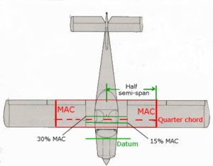 3.11.1 Maximum take-off weight Regulatory weight limits All eight recreational aviation exemption Civil Aviation Orders [CAOs] specify a limiting take-off weight or, in a few cases, a limiting empty weight. Take-off weight is the total weight of the aeroplane when it begins to taxi before taking off. The maximum allowed take-off weight [MTOW] has a number of connotations. The first is the class regulatory limit (usually 600 kg but it could be less and up to 850 kg for sailplanes) set by the CASA for recreational aeroplane operations and currently defined in the exemption orders. Those CAOs allow an individual aeroplane to be registered within a class, defined by one particular CAO sub-category, for operation not above a specified take-off weight. In addition there may be a maximum stalling speed or a maximum allowed wing loading specified in those orders. The second connotation is the structural design weight limit which is the maximum all-up take-off weight permitted by the aircraft designer, for structural safety or aircraft stability and control reasons. An aeroplane which, by design, is capable of operating safely at a greater weight than the class regulatory limit may still be able to be registered with a Recreational Aviation Administration Organisation [RAAO], provided the pilot does not operate the aeroplane at an all-up weight that exceeds the class regulatory limit — including the consequent stall speed — defined by the relevant CAO. Many small, light, composite aircraft are imported from Europe where the European Union certification standard for very light aircraft is CS-VLA (formerly JAR-VLA) with a class regulatory limit of 750 kg. These modern technology aircraft have a comparatively low empty weight and potentially high fuel capacity, so it is quite feasible to operate them as two-place 600 kg aeroplanes — provided the combined weight of the occupants is not excessive. There are other older design, two-place, light aircraft where the structural design weight limit is higher than the class regulatory limit. It may be that an RAAO might accept such an aeroplane, but these are required to carry a cockpit placard stating that the MTOW does not exceed 600 kg — or whatever the class regulatory limit might be. Because they have a comparatively high empty weight they must be operated as a single-seat aircraft so permanent removal of the passenger seat, seatbelt, passenger-side controls etc would be required to ensure operation only as a single-place aeroplane. In the type approval process, an aircraft might be assessed by a National Airworthiness Authority [NAA] to determine that the structural design weight limit is considered safe. Subsequently, the third connotation — a maximum total weight authorised [MTWA] — may apply. That MTWA may be less than the structural design weight limit and may be less than the class regulatory limit. The situation is further complicated when overseas factory-built aircraft are imported into Australia for registration with an RAAO. An example is the European countries who certify their aircraft to an European ultralight standard of 450 kg or 472.5 kg (the 22.5 kg is the addition for a parachute recovery system). If imported into Australia and registered with an RAAO, that organisation has no choice but to limit the aircraft to 450 kg or 472.5 kg MTOW even though the class regulatory limit might be 600 kg. However, if the manufacturer certifies them to another standard at a greater weight — providing that certification is accepted by a certifying body in a country that is an ICAO signatory — then an Australian RAAO can accept that higher weight, but only up to our regulatory cut-off point. Australia is an ICAO signatory and the CASA is the NAA and a certifying body. Structural design weight limit From a flight operation and safety viewpoint, the most important MTOW is the structural design weight limit, which may be less than, or greater than, the MTOW allowed under the relevant CAO. The distribution of that weight — the aircraft balance — is equally important. The structural design weight limit is related to the category of operation and the flight envelope. In the 'normal' category — applicable to all ultralights except light sport aircraft [LSA] — the structure, particularly the wing, is required to cope with minimum structural load factors of +3.8g to –1.5g. Thus, the wings of a non-aerobatic aircraft with a certificated MTOW of 600 kg is required to cater for a design limit load of 600 × 3.8 = 2280 kg plus the 50% safety factor for the ultimate load = 3420 kg. No matter which CAO class regulatory limit recreational aircraft are generically permitted to operate at, no aircraft may fly legally above the RAAO accepted MTOW for that particular aircraft type, which may not be as much as the class regulatory limit or the structural design weight limit. Payload Bear in mind that these limits relate to the structural strength of a new aircraft — and structures lose strength as they age; maybe more so if they are a very lightweight structure with little fail-safe provision. However, as aircraft age they also suffer from service weight pickup. They tend to put on weight through modifications, additional instruments or avionics, larger fuel tanks, heavier tyres and accumulation of paint and dirt — inside and outside — all of which reduce payload* capability and make it rather easy to unwittingly exceed MTOW. *In the sport and recreational aircraft context the 'payload' term encompasses the weight of the pilot, passenger(s), baggage and usable fuel. In the general aviation field, most of the privately-owned recreational tourers are single-engine, fixed-undercarriage, four-seat aircraft, like the Piper Warrior or the Cessna 172. Generally these aircraft have a MTOW around 1150 kg — comprising an empty mass which is about 55% of MTOW and a fuel capacity about 15% of MTOW; consequently, 30% of MTOW (around 345 kg) is available for carriage of the pilot, passengers and baggage. Most two-seat light and ultralight aircraft do not have a high payload capability; consequently a full fuel load — which weighs about 0.71 kg/litre — and just an average 80 kg pilot and passenger might constitute, or exceed, the maximum payload. A most important part of pre-flight planning is to ascertain the total weight of the pilot, passenger/s, baggage, tools and other cockpit gear plus fuel. It is also advisable to re-weigh the empty aircraft occasionally to re-establish the empty weight and the cg position when empty. Exceeding MTOW has consequences that increase exponentially with the excess weight: reduced structural load safety factor reduced acceleration, higher take-off speed and longer take-off distance reduced rate and angle of climb reduced cruising speed and range higher stalling speed and reduced manoeuvrability higher landing speed and extended landing distance or maybe the aircraft won't even leave the ground on take-off — which can be a bit expensive if you end up in the fence at the end of the strip. It is much more dangerous if it does get airborne but you trip over the boundary fence (see ground effect) — or if you can't establish a climb rate greater than the vertical velocity of down-flowing air at the end of the runway. If MTOW is exceeded and the cg location is outside its limits, then very dangerous longitudinal stability conditions are introduced. 3.11.2 Balance: containing cg position within limits Balance refers to the location of the cg along the longitudinal axis. Location of the cg across the lateral axis is important, but the design of practically all aircraft is such that the empty weight is generally symmetrical about the longitudinal centreline. However, the location of the cg along the longitudinal axis is both variable and critical for stability. Consequently, the cg position must be assessed by the pilot before every take-off — even if the total weight is well below design maximum safe operating weight. The lateral and longitudinal position of the cg on any flight will vary according to the weight in the pilot and passenger seats, the amount of fuel in the tank(s), the placement of any baggage and other gear, and also the weight and location of modifications and additional installed equipment since the last cg position check. (The load must be properly secured and small objects properly stowed. The last thing you need is a heavy object banging around the cockpit in turbulent conditions and damaging the canopy or something equally vital — like your head. Anything loose in the cockpit/fuselage has potential to jam the control circuits or to move rearward in the fuselage during take-off acceleration or while climbing, thus adversely affecting the cg position.) Centre of gravity range For safe aircraft operation, there must be calculated limits to the forward (nose-heavy) and the aft (tail-heavy) cg position. Those limits — measured from a datum — are specified by the manufacturer or by the amateur designer. (The datum is an imaginary vertical plane through the fuselage, possibly located at the engine firewall, the wing leading edge or perhaps the back of the spinner.) If the cg is situated between the fore and aft limits, the aircraft should have positive static longitudinal stability. Care should be taken when flying amateur-designed aircraft, as the cg range for that aircraft may not be within practical safe limits, making the aircraft dangerously unstable in some conditions. In the 'Aerofoils and wings' module it was stated that the wing aerodynamic centre [ac] is situated near 25% mean aerodynamic chord [MAC]. For longitudinal stability in light aircraft the most forward position of the cg allowable might be about 15% MAC and the most aft position about 35% MAC, basically 10% either side of the wing ac; or perhaps the aircraft neutral point. Forward cg limit — nose-heavy The forward cg limit is determined by the elevator's ability to flare the aircraft at low speed when landing in ground effect; i.e. the least forward cg position where full up-elevator will obtain sufficient moment arm to rotate to the stall aoa, without requiring the pilot to exert an excessive pull on the control column. The forward position is constrained because the further forward it is, the more download the horizontal stabiliser/elevator is required to produce to balance it. Consequently, the tailplane must fly at a greater negative aoa — thus decreasing total aircraft lift — and the wing must then fly at a greater aoa to counter the loss. This results in more drag from the wing and the tailplane and, consequently, reduced performance. The pitching moment characteristics of the wing must also be considered. If a nosewheel undercarriage aircraft is landed in a nose-heavy condition, the possibility of touching down nosewheel first — wheelbarrowing — is greatly exacerbated; a slowing aircraft, pivoting on the nosewheel, is in a grossly unstable condition. The possibility of an extreme ground loop, with consequent aircraft damage, is high. Also touching down nosewheel first can result in a bounce that is difficult to control and may end up wiping off the nosewheel gear and overturning the aircraft. If the c.g. is too far ahead, the aeroplane will continue to be stable but it could be so nose-heavy that it cannot be brought into a landing aoa, that is, it would be difficult to slow it down to landing speed. Aft cg limit — tail-heavy The aft limit is determined by the amount of reduction in the length of the horizontal stabiliser moment arm — which decreases the effectiveness of the moment — and the increase in the nose-up pitching moment of the cg/ac couple, because of the cg distance behind the ac. It is the elevator authority available at low speed that determines the aft cg limit. A cg outside the aft limit will decrease or remove longitudinal stability, and the ability to recover from stalls and spins and may itself lead to a departure stall (i.e. a stall shortly after starting to climb out from the airfield with the engine at maximum power) because there is insufficient elevator authority to lower the nose; even with the pilot applying maximum forward pressure. A go-around with the cg near the aft limit — with flaps extended, full power, and nose-up landing trim still applied — can be particularly dangerous for the unwary pilot. An aircraft does not have to be near MTOW for the fore or aft cg limits to be breached, as can be seen in weight/cg position limitations. The cg position will change as fuel is consumed. Actually, the pilot of a light aircraft can vary the cg position just by leaning forward or backward in the seat! The following is an extract from an RA-Aus incident report: "The aircraft, with instructor and student on board, was returning to the airfield when a pitch-down occurred. (Unknown to them, the elevator control horn assembly had failed.) Control stick and trim inputs failed to correct the situation, but a reduction in power did have a correcting influence, though not enough to regain level flight. A satisfactory flight condition was achieved by the pilots pushing their bodies back as far as possible and hanging their arms rearward. A successful landing at the airfield was accomplished." Mean aerodynamic chord The cg location can be expressed as a percentage of the mean aerodynamic chord [MAC], which is particularly useful for designer/builders. For a rectangular wing of constant aerofoil section dimensions, MAC is just the chord. For a symmetrically tapered wing, it is the average of the root chord and the tip chord. Further information is in 'ascertaining MAC graphically'. The position of the fore and aft cg limits is measured as a percentage of MAC, from the MAC leading edge. Usually for a single- or two-seat aircraft, the most forward position would be aft of 15% MAC and the most aft position would be forward of 30–35% MAC. Thus, the allowable cg range in a light aircraft shouldn't exceed 20% MAC. The linear distance between the fore and aft limits is perhaps 15 to 20 cm. Weight/cg position limitations To demonstrate how the weight and balance limits for a particular aircraft may vary according to the planned flight operation, I have selected a four-seat aircraft that is certificated for operation in three certification categories — normal, utility and acrobatic. The following data is extracted from the aircraft flight manual. The maximum take-off weight (in pounds) for operations in each category are: normal 2335 lb, utility 2137 lb and acrobatic 1940 lb. The fore and aft cg limits are measured in inches from the datum and also shown as a percentage of MAC. The maximum number of persons on board [POB] allowed for each condition is shown. Category Max. weight (pounds) Fwd limit (inches) % MAC Aft limit (inches) % MAC POB Normal 2335 98.19 27 103.58 36 4 Normal 1960 93.07 18.5 103.58 36 2 Utility 2137 95.47 22.5 101.77 33 3 Utility 1960 93.07 18.5 101.77 33 2 Acrobatic 1940 93.07 18.5 97.58 26 2 The table data is summarised below in graphical form, depicting the weight/cg envelope. The vertical axis depicts weight in pounds and the horizontal axis the stations in inches from the datum. The section outlined in blue is for normal operations with a +3.8g limit load factor, the green outline is for utility operations (training, spinning) with +4.4g limit and the red area is for acrobatic category operations with a +6.0g limit. To determine the fore and aft cg limits, first ascertain the weight position on the vertical scale and read across within the appropriate category. For example, with weight 2180 lb in the normal category, the forward cg limit is at 96 inches from the datum and the aft is at 103.58 inches. Note the very restricted cg and MTOW range for aerobatics — 4.51 inches (11.5 cm) or 7.5% MAC — and the requirement for the forward limit to start at 18.5% MAC, the most forward position. On the other hand, when the aircraft is at maximum normal category weight the cg range is only 5.39 inches (13.5 cm) — but now the cg range is required to be at the other end of the scale, between 27% and 36% MAC. The only occasion when the aircraft balance can be anywhere in the specified range of 18.5–36% MAC (10.51 inches or 27 cm) is when the aircraft is operating in the normal category at a weight less than 2000 lb. The area sliced off the top left corner is fairly representative of most weight/cg limitation envelopes for medium to higher-performance light aircraft. Ascertaining mean aerodynamic chord graphically For a rectangular wing of constant aerofoil dimensions and constant chord, the MAC is just the chord. For a symmetrically tapered wing it is the average of the root chord and the tip chord. The diagram below is a representation of the graphical method for calculating the MAC position on such a wing. The method works just as well for more complex wing plan forms. Note that for aerodynamic calculations the aircraft wing includes the area within or above the fuselage and the root chord is always on the fuselage centreline. The position of the wing aerodynamic centre is marked with the red asterisk. 3.11.3 Ballasting Sometimes an aircraft, with a tandem pilot/passenger seating configuration like the Breezy, will require a specified/calculated ballast weight to be strapped in an unoccupied passenger seat, unless the passenger seat is located at the cg position. There are also pusher engine designs that are entirely dependent upon sufficient minimum pilot weight to put them in balance range, so a lightweight pilot may have to sit on a ballast bag. With tandem two-seaters there will be both a minimum and maximum pilot weight for cg range, but that in turn could be influenced by rear seat weight to keep within MTOW. In some cases, the rear seat also has a moment arm and can affect the front seat arm, depending upon rear seat weight. Regulations require that any ballast, baggage or other cargo that is stowed on a passenger seat must not weigh more than 77 kg; the weight should be evenly distributed and positioned so that neither the cargo nor its restraints can interfere with the operation of the aircraft controls. In addition, if fitted with removable dual controls, the control column at the passenger seat should be removed. It is advisable that the cockpits of two-seaters — particularly tandems — but any aircraft that is dependent upon the presence of a minimum and maximum pilot weight, should be clearly placarded with the minimum/maximum seat weights shown in the flight manual. The need for ballasting is not confined to ultralights. The cg position of the four-seat Beech Sundowner is outside the forward limit when the only occupants are two above-average weight people in the front seats, and in such conditions the aircraft has a tendency to wheelbarrow on landing. Flying an unbalanced ultralight — i.e. in a tail-heavy or a nose-heavy condition — even though the cg is not outside the limits, increases pilot fatigue because of the need to maintain a constant heavy pressure on the control column if no trim device, or a limited device, is fitted. 3.11.4 Calculating cg position and moment Unloaded aircraft The longitudinal position of the cg and its moment about a datum are readily calculated. A measuring tape, heavy-duty bathroom scales, plumb bob and a chalk line are needed. The following is the procedure for an empty light nosewheel aircraft. Chalk a straight line on a level surface that is at least the length of the fuselage, then chalk another line perpendicular to that. Roll the aircraft along the longitudinal line until the axles of both main wheels are directly over the cross line. Chalk another short cross line to mark the nosewheel axle position. Mark a position on the longitudinal line that is directly below the front or back end of the spinner thus providing a datum. Measure the longitudinal distance (the nosewheel moment arm) from the datum to the nosewheel axle line and the distance (the mainwheel moment arm) from the datum to the main wheels axle line. Place the scales under the nosewheel, block up the mainwheels so that the aircraft remains level and note the weight. Then place the scales under one of the mainwheels and block up the other main plus the nosewheel. Note that weight. Repeat for the other mainwheel. Add the weight on the nosewheel to arrive at the aircraft empty weight (or perhaps its weight with full fuel). Multiply the nosewheel weight by its arm to get the nosewheel moment and the added mainwheel weights by the axle arm to get the mainwheel moment. Add the two together to arrive at the total empty aircraft moment. The cg location from the datum equals the empty aircraft moment divided by the total aircraft weight. For example: Nosewheel weight = 80 kg and arm = 0.5 m Thus nosewheel moment = 40 Mainwheel weight = 2×160 kg and arm = 2.5 m Thus mainwheels moment = 800 Empty aircraft weight = 80+160+160 = 400 kg Empty aircraft moment about the datum = 40 + 800 = 840 Cg location when empty = 840/400 = 2.1 m from the datum Loaded aircraft The cg location with pilot/passenger aboard can be calculated if a point about 20 cm forward of the seat back (being the approximate centre of mass position of a seated occupant) is marked on the longitudinal chalk line; the distance from the datum to that point is the front seat(s) moment arm. The front seat(s) moment is the occupant(s) weight multiplied by the arm, and the new cg location is the empty aircraft moment plus the front seat moment divided by the empty aircraft weight plus occupant weight. For example: Side-by-side front seats arm = 2.3 m Occupants weight = 150 kg Thus front seats moment = 345 Empty aircraft weight = 400 kg Empty aircraft moment = 840 Total aircraft weight = 550 kg Total aircraft moment = 1145 cg location = 1345/550 = 2.08 m from the datum Similar calculations can be made to include fuel weight and baggage distribution and weight. Aircraft or kit manufacturers should provide data defining a datum together with the associated arms for the pilot/passenger seats, fuel tanks and baggage compartments, plus the fore and aft cg limits expressed as a distance from the datum. With such information the pilot can calculate the loaded cg position using the measured weights of occupants, fuel and baggage. The aircraft manufacturer should provide a loading chart to facilitate calculations. Of course the manufacturer's chart is useless (and you may make the aircraft dangerously unstable) if you stuff baggage and equipment into any available space outside the designated and designed baggage compartment. STRICT COPYRIGHT JOHN BRANDON AND RECREATIONAL FLYING (.com)
 -
 3.10.1 Control in pitch In section 6.3 we learned that movement of the elevators provides a pitching moment about the lateral axis, that initiates a change in the aoa. Once the new aoa is established, then — provided the elevators are held in that deflected position by pilot pressure on the control column or a trim device — the pitch moment returns to zero and the aircraft maintains that aoa (and there is a direct relationship between aoa and IAS). In the manoeuvring forces module we established that aoa and power combinations provide (a) increased speed or climb and (b) decreased speed or descent — or varying degrees of either. Thus, control in pitch (i.e. of aoa) combined with throttle control allows an aircraft to take-off, climb, cruise at various speeds, descend and land. However, control in pitch involves more than initiating a discrete pitching moment to effect an aoa change and subsequent attitude change. In section 1.10 we found that to sustain a turn, an additional force must be continuously applied towards the centre of the curve or arc — the centripetal force. This is achieved by an increased aoa — greater than the normal for a particular straight and level airspeed — held with control column back-pressure. The increased aoa provides the centripetal force, and that force keeps the aircraft constantly pitching 'up' in the longitudinal plane, into the direction of turn. 3.10.2 Control in yaw Aircraft perform much better if their longitudinal axis is accurately aligned, in plan view, with the flight path; i.e. with the relative airflow. Also, an aircraft flying with a constant angle of slip is part way to ending up in an unusual flight attitude. Thus, the primary task of the fin and rudder combination is to act as a stability and trim device so that the directional stability system will restore flight to the proper state of zero sideslip angle. If the rudder has no trim tab, as would be the case with most light aircraft, then the pilot would have to keep the aircraft in trim by applying pressure to one rudder pedal. This pressure will vary with airspeed and the sideslip angle. This trimming task also includes the use of rudder to overcome adverse yaw when initiating a turn, and to keep the turn balanced or 'coordinated'. The very simple flight instrument provided to indicate slip — or skid in a non-coordinated turn — is the balance ball. A metal ball is enclosed in a short, transparent, slightly curved tube where movement is somewhat damped by the restriction of the tube. When the aircraft is flying with zero sideslip, the ball will be centred at the bottom of the curve; when the aircraft is slipping into (or skidding out of) the turn, the inertial forces will move the ball left or right in the direction of the slip. To trim the aircraft, the pilot applies pressure on the rudder pedal on the side to which the ball has moved; i.e. 'steps on the ball'. When the aircraft is slipping, the pilot will also feel those inertial forces apparently pushing his/her weight in the same direction as the ball, hence the expression 'flying by the seat of your pants'. The amount of pilot-induced yaw, at a given airspeed, is dependent on the degree of rudder deflection. If the pilot holds the rudder deflection, the aircraft will continue yawing and sideslipping. But, as the aircraft rotates about the normal axis, the wing on the outside of the rotation must be moving a little faster — and the inner wing a little slower — so there will be a small lift differential. The differing lift moments will raise the outer wing and lower the inner wing and the aircraft will enter a banked turn. A pilot would not initiate a sustained turn by using rudder alone, but there are occasions when it is appropriate and effective to alter the aircraft's heading a few degrees by using just rudder — or perhaps rudder plus a little opposite aileron to stop the bank. Such occasions are when finally aligning the aircraft with the runway centre-line or compensating for small changes in wind direction when landing. We will cover this in the 'Circuit, approach and landing' module. Having said that, there is still an occasion where a rapid 180° change in direction is achieved solely with rudder; see the following. The ultimate use of rudder to yaw the aircraft is demonstrated when the pilot of an aerobatic aircraft executes a 'stall turn' or 'hammerhead'. The former term is perhaps a misnomer, because the wing does not reach the critical aoa during the manoeuvre. The manoeuvre involves pulling the aircraft into a full-power vertical climb then, as the airspeed decays to somewhere near the normal stall speed, applying full rudder so that the aircraft is yawed 180°, about the normal axis, into a vertical descent. The slipstream supplies the energy to the rudder for the turn. The interesting thing is that, although the aircraft is at or below normal stall speed, the wings are nowhere near the critical aoa as, towards the end of the climb, the control column is held forward of the neutral position — and because of the low aoa and low V², the wings are not producing much aerodynamic force*. The length of the vertical 'up-line' depends on the aircraft's power/weight ratio — and thrust power and momentum are reducing quickly. Of course, if the pilot delays too long before applying full rudder, the weight vector will take over and cause the aircraft to slide vertically backwards — a tailslide. *In fact the wing could be at the 'zero lift' aoa where the aerodynamic forces on both sides of the wing are equal and opposite. 3.10.3 Control in roll We discussed how ailerons produce a rolling moment in section 4.10, so what happens when the ailerons are normally deflected, by the pilot moving the control column to the left or right? Initially the aircraft will start to roll, and if the control column is then returned to the neutral position the roll will cease but the bank angle reached will tend to remain. To level the wings, the column has to be moved to the opposite side — then returned to neutral once the wings are again level. Which indicates there always tends to be a sort of 'neutral stability' in the lateral plane. However, that situation doesn't exist because, as we found in section 7.4, other forces come into play when the aircraft is banked — creating sideslip, then yaw and eventually a turn. So the prime reason for introducing a roll is as the first step in turning. However, before going on to the turn, let's just look a little further at the effect of aileron deflection while elevator and rudder are held in the neutral position, when the aircraft's velocity is high; i.e. pure roll. The simplest aerobatic manoeuvre is the aileron roll, which (in aircraft that have been certificated for aerobatics) is usually accomplished by first gaining some extra kinetic energy, applying full power and raising the nose so that it is pointing 20° or so above the horizon with the balance ball centred. The control column is then firmly moved left or right to the full extent of travel and held there, while the elevators and rudder are both held in the neutral position; i.e. the roll is produced solely by the aileron deflection. The aircraft will then continue to roll about its longitudinal axis — because the ailerons being positioned towards the wingtips produce a strong rolling moment about the axis — more or less at a steady rate of roll, until the accumulated extra energy is exhausted. If the column was not moved to its full extent, the aircraft will still roll, but the rate of roll will be slower yet still steady. The time to complete a full 360° roll is very much dependent on the aircraft design and that roll rate dictates how many complete rolls can be produced before the aircraft ends up with the nose pointed well below the horizon — because of the combined effects of slip, yaw and the full 360° inclination of the lift vector. The rate of roll for a competition-class aerobatic aircraft is around 360° per second; for the more mundane aerobatic aircraft, it is around 60° per second, which will probably produce only one full 360° roll. A properly executed roll will result in a continuing 1g load throughout the manoeuvre. 3.10.4 Control in a turn We come then to the question 'how do you turn an aircraft?' Well, you can make the aircraft's nose turn just a few degrees without banking by just applying pressure on the rudder pedal in the direction you want the nose to move and at the same time moving the control column a little sideways in the opposite direction to stop the consequent bank. Applying pressure to the rudder in one direction with opposite aileron is cross-controlling. Normally, this is a very sloppy way to fly but also a habit that can lead to trouble — particularly in low-speed descending turns, such as that made in the approach to landing. Although not directly related to turns, this extract from an RA-Aus incident report illustrates how easy it is to get into difficulties if you don't realise you are cross-controlled at low speeds. "The student had completed two solo circuits and landings without incident. During the third the landing appeared normal, the aircraft touched down without bouncing but then veered left and the left wing lifted. The student applied full power but the aircraft failed to climb normally and appeared to be staggering and slowly orbiting to the left. The aircraft only gained about 40 feet height then gradually descended, striking the ground nose low and left wing low. The student was not injured. It was found that he had maintained full left rudder when he applied full power and was using aileron to counter the yaw — the aircraft basically sideslipped into the ground." The normally recommended way to initiate a level turn (to the left) is to move the control column to the left until the required bank angle is achieved, then return the control column to neutral. At the same time as applying aileron, just sufficient bottom (left) rudder is applied to balance the turn so that there is no slip or skid and the balance ball stays centred. Also, the amount of rudder required increases as airspeed decreases. As the aircraft banks, the lift vector departs from the vertical, so the aoa must be increased sufficiently that the vertical component of lift always exactly balances weight. This means increasing back-pressure on the control column as bank is applied. As aoa increases, induced drag increases. So, to maintain V² throughout the turn, power must be increased. Thus a properly balanced, constant rate and constant-speed turn implies a smoothly coordinated application of aileron, rudder, elevator and power. In some aircraft, particularly slower aircraft with high aspect ratio wings, it is necessary to lead the turn with quite a bit of rudder (because of aileron drag) before adding aileron. In other aircraft it is quite easy to initiate and continue a turn without using rudder at all, but the turn will be uncoordinated — i.e. the balance ball not centred — and such conditions are not desirable. During a banked level turn, the outer wing is moving very slightly faster than the inner wing and will consequently produce more lift; the bank will tend to increase and the turn to wrap-up even though the ailerons are in the neutral position. In order to maintain the required bank angle it is necessary to apply a slight opposite pressure to the control column, which is known as 'holding off bank'. This is relative to level and climbing turns, but different physics apply to descending turns. In a climbing turn, the outer wing has a slightly greater aoa than the inner wing, and thus additional lift. Combined with its slightly faster speed, this reinforces the tendency for the bank angle to increase and the need to hold off bank. The reason for the higher aoa of the outer wing is because of a difference in relative airflow. Imagine an aircraft doing one complete rotation of a continuing climbing turn. Obviously all points on the airframe are going to take the same time to achieve the higher altitude; however, the upward spiral path followed by the outer wingtip must have a larger radius than that followed by the inner, and therefore the path followed by the outer wingtip is not as steep as that followed by the inner. The less steep path of the outer wing (i.e. the relative airflow) means that the aoa of the outer wing will be greater than that of the inner. You might have to think about it a bit! The reverse occurs in a descending turn — the steeper path of the inner wing in the downward spiral means that it will have a larger aoa than the outer wing, which may compensate, or overcompensate, for the faster velocity of the outer wing. In order then to maintain the required bank angle it is necessary to apply an inward pressure to the control column; i.e. in a descending turn the bank must be 'held on'. If the pilot tends to hold off bank in such a turn, there will be an excess of 'bottom' rudder and the aircraft must be skidding. Whenever an aircraft is slipping or skidding, the wing on the side to which the rudder is deflected will stall before the other, with a consequent instantaneous roll in that direction. So the situation we've described — holding off bank in the descending turn with excess bottom rudder — means that should the aircraft inadvertently stall — a cross-controlled stall — it is going to roll further into the bank and enter an incipient spin. Hence the old adage — 'never hold off bank in a gliding turn'. A cross-controlled stall typically occurs in the turn onto final approach for landing. If you must fly cross-controlled when banked, then it is better to fly with an excess of top rudder, as in the sideslip manoeuvre. Thus, if the aircraft should stall, the roll will be in the direction of the upper wing; i.e. towards an upright position. And never apply an excess of bottom rudder in an attempt to tighten any turn, particularly when the airspeed is low for the bank angle employed and/or height is low. This is discussed further in the 'Safety: control loss in turns' module. A breaking turn is a defensive flying manoeuvre, which every pilot should be able to perform rapidly and automatically to avoid collision, particularly in the circuit. It involves very rapid transition, usually into a steep descending turn, but a steep climbing turn may be necessary. A level turn is an unlikely choice, but whatever turn is chosen you must be able to perform it instinctively while your head is continually swivelling to ascertain the location of other aircraft — without falling out of the sky by inadvertently applying back-pressure on the control column and thus exceeding the critical aoa. Before we go on to the sideslip, another very simple aerodynamic demonstration — but only for aerobatic aircraft whose engine and airframe are able to take the loads, and absolutely never for any other aircraft — is the flick roll. The flick or snap roll asymmetric aerobatic manoeuvre is an accelerated stall combining a rapid increase in aoa with a full yaw. It is brought about — when cruising straight and level at a speed less than Va — by pulling the control column firmly back as far as it will go while applying full left or right rudder. The wing in the direction of the applied rudder stalls first and the aircraft flicks into a 360°, roughly horizontal, roll. The roll will continue while the rudder and elevators are held at their limits (and cease when they are returned to the neutral position) but the aerodynamic drag produced by the manoeuvre slows the aircraft quite rapidly and the aircraft will enter a vertical spin if the roll is held too long. The faster the entry speed, the higher the torsional stress on the rear fuselage and empennage, the engine mountings and perhaps even the engine crankshaft; but the slower the speed, the greater the likelihood of immediately entering a spin, and recovery technique is dependent on several variables. The roll is usually a lot snappier in the opposite direction to propeller rotation. Flick rolls may be executed only in aerobatic aircraft designed to withstand the extreme stresses. Such a simple control action, whether or not while turning, demonstrates how easily misuse of rudder can end up in an unusual and dangerous attitude, and where the possibilities increase as speed decreases. And be aware that you don't have to actually push on the rudder pedal, you can easily achieve misuse by inadvertently slipping one foot off the rudder bar at a critical time — the turn onto 'final approach' for example. 3.10.5 Sideslip as a manoeuvre Types of sideslip vary in degree — from inadvertently flying cross-controlled in the cruise (i.e. one wing slightly low and compensating with opposite rudder) to a fully-fledged cross-controlled turn where the aircraft is steeply banked in a descending turn with full opposite rudder applied. All sideslips reflect uncoordinated flight and result in increased drag. Note: in aerodynamic terms, any time it is evident that the aircraft's longitudinal axis is at an angle to its flight path (in plan view) then the aircraft is sideslipping (i.e. its motion has a lateral component), and the angle between the flight path and the axis is the sideslip angle. Aerodynamicists don't generally distinguish between sideslip and 'slip' or 'skid', but many pilots use 'slip' as the general term, 'skid' to describe slipping away from the centre of a turn and 'sideslip' to describe a particular type of height-loss manoeuvre. The sideslipping manoeuvre is only for the pilot who has a very good feel for their aircraft because, among other things, the ASI will most likely be providing a false airspeed indication. High sideslip angles combined with high aoa must be avoided. There seem to be as many definitions of the types of slip as there are exponents of sideslip techniques, but the safe execution of all sideslips requires adequate instruction and continuing practice. Here are some types: The straight or steady-state sideslip approach to landing The helmet and goggles crowd who, very sensibly, like to fly biplanes and other open-cockpit aircraft not equipped with flaps, need a manoeuvre for use on the landing approach to a short strip that enables them to lose height quickly without increasing airspeed and which provides a good view of the landing area. The answer has long been the cross-controlled steady state sideslip; a manoeuvre designed to lose height over a short distance, dumping the potential energy of height by converting it to drag turbulence rather than kinetic energy. Such sideslips may also be a requirement when executing a forced landing, and the same type of slipping approach may also be necessary for those aircraft where, in a normal approach, the pilot's view of the runway is obstructed by the nose. Once established on the approach descent path at the correct airspeed, the aircraft is banked with sufficient opposite (top) rudder applied to stop the directional stability yawing the nose into the relative airflow and thus turning. Slight additional backward pressure on the control column may be needed to keep the nose from dropping too far. The aircraft sideslips in a moderate to steep bank with the fuselage angled across the flight path, giving the pilot a very good view of the landing area. The greatly increased drag, from the exposure of the fuselage side or 'keel' surfaces to the oncoming airflow, enables an increased angle of descent without an increase in the approach airspeed. The execution of a sideslip to a landing varies from aircraft to aircraft and it may not work particularly well where there is a lack of keel surface — an open-frame aircraft like the Breezy, for example. The sink rate is controlled by aileron and power is held constant, usually at idle/low power, and the sideslip must be eased off before the flare and touchdown. When recovering, care must be taken to coordinate relaxation of the back-pressure, leveling of the wings and straightening of the rudder — otherwise the aircraft may do its own thing or stall, particularly in turbulent conditions. The straight sideslip is limited by the maximum rudder authority available; there will be a bank angle beyond which full opposite rudder will not stop the aircraft from turning. Although this manoeuvre usually comes under the proprietorship of the 'stick and rudder' people, the use of the sideslip, by the captain of a Boeing 767, undoubtedly saved the lives of many people in an extraordinary incident that occurred in 1983 when, due to a train of errors — as are most accidents/incidents — an Air Canada 767 ran out of fuel at 41 000 feet. The captain subsequently glided the aircraft to a safe landing on an out-of-service runway, which was being used for a drag racing event at the time. The aircraft was sideslipped through several thousand feet to lose excess height on the approach. For more information about this magnificent demonstration of airmanship (following an execrable demonstration of preflight procedure by many people; keep the old adage in mind — "proper pre-flight procedure precludes poor performance"!) google the phrase 'Gimli glider'. The sideslipping turn Slipping whilst turning is a manoeuvre often used in non-flap equipped aerobatic aircraft where it is desirable to perform a curving landing approach. This is also a useful emergency manoeuvre if it is necessary to increase the sink rate during a turn — such as the turn onto final approach in a forced landing when an overshoot of the landing site is apparent. It is just a sideslip where insufficient top rudder is applied to stop the aircraft turning while slipping. The rate of turn and the rate of sink are controlled by the amount of bank and the amount of rudder but it is an uncoordinated descending turn. Dangerously high descent rates are achieved if the bank angle applied exceeds the full rudder authority. Fishtailing Fishtailing is a series of sideslips where the wings are held level in the approach attitude with (alternating) aileron while the aircraft is repeatedly yawed from side to side by applying alternate rudder; the increased drag increases the sink rate and is possibly used as an emergency measure if overshooting a forced landing. The manoeuvre is generally not recommended, because uncoordinated control use at low levels may lead to dangerous loss of control. Also, excessive alternating rudder reversals may overstress the fin/rear fuselage. Sideslip to a crosswind landing In a sideslip to a crosswind landing, the aircraft is always banked with the into-wind wing down so that the sideslip can be smoothly decreased to a forward slip (below) before the roundout. Most aircraft tend to be slower in the slip, so the nose will need to be a bit lower than that needed to maintain the normal approach speed. A smoothly executed sideslip approach requires much practice, but displays considerable finesse to a ground observer. The forward slip crosswind approach A 'forward' slip is a moderate sideslip application designed only to compensate for crosswind during approach and landing. The slip can be applied throughout the final approach or just in the last stages, and it usually follows a full sideslip approach in crosswind conditions. The into-wind wing is lowered with sufficient bank so that the slip is exactly negating the crosswind drift, while opposite (top) rudder is applied to stop a turn developing and to align the aircraft's longitudinal axis with the flight path — and the runway centreline. If drifting off the path, just add or remove some aileron pressure and, at the same time, add or remove some rudder pressure to maintain direction. An approach speed 2–3 knots above normal is set up, the sink rate (which will be greater than usual because of the inclined lift vector) is controlled by the power setting, the into-wind main landing gear will touch down first and the aircraft is held straight with rudder by pivoting on that one wheel until ground speed has reduced to a safe level. The forward slip is the particularly recommended technique for crosswind landings in high-wing taildragger aircraft. Incidently, a useful technique for a high-wing taildragger in a significant crosswind is to also perform the take-off run on one main wheel. If there is any real difference between the straight sideslip and the forward slip it is just the amount of pressure applied to the controls. In a sideslip, the aileron pressure dictates the angle of descent and the rudder pressure dictates the amount the fuselage is deflected across the flight path. In a forward slip, the aileron pressure is just enough to compensate for the crosswind drift and thus maintain position on the extended runway line, and the rudder pressure just enough to keep the fuselage aligned with both the landing path and the flight path. There is one manoeuvre for certified aerobatic aircraft that demonstrates what might be considered a reversal of all we have stated in this module. This is the 'four-point slow roll' or 'hesitation roll' where the aircraft is rolled through 360° in level flight around a point on the horizon, but the roll is paused for a second or two at each 90° point; i.e. when the wings are first vertical, when the aircraft is upside down, when the wings are again vertical and when the aircraft returns to normal attitude. The roll is started (to the left) with normal aileron and a bit of left rudder, then as the roll progresses through the first 90° top (right) rudder is increasingly applied to negate the yaw, and also to hold the nose up. During the slight pause at the 90° position the aircraft is being held in a nose-up attitude by the rudder whilst the elevators are used to stop the nose wandering to the left or right across the horizon, and the ailerons are neutral. Some lift will be generated by the fuselage having an aoa because the nose is being held up. Then the roll is restarted until, at the 180° position, the aircraft is inverted and the nose is held up by a large forward movement of the control column and the aoa is negative; i.e. the lift is being generated by a reversed aerofoil. And so the roll continues. Of course, all the control movements involve gradual increase/decrease in pressures throughout the sequence. 3.10.6 Spins The 'stall/spin' phenomenon When an aircraft is held in a turn, and near the critical aoa with excess bottom rudder applied (i.e. a cross-controlled skidding turn, which often happens when the pilot tries to 'hurry' the turn with bottom/inside rudder instead of increasing bank) the lower, partly blanketed, wing will be producing less lift than the upper wing. Any tightening of back-pressure on the control column (or any inadvertent back-pressure applied when, for instance, looking over your shoulder; or even any encountered turbulence or wind shear) may take the aoa past the critical angle. The lower wing will drop sharply in an 'uncommanded' roll, and thus become more deeply stalled than the upgoing wing — which may not be stalled or just partly stalled. The high aoa of the lower wing causes greatly increased induced drag, yawing forces in the same direction as the lower wing come into action, the nose swings down and the aircraft enters an incipient (i.e. partly developed) spin condition, where it is about to start autorotation (below). All of this happens quickly, and in some aircraft very quickly indeed. If the aircraft is properly weight-balanced (i.e. weight less than MTOW and cg within the defined fore and aft limits), this is readily countered by quickly easing stick back-pressure to reduce aoa below critical aoa — which immediately restores full control — applying sufficient rudder to stop further yaw, adding full power and rolling the wings level with aileron while keeping the balance ball centred. However, if the slew, exacerbated by the yaw, is allowed to develop past perhaps a 45° movement in azimuth, then there is a stall/spin situation. You sometimes hear about this when an unaware pilot allows such to develop close to the ground — often when performing a climbing turn after departure from an airfield; or in a turn-back to the runway following engine failure after take-off; or when in the descending turn from base leg on to the final approach to landing where, because of illusory ground reference cues, there may be a tendency to increase the rate of turn by applying additional bottom rudder whilst maintaining the bank angle with opposite aileron — 'holding off bank' as mentioned in section 8.4. Ultralights, with their very low wing loading, normally display quite benign stall characteristics when slowly decelerated to stall speed in straight and level flight. But they may exhibit quite nasty behaviour in an accelerated stall or when a stall is initiated during a turn; and such are the usual unintentional stall/spin modes. Under these circumstances the height lost in the incipient spin — the initial entry to autorotation — may be 100 to 400 feet. Thus, an incipient spin condition is highly dangerous when occurring in the circuit pattern or in any other low-level flight situation. See the flick roll box above and read the sections dealing with 'limiting climbing turns during take-off' and 'accelerated stalls'. There may be uncertified light aircraft where characteristics, such as rolling inverted in a relatively mild stall/incipient spin situation, are evident. However, a commercially manufactured aircraft with such characteristics should not receive a CASA Certificate of Type Approval. Autorotation — the fully developed spin With adequate training, an incipient spin is readily anticipated and easy to correct — provided the aircraft weight and balance are within the stated limits. But, if the correction is not done before the nose has swung maybe 90° or so, it may develop into autorotation where the aircraft is descending in a stabilised, usually nose-down, rotation — rolling and yawing in the same direction at a constant airspeed at or slightly above Vs1 — a full-blown spin with each 360° rotation taking only 2–4 seconds in a very light aircraft. The height loss during each rotation — 200 to 400 feet or more, depending on the stall speed and the steepness of the spin — plus the considerable height loss during the pull-out from the recovery dive, is insignificant at a reasonable height but will be critical at lower levels. In a normal turn the aircraft's longitudinal axis is more or less aligned along the flight path — which is the periphery of the turn — the cg moves along the flight path and the inner wing is pointing towards the centre of the turn. But in fully developed autorotation the vertical axis of the spin is located somewhere in the 90° sector between the lateral and longitudinal axes and not so far from the aircraft's cg — perhaps less than two fuselage lengths. Thus, the aircraft is not turning in the normally accepted meaning of the word; it is 'spinning' around that vertical axis, while it's also rolling and yawing about the aircraft's cg; and also pitching somewhat. The lower wing is more deeply stalled than the higher producing less lift but, being on the back slope of the CL curve, more induced drag so providing the asymmetrical yawing and rolling moments. Those aerodynamic forces produced by the wings drive the spin while the resistance of the rear fuselage and empennage reaches a point where it prevents the yaw from developing further; the aircraft's inertia resists change in angular momentum so producing the stable autorotation condition. Usually the structural loads are only a little above normal during autorotation. In a steep spin, the nose is pitched down perhaps 50–60°, the aoa of the lower wing is 20–30°, there is a fair bit of bank and the roll motion dominates. The spin axis will be perhaps somewhere near one or two fuselage lengths forward (more or less) of the aircraft's cg — further away for a steeper spin. The cg will be following a helical flight path. In a flat spin, the nose is pitched down perhaps 10–20°, with an aoa around 60–70° due to the high vertical component of the relative airflow. With very high induced drag and little bank, the angular rotation winds up and yaw motion dominates. The spin axis will be much closer to the aircraft's cg, perhaps even within the airframe, and particularly so if the cg is in an aft position. The closer the spin axis is to the cg, the harder it is to break out of the spin. If the axis coincided with the cg, break-out would be impossible — unless the aircraft was equipped with a ballistic parachute recovery system. Most very light tractor-engined aircraft spin steeply to moderately steeply, so spin recovery early in autorotation is usually — but not always — straightforward: close the throttle, ailerons to neutral, stop the yaw (by applying full rudder opposite to the rotation direction apparent through the windscreen or shown by the turn indicator (not the balance ball/needle), then unstall the wings to stop the spinning (generally by applying full forward stick rather than just moving it to or past the neutral position until the spin stops). Control movements must be carefully sequenced and positive. The aircraft will be in a steep descent when the spin has ceased; the aerodynamic loads during the subsequent pull-out from the descent may lead to an accelerated stall if the aircraft is nearing the surface and the pilot applies extreme back-pressure. The height loss just during the pull-out stage may exceed 400 feet, so that the total loss of height during spin entry and recovery could easily exceed 1000 feet. The problem for a pilot who is conscious of the need to avoid stall conditions when in the circuit by always maintaining a safe speed near the ground, and has had ample training in stall and incipient spin recognition and recovery, occurs when a spin is inadvertently induced at altitude. If that pilot has never previously encountered full autorotation then the disorientation associated with the first experience can be frightening. The pilot may also experience a ground rush illusion where the surface features rapidly spread out to fill the entire field of view and the ground appears to rapidly rise; the reaction is to freeze or to pull back on the control column, which just ensures that the aircraft is held in the stalled condition even though there may be ample height available to recover. The photo at left was taken about 1949 and shows what happened when a student pilot got himself into a spin, evidently retained back-pressure on the control column and allowed the Tiger Moth to spin all the way to the ground from above 2000 feet. The spin developed into a flat spin, with relatively low vertical and horizontal speed, enabling the pilot to walk away with minor injuries. Also the Tiger Moth had a tough steel tubing fuselage frame, which absorbed much of the impact energy. You can see that the fuselage aft of the engine compartment firewall seems practically undamaged. The pilot of any aircraft will not be exposed to the risk of an unintentional stall/spin if they always remain situationally aware, maintain an appropriate energy balance, does not indulge in very low-level manoeuvring and, above all, flies the aircraft. Don't practice stalling below 3000 feet agl; and remember spins result from a loss of lateral and directional stability at the critical aoa, and the only way to get into a spin is to first exceed the critical aoa. Also, sufficient forward stick movement will immediately decrease aoa below the stall angle and restore full control in any stall or near-stall condition; but not in autorotation where opposite rudder and full forward control column movement is necessary because (1) the aoa developed will be well past the critical aoa and (2) the control surfaces will not be as effective as usual — the fin and rudder could be screened by the tailplane and thus in a low energy, turbulent airstream. Intentional spinning Stall/spin events occurring at a safe altitude are insignificant; they may become nasty accidents when they occur at lower levels. But intentional spins can be fun in an aerobatic aircraft that has been certificated for intentional spinning and, given sufficient height, quite easy to recover from — provided the cg position is within the forward and aft limits. The challenge is in aiming for a precise number of turns, half-turns or quarter-turns and the exact direction the aircraft will be heading at recovery. Spin characteristics are very complex and vary greatly between aircraft. Generally the intentional spin is induced from level flight by closing the throttle, bringing the aircraft to the point of stall in a nose-up attitude, holding ailerons in the neutral position then applying full rudder in the direction you want the aircraft to rotate and, at the same time, pulling the stick right back. Hold the neutral aileron, full rudder and back stick. The reason for the excessive control movements is to ensure a swift and definite entry into autorotation. The higher the nose is held above the horizon at the point of stall the more violent will be the spin entry. Aircraft that tend to spin with the nose pitched well down will recover more quickly than aircraft where the spin attitude is relatively flat. However, if allowed to continue past two or three full turns, then centrifugal forces become well established — which tend to make all parts of the aircraft rotate in the same horizontal plane. Then, a nose-down spin may turn into a flat spin, which will then speed up rotationally, the rate of descent decreases, spin radius decreases and break-out will take longer, or may not be possible because it may be impossible to lower the nose. The spin axis may be very close to the pilot which would be very disconcerting. Recovery control forces required usually increase as the spin winds up; also, after initiating recovery action, the spin may increase a little before the action takes effect. Engine power — and its associated effects — also tends to flatten the spin. The flatter the spin, the closer the spin axis is to the cg and the greater the aoa, maybe 75° or more! Also, at such angles, the rudder may be completely blanketed by the fuselage/tailplane, making that control quite ineffective. Structural stresses increase as the spin progresses. A flat spin might be induced if, at the point of stall, full opposite aileron is applied with full rudder. If an aircraft stalls when inverted, it may enter an inverted spin if the control column position was held well ahead of neutral at the stall. It only happens during aerobatic routines — such as a poorly executed entry into a half-roll off the top of a loop, or messing up a stall turn. The recovery from an inverted spin involves correcting the yaw and increasing stick back-pressure until rotation ceases, then rolling level when speed has increased sufficiently; but the great danger in an inverted spin is pilot disorientation. One thing is certain — NEVER, NEVER intentionally spin an aircraft that has not been through the complete spin certification process; they may be incapable of recovery from fully developed autorotation, or the recovery attempt may result in a violent manoeuvre that overloads the airframe. Spin restrictions are not confined to non-aerobatic aircraft; for example, intentional spins were prohibited in the Seafire 47 and Sea Fury, very fast naval fighters of the late 1940s early 1950s, because of the time to recover (if recovery was possible) and the consequent extreme height loss. Spin recovery confidence building Developed spin recovery training is not included in the RA-Aus Pilot Certificate syllabus or the General Aviation Private Pilot Licence syllabus, but stall and incipient spin awareness and recovery are normal parts of the syllabi. A spin is usually classified as an aerobatic manoeuvre and, as all RA-Aus registered aircraft are prohibited from such manoeuvres, they shall not be allowed to enter an intentional developed spin. More to the point, no ultralight (and rather few light non-aerobatic aircraft) has ever been through the complete flight test schedule for spin recovery. However, gaining some experience and confidence in recovery from full autorotation can be readily and cheaply obtained by practicing a half-dozen spin recoveries with an instructor in a two-seat glider or powered aerobatic GA aircraft. It is probably better experience in the glider, as you are also exposed to the fact that every glider landing is achieved easily without using any chemical energy; on the other hand, a GA aircraft provides more opportunity to also explore the basic aerobatic manoeuvres — rolls, loops and stall turns. Incidently, 30 minutes thermalling in a glider will also demonstrate the absolute need to coordinate rudder and aileron in every turn — the ailerons on the long slender wings provide a large adverse yaw moment. These intentional spins should not be made from level flight, as described above, but should be made from those flight situations where unintentional spins are most likely to occur; i.e. in climbing and descending turns. These defensive flying lessons will also expose the student to the fact that it is very easy to invoke an accelerated stall during the pull-out after breaking out of the spin, if excessive control column back-pressure is applied — which is an automatic reaction if the ground is rising up to smite you! Spin recovery training in a spin-certified aircraft does invoke a recognition of the behaviour of that aircraft type immediately prior to an incipient spin event, but these warning signs will vary between aircraft types — or even aircraft of the same type. However, knowing how to recover from a stall/spin situation is of no help if it develops at a height that does not provide sufficient height for recovery — circuit height, for example. At such heights the aircraft must always be operated at a safe airspeed (1.5 × Vs1) and restricted to gentle manoeuvres. The 'falling leaf' manoeuvre During World War I, a very simple manoeuvre called the 'falling leaf' was developed as an incipient spin training exercise consisting of repeated entries into incipient spins while the ailerons are held in the neutral position. Although simple, the exercise requires precise timing — so that speed remains at and just above stall — and a good 'feel' on the controls plus very good 'hands and feet' coordination. It involves the initiation of an incipient spin by bringing the aircraft to the point of stall in level flight, then pulling back on the control column whilst applying full rudder. As the wing drops, the control column is moved forward to the neutral position to unstall the wings, then opposite rudder is applied and held, which actions stop the yaw and the incipient spin. Then the control column is pulled back again to stall the wings whilst the rudder is held in the same position; thus an opposite-direction incipient spin is started. Those sequences are repeated so that as the aircraft mushes down, in and out of the stalled condition, it slips from side to side in a series of small arcs, supposedly as a falling leaf may descend. Nowadays the falling leaf is classified as an aerobatic manoeuvre, thus performing the exercise in an ultralight is prohibited. Obviously before any falling leaf exercise is attempted the pilot must receive appropriate spin recovery training. The falling leaf term is also used to describe the technique of 'walking or pedalling down' a stalled aircraft by picking up a dropping wing with opposite rudder and then leaving the rudder applied a little longer than necessary so that the other wing starts to drop. In the latter technique, which is also a good developmental exercise in smooth air, the aircraft shouldn't be allowed to display much lateral movement during the descent. One of Bob Hoover's popular airshow demonstrations, the 'Tennessee Waltz', is a graceful falling leaf manoeuvre. Again, this exercise should not be attempted unless the pilot has appropriate spin recovery training — and ample height because of the substantial height loss in all falling leaf manoeuvres — but all these types of control exercises do provide an excellent means of familiarising yourself with the feel of your aircraft at low speed and its particular stability foibles. Picking up a dropping wing with rudder There is occasionally some debate about the merits of using the secondary effect of rudder to pick up a dropping wing when flying at or near the stall. The dropping wing has not been arrested by roll stability because it is partly or fully stalled. (The reason for proposing use of rudder rather than aileron is because if the dropping wing is near the critical angle of attack the use of aileron will increase the camber of that section of the wing taking it into, or further into, the reducing lift zone of the wings CL curve.) As demonstrated in the falling leaf, using only the rudder to 'pick up' the wing does nothing to remove the stall condition, and excessive input will lead to the opposite wing dropping and the aircraft entering an opposite-direction incipient spin. This technique of picking up a dropping wing with opposite rudder should not be applied during normal stall recovery, unless there is ample height for recovery from an induced spin. The wing must be unstalled by moving the control column forward so that normal aileron control actions can be taken and rudder used to check any yaw. The aircraft manufacturer's recommendations for stall recovery should be followed. But in their absence, the recommended technique in normal stall recovery is always to unstall the wings by easing forward on the control column — which is immediately effective — use sufficient rudder to check any further yaw, at the same time apply full power and then level the wings with aileron. For further information see Standard recovery procedure for all stall types However, when in the final stages of landing, and just above the surface in ground effect (should you want the aircraft to touch down in a stalled condition), gentle application of rudder using opposite yaw to pick up a dropping wing coupled with a slight easing of control column back-pressure may be an alternative to applying power for a go-around. But it depends very much on the particular wing — form, washout, flap setting, slats and slots — on how the stall develops along the wing and on the pilot's knowledge of the particular aircraft. It also depends on how crosswind is being countered. In some aircraft, the use of aileron to pick up the dropped wing will increase induced drag on the lower wing, and the consequent adverse yaw may swing the aircraft towards the ground. The spiral dive As explained above, a spin and a turn are completely different beasts. Also, in a spin, the airspeed is relatively low and constant, the vertical speed is relatively low (2000–4000 fpm) and the angular rotation is fast. In a diving turn or 'spiral dive', the rotation is slower because of the wide (but tightening) turn radius, and the airspeed and height loss both increase rapidly. In the lateral stability section, the possibility of entering a spiral dive condition was mentioned. In a well-developed steep spiral dive — the 'graveyard spiral' — the lift being generated by the wings (and thus the load factor) to provide the centripetal force for the high-speed diving turn, is very high and the turn continues to tighten. The pilot must be very careful in the recovery from a fully established spiral dive, or excessive structural loads will occur. See recovery from a spiral dive. 3.10.7 The stick force gradient An aircraft's control systems must provide the pilot with handling qualities appropriate to the task in hand plus adequate feedback of the aerodynamic forces being generated by the control surfaces — particularly the elevators. To avoid inadvertent airframe overstress it is required that the pilot must always apply an increasing pressure to the control column if increasing the elevator's aerodynamic force and thus the load on the airframe. Increasing back-pressure if the manoeuvre is a turn or a pull-up, increasing forward-pressure if a push-down. That control column pressure requirement is known as the 'stick force gradient' and the pressure applied is specified as the 'stick force per g'. The stick force that can be applied to achieve a particular elevator deflection depends on the length of the control column and the degree of travel available in the fore-and-aft arc; i.e. the stick's mechanical advantage. If the stick travel is short then the force required to deflect the elevators will be greater and the control system will probably feel too sensitive. Also the cg position affects the stick force required to increase the aerodynamic load; an aft cg reduces the stick force, a forward cg position increases the stick force required. To reduce the possibility of inadvertent application of airframe loads exceeding the design positive load limit, the control system must be set up so that the stick force required to reach that limit must be at least a specified minimum value. FAR 23.155 specifies that value as the aircraft's mtow/140 or 15 pounds (6.8 kg), whichever is greater. Take for an example a 600 kg mtow aircraft: 600/140 = 4.3 kg stick force, but as the 6.8 kg minimum is greater, then FAR 23 would require 6.8 kg force as the minimum — for 'control column' systems. However it would not be difficult for the average male to apply a 7 kg one-handed pull on the control column. FAR 23.155 states that the stick force need not be greater than 35 pounds (16 kg). There is a different FAR 23.155 standard for 'control wheel' systems. FAR 23.155 also requires that 'There must be no excessive decrease in the gradient of the curve of stick force versus maneuvering load factor with increasing load factor.' Even design by professionals may not provide a guarantee that the aircraft is safe. Read this United States Federal Aviation Administration special review team report [pdf format] which identified issues with a LSA category aircraft's wing structure, flutter characteristics, stick force gradients, airspeed calibration, and operating limitations. The control system must be set up so that the stick force required to increase load by 1g (the stick force per g) is always greater than a minimum value. Perhaps 1–2 kg force would cover the recreational aircraft range from the lightweight minimum aircraft to the 600 kg light sport aircraft. The lower the value the more sensitive the aircraft is to elevator inputs. If the stick force per g was 2 kg then the pilot would apply a back pressure of 2 kg to increase the load from 1g to 2g for a 60° banked level turn. Once applied that force must be held-on by the pilot; i.e. if the pilot has to ease-off pressure to hold the aircraft in a constant rate 2g level turn then the aircraft is exhibiting signs of instability. Things that are handy to know Top rudder refers to the relative position of the rudder pedals — 'top' being the rudder pedal opposite the lower wing. Thus, if the aircraft is banked and turning to the left, then pressure on the right rudder pedal will apply top (or outside) rudder; pressure on the left rudder pedal will apply bottom (or inside) rudder. Stuff you don't need to know The Wright brothers were the first to realise that control in each of the three axes was necessary for sustained stable flight. They added vertical tail rudders to their canard configuration 1903 Flyer and arranged simultaneous rudder deflection with the wing warping control (the trailing edge of one outer mainplane was pulled down by cords to increase camber while the other was pulled up) thus providing a lateral stability system and countering adverse yaw when initiating a turn. Glenn Curtiss was the first to patent the use of ailerons [but not the first to use] in place of wing warping in the hope of beating the Wright patent for three-axis control/stability systems. A long and bitter patent battle among the United States aircraft manufacturers (that had inhibited U.S. aircraft development and manufacture for 10 years) ended in early 1917 when the U.S. Congress forced all manufacturers into pooling their patents by threatening to seize all their patents. When the USA entered World War 1 in 1917 the nation was forced to purchase 10 940 combat aircraft from Europe while only 5064 mainly training aircraft were supplied to the U.S. army and navy by U.S. manufacturers. View the Wright Brothers 1906 patent. Note that the patent uses the term 'aeroplane' in lieu of 'mainplane' or 'wing'. STRICT COPYRIGHT JOHN BRANDON AND RECREATIONAL FLYING (.com)
 -
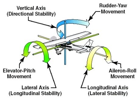 3.9.1 Concepts of stability and trim The aircraft's response to disturbance is associated with the inherent degree of stability; i.e. self-correction built in by the designer — in each of the three axes — that eventuates without any pilot action. Another condition affecting flight is the aircraft's state of trim — or equilibrium where the net sum of all forces equals zero, i.e. the aerodynamic forces are balanced and the aircraft maintains a steady flight condition when cruising, climbing or descending. Some aircraft can be trimmed by the pilot to fly 'hands off' for straight and level flight, for climb or for descent. But very light aeroplanes generally have to rely on the state of trim built in by the designer and adjusted by the rigger, although most have a rather basic elevator trim device, but no rudder or aileron trim facility. If natural trim is poor — and perhaps it flies with one wing low — inherent stability may maintain equilibrium with that wing-low attitude and not restore the aircraft to a proper wings-level attitude. In which case, the pilot has to maintain a slight but constant control column deflection to hold the wings level, which can be quite annoying. It is desirable that longitudinal trim doesn't change significantly with alterations in power, nor does directional trim change significantly with alterations in airspeed. An aircraft's stability is expressed in relation to each axis: lateral stability — stability in roll, directional stability — stability in yaw and longitudinal stability — stability in pitch. The latter is the most important stability characteristic. Lateral and directional stability have some inter-dependence. Degrees of stability An aircraft will have differing degrees of stability about each axis; here are a few examples: When disturbed a totally stable aircraft will return, more or less immediately, to its trimmed state without pilot intervention; however, such an aircraft is rare — and undesirable. We usually want a sport and recreational aircraft just to be reasonably stable so it is comfortable to fly. If overly stable they tend to be sluggish in manoeuvring and heavy on the controls; i.e. significant control force is required to make it deviate from its trimmed state. If it tends toward instability the pilot has to continually watch the aircraft's attitude and make the restoring inputs, which becomes tiring, particularly when flying by instruments. Some forms of instability make an aircraft unpleasant to fly in a bumpy atmosphere. The normally stable or positively stable aircraft, when disturbed from its trimmed flight state, will — without pilot intervention — commence an initial movement back towards the trimmed flight state but overrun it, then start a series of diminishing damping oscillations about the original flight state. This damping process is usually referred to as dynamic stability (or the tendency over time) and the initial movement back towards the flight state is called static stability. The magnitude of the oscillation and the time taken for the oscillations to completely damp out is another aspect of stability. Unfortunately a statically stable aircraft can be dynamically unstable in that plane; i.e. the oscillations do not damp out. The neutrally dynamically stable aircraft will continue oscillating after disturbance, but the magnitude of those oscillations will neither diminish nor increase. If these were oscillations in pitch, and if there were no other disturbances and the pilot did not intervene, the aircraft would just continue 'porpoising'. The negatively stable or fully unstable aircraft may be statically unstable and never attempt to return towards the trimmed state. Or it can be statically stable but dynamically unstable, where it will continue oscillating after disturbance, with the magnitude of those oscillations getting larger and larger. Significant instability is an undesirable characteristic, except where an extremely manoeuvrable aircraft is needed and the instability can be continually corrected by on-board 'fly-by-wire' computers rather than the pilot — for example, a supersonic air superiority fighter. The best piston-engined WWII day fighters were generally designed to be just stable longitudinally, neutrally stable laterally and positively stable directionally. 3.9.2 Longitudinal stability Longitudinal stability is associated with the restoration of aoa to the trimmed aoa after a disturbance changes it; i.e. if a disturbance pushes the nose up the tailplane will counter with a nose-down pitching moment. In section 6.2 we discussed the provision of a tailplane to act as a horizontal (longitudinal) stabiliser. Before we go any further we need to look at another structural aspect of the airframe. Angle of incidence Angle of incidence is a term that is sometimes mistakenly used as synonymous with wing angle of attack; however, the former cannot be altered in flight except in weight-shift control aircraft (hang gliders and trikes). Angle of incidence, usually just expressed as incidence, is within the province of the aircraft designer who calculates the wing aoa to be employed in the main role for which the aircraft is being designed, probably the aoa in performance cruise mode. The designer might then plan the fuselage-to-wing mounting so that the fuselage is aligned to produce the least drag when the wing is flying at the cruise aoa. Wings that incorporate washout will have differing angles of incidence at the wing root and at the outer section. A notional horizontal datum line is drawn longitudinally through the fuselage, and the angle between that fuselage reference line [FRL] and the wing chord line is the angle of incidence. Incidence should be viewed as the mounting angle of the fuselage rather than the mounting angle of the wings — see 'Stuff you don't need to know'. Incidence may also be called the 'rigger's incidence' or some similar expression carried over from the earlier days of aviation. For ultralight aircraft, incidence is something that should be checked at regular inspections by a qualified person Longitudinal dihedral An angle of incidence is also calculated for the horizontal stabiliser with reference to the FRL. The angular difference between wing and stabiliser angles is called the longitudinal dihedral, although it is probably more correct to say that the longitudinal dihedral is the angular difference between the two surfaces at their zero lift aoa. The angle of the line of thrust is also expressed relative to the FRL. Positive longitudinal dihedral — where the wing incidence is greater than that of the stabiliser — will help control a stall by ensuring that, if the aircraft approaches a stall, the wing will stall before the tail, giving the tail a chance to drop the nose. The tailplane of most very light 3-axis control aeroplanes is mounted in a position where the wing downwash may effect the angle of attack of the tailplane and that downwash angle increases as the wing angle of attack increases. It is the horizontal stabiliser area and moment arm that provides the restoring moment to return aoa to the trimmed state. However, bear in mind that the moment arm, which supplies the restoring leverage and thus the stability, is affected by the cg position. If the cg lies outside its limits, the aircraft will be longitudinally unstable. We learned in section 2.6 that when flying with level wings, at a particular weight, each aoa is associated with a particular IAS. We might as well take advantage of that by arranging the longitudinal dihedral so that the built-in state of trim produces a particular indicated airspeed. In some ultralights a designer/rigger might pick Vbg — best power-off glide speed — as the natural airspeed so that, lacking pilot input, the aircraft will naturally attempt to adjust its aoa to the Vbg aoa, whether power is on or off. Oscillating motions It is possible that an aircraft, properly trimmed for continuing level flight, may develop a 'phugoid' motion if affected by a sharp disturbance. A phugoid cycle is a pitch increase followed by a pitch decrease without any discernible aoa change, i.e. a short climb during which speed decreases and the nose drops into a short descent during which speed increases and the cycle starts again. The aircraft is trading kinetic energy for an increase in the potential energy of height, using the latter to return to the trimmed airspeed in the descent; the cycle time for one oscillation in a very light aircraft might be 20 seconds or so. The oscillating motion issometimes described as 'porpoising'. If the pilot doesn't intervene and the aircraft is phugoid stable the phugoid cycles will damp out after a few diminishing oscillations. If the aircraft is phugoid unstable the oscillations will diverge and the pilot must intervene. The longitudinal dihedral and the tail moment arm affect phugoid stability. 3.9.3 Directional stability Directional stability is associated with the realigning of the longitudinal axis with the flight path (the angle of zero slip) after a disturbance causes the aircraft to yaw out of alignment and produce slip; remember yaw is a rotation about the normal (vertical) axis. In section 6.3 we discussed the provision of a fin to act as a directional stabiliser. The restoring moment — the static stability — provided by the fin is the product of the fin area and the moment arm. The moment arm leverage will vary according to the cg position — the aircraft's balance. The area required for the fin has some dependency on the net sum of all the restoring moments associated with the aircraft fuselage and undercarriage side surfaces fore (negative moments) and aft (positive moments) of the cg. For instance, the Breezy has, except for the pilot's body, very little lateral moment ahead of the cg because of the open frame fuselage; thus a small fin provides all the moment necessary for directional stability. But if the pilot and passenger were enclosed in a cockpit or pod, with a much greater side surface, then the negative moments would be greater and consequently the fin area would have to be greater. If the pilot removes his/her feet from the rudder pedals the rudder, will 'float', aligning itself with the relative airflow and thereby reducing the restoring moment of the fin. The directional stability of very light aircraft with a lot of forward keel area — such as those with a cockpit pod and a 'boom' in place of a rear fuselage — may be 'conditional'; i.e. it is sensitive both to the position of the cg within its normal range and to the amount of sideslip. This is because the negative lateral forces of the pod are very much greater than the positive lateral forces of the boom and fin. Thus, beyond a certain angle of slip the moments change, positive stability is changed to neutral stability and yaw becomes locked in. It might also be associated with the fin stalling at high sideslip angles. The most noticeable symptom to the pilot is aerodynamic rudder overbalance (or 'rudder force reversal' or 'rudder lock') — where the rudder moves to full deflection without any additional pilot input, or doesn't return to the neutral position when the rudder pedal pressure is released, or the pedal force has to be reversed as sideslip angle is increased. It may require significant opposite rudder input, and probably an increase in airspeed, to return to the normal state. The areas of side surface above and below the cg also affect other aspects of stability. The term 'weathercocking' refers to the action of an aircraft, moving on the ground, attempting to swing into wind. It is brought about by the pressure of the wind on the rear keel surfaces, fin and rudder, which cause the aeroplane to pivot about one or both of its main wheels. It is usually more apparent in tailwheel aircraft because of the longer moment arm between the fin and the main wheels; although if a nosewheel aircraft is 'wheelbarrowing' with much of the weight on the nosewheel, then there will be a dangerously long moment arm between the nose wheel pivot point and the fin. 3.9.4 Lateral stability Lateral stability refers to roll stability about the longitudinal axis; in section 4.10 we established that ailerons provide the means whereby the aircraft is rolled in the lateral plane. However, unlike the longitudinal and normal planes where the horizontal and vertical stabilisers provide the restoring moments necessary for pitch and yaw stability, no similar restoring moment device exists in the lateral plane. But let's imagine that some atmospheric disturbance has prompted the aircraft to roll to the left, thus the left wingtip will be moving forward and down, and the right wingtip will be moving forward and up. Now think about the aoa for each wing — the wing that is moving down will be meeting a relative airflow coming from forward and below, and consequently has a greater aoa than the rising wing. A greater aoa, with the same airspeed, means more lift generated on the downgoing side and thus the left wing will stop going further down or perhaps even rise a little, although pilot action is usually needed to get back to a wings level state. This damping of the roll is known as lateral damping. So roll stability, except when at or very close to the stall, is intrinsic to practically all single-engined light aircraft. (When the aircraft is flying close to the stall, the aoa of the downgoing wing could exceed the critical aoa and thus stall, which will exacerbate the wing drop and might lead to an incipient spin condition. See the stall/spin phenomenon.) But — and there always seems to be a 'but' — when the aircraft is banked, other forces come into play and affect the process. If you re-examine the turn forces diagram in the manoeuvring forces module, you will see that when an aircraft is banked the lift vector has a substantial sideways component; in fact, for bank angles above 45°, that sideways force is greater than weight. So we can say that any time the aircraft is banked, with the rudder and elevators in the neutral position, an additional force will initiate a movement in the direction of bank; i.e. creating a slip. We know from the section 7.3 that the aircraft's directional stability will then yaw the nose to negate the slip and the yaw initiates a turn, which will continue as long as the same bank angle is maintained. There are several design features that stop the slip and level the wings, thus promoting lateral stability. For instance, placing the wing as high as possible above the cg increases so-called 'pendular stability', (The stability due to the high wing is not really pendulum stability such as that applicable to powered parachutes.) Wing dihedral* is usually employed with low-wing monoplanes (and to a lesser degree of tilt with high wings), where the wings are tilted up from the wing root a few degrees. A swept-back wing format is used with trikes. Another design method is anhedral, where the wings are angled down from the wing root, but it is unlikely to be used in light aircraft, although the powered parachute wing utilises an anhedral arc for stability. (*'Dihedral' is a mathematical term denoting the angle between two intersecting planes.) Spiral instability An aircraft with positive spiral stability tends to roll out of a turn by itself if the controls are centred. Some light aircraft with little or no wing dihedral and a large fin tend to have strong static directional stability but are not so stable laterally. If slip is introduced by turbulence or by the pilot, such aircraft — left to their own devices — will gradually start to bank and turn — with increasing slip and nose drop — and hence increasing turn rate and rapid increase in height loss. Neutral spiral stability is the usual aim of the designer. The turning process starts slowly in aircraft with slight spiral instability but leads to spiral divergence which, if allowed to continue and given sufficient height, will accelerate into a high-speed spiral dive. This often occurs when a pilot without an instrument flight rating strays into cloud where all visual cues are lost. In that condition it is known as the 'graveyard spiral'. Inadvertent entry into a fatal spiral dive, leading to inflight breakup, can happen even with experienced IFR pilots, see this Australian Transport Safety Bureau report. It is evident that directional stability and lateral stability are coupled (i.e. rotation about one axis prompts rotation about the other) and to produce a balanced turn; i.e. with no slip or skid, the aileron, rudder and elevator control movements and pressures must be balanced and coordinated. Dutch roll Induced motion in the lateral plane generally brings about a coupled motion in the directional plane, and vice versa. Dutch roll is a phenomenon in level flight where a disturbance causes a combined yaw and roll followed by a return to the level flight condition then a yaw and roll to the other side: the oscillations continuing until damped out. In a very light aircraft the time for each cycle might be 5 to 10 seconds. The motion is quite uncomfortable, viewed from the cockpit the wingtips complete a circular motion against the horizon as does the nose. Pilot intervention is by use of rudder. 3.9.5 Trim and thrust We have covered above the reaction of the aircraft to changes in relative airflow whether induced by the pilot or minor atmospheric turbulence. We know from sections 1.8 and 1.9 that if an aircraft is properly trimmed for cruise flight and we increase thrust then it will climb; and if we reduce thrust it will descend. But how this eventuates is not at all straightforward. The reaction to changing power, without the pilot touching the control column, depends on whether the cg is above, below or inline with the line of thrust; in the Breezy, the cg is below the thrust line. The thrust line is best located so that it passes close to the vertical cg position to minimise the initial pitching moments associated with power changes. The placement of the horizontal and vertical stabilisers, in relation to the propeller slipstream and to the wing downwash, affects flight performance and particularly flight at slow speeds — because then the total air velocity within the slipstream tube is nearly double that outside the tube; also the slipstream is rotating, and will thus impart a sideways moment to the fuselage and vertical stabiliser. Effects on individual aircraft types vary according to the designer's inbuilt compensations: for example, if the horizontal stabiliser operates in the wing root downwash airflow, then when the wing root stalls and the downwash becomes turbulent the stabiliser might undergo an abrupt change in aoa (and thus in its stability restoring moment). Or if the horizontal stabiliser operates substantially outside the downwash but if it is in the path of the turbulent flow from the stalled wing, it will then lose part of its aerodynamic force. If a modification is made to that design, even a seemingly minor change, the consequential effect on stability may be quite surprising. To illustrate the point, I suggest you read an "airworthiness report regarding (among other factors contributing to general stability problems) a small change made in relocating the exhaust manifold of a Thruster that, at a particular aoa, promoted turbulent flow over the upper wing surface, which then extended to the horizontal stabiliser, and reduced the stabilising moment imparted by that surface. Stuff you don't need to know The term 'decalage' (French = gap or shift forward/back) relates to the difference in the angles of incidence of the upper and lower mainplanes of a biplane. Decalage is now occasionally used as synonymous with longitudinal dihedral. The angle of incidence has some effect on the pilot's view over the nose. A very few naval aircraft designs have included 'variable incidence wings' where the angle of incidence could be changed by the pilot during flight, within a range of say 2–15°, using electric motors. Such aircraft included leading edge slats as a high-lift device.The idea was to take full advantage of the high maximum CL and consequent low speed, during the landing approach, without having the fuselage cocked up at a high angle blocking the view. As aoa increased and the aircraft slowed, the pilot wound the fuselage down, so that it remained more or less level during the approach and thus provided a better view of the flight deck! Variable incidence wings were also used with one of the post-WWII Supermarine amphibian designs. STRICT COPYRIGHT JOHN BRANDON AND RECREATIONAL FLYING (.com)
 -
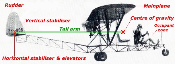 3.8.1 Airframe basics The empennage A monoplane has a single wing, or a left and right pair of wings — the port and starboard mainplanes. A biplane has two sets of wings mounted one above the other. The engine and propeller may be in front of the wing (a 'tractor' configuration) or behind the wing (a 'pusher' configuration). It must have some sort of pilot/passenger seating (usually enclosed in a cockpit or pod, which will have either tandem or side-by-side seating and is referred to as the 'occupant zone'); fuel tank(s); and a rigid structure mounting the engine/propeller, the wheels or undercarriage, and the cockpit, so that their weight is supported by the wing main spar(s) and the propeller thrust reaction is transmitted to the body and wings. The photograph of Mick McCann's 'Breezy' shows a basic high-wing monoplane, pusher-engine configuration with tandem pilot/passenger seating, nose-wheel undercarriage and an open-frame, welded tubular-steel fuselage — the aft part of which is upswept, so that the aircraft's attitude in pitch can be adjusted during take-off and landing without the tail striking the ground. Also the arrangement keeps the rear stabilising and control surfaces within the energetic airflow of the propeller slipstream. The term fuselage is derived from an old French word meaning a tapered 'spindle' used for manually weaving yarn. The 'Breezy' has no refinements for comfort — or for drag reduction. The fuel tank is not discernible in the photograph but is small and close to the engine. Attached to the rear fuselage are the horizontal stabiliser and elevators, plus the vertical stabiliser or fin and the rudder, together forming the pitch and yaw stabilising and control mechanisms — the tail assembly or empennage. The latter term is derived from a French word meaning to feather an arrow; maybe that is why some people refer to the empennage as the 'tailfeathers'. The horizontal stabiliser and elevators are referred to as the 'tailplane'. Moments and couples The moment of a force or the torque is a measure of the rotational effect produced by a force acting about — or with respect to — a fulcrum, axis, centre of mass (cg) or aerodynamic centre. Its magnitude is the product (in newton metres) of the force (N) and the length (m) of the arm (the leverage) from the pivotal point to the line of action of the force. The moment will act in a particular direction, for example, as we saw in the 'Aerofoils and wings' module, the pitching moment of a cambered wing produces a nose-down torque. The forces generated by the tailplane control surfaces are dependent on the stabiliser area, the control surface area, the length of the tail arm to the cg, the control surface deflection and the airspeed. Only deflection and airspeed are controlled by the pilot. Two equal and opposite forces acting parallel to each other, but separated, form a couple. The rotational effect or moment of a couple is the product of one force and the perpendicular distance between them. The ailerons, for example, form a couple when deflected. 3.8.2 Tailplane Horizontal stabiliser The existence of the wing pitching moment makes the wing inherently unstable. To overcome this problem, it is necessary to couple it with another aerodynamic moment about the lateral or pitch axis — opposing the wing pitching moment — that will balance that moment at an airspeed selected by the designer. The moment of a force is the arm length multiplied by the force; so the longer the tail arm, the smaller the aerodynamic force required. The standard solution is to extend the fuselage rearwards so that a horizontal stabiliser can be mounted at a distance from the cg; note the Breezy's very long tail arm – between the cg and the small horizontal stabiliser. The horizontal stabiliser is usually a lift-generating surface — or 'plane' — mounted so that the aerodynamic force it generates acts in the opposite direction to the lift from the mainplane, i.e. generally downwards. The plane could incorporate a cambered aerofoil with the cambered surface underneath, or perhaps a symmetrical aerofoil, or even just a flat plate — as the Breezy's appears to be. The symmetrical aerofoil and the flat plate would both be mounted at a negative incidence to produce the downward force. The end result is that the net pitching moment of the mainplane and tailplane couple is zero at a particular geometric aoa of the main wing; that aoa would equate with a speed selected by the designer — usually the designed cruise speed or perhaps the engine-off glide speed. The fuselage may also produce pitching moments that must be balanced by the stabiliser. As the horizontal stabiliser is usually designed to produce negative lift, then the wing must fly at a slightly greater aoa to provide additional lift, so that the net aircraft lift balances weight. Elevators The pilot must be able to initiate and hold aoa changes for airspeed adjustments, manoeuvres (accelerations) in the pitching plane (pull-ups, turns, push-downs) and adjustments of aircraft attitude relative to the airfield or alighting area surface during take-off and landing. The elevators — hinged to the trailing edge of the horizontal stabiliser so that they may be deflected up or down — are the control surfaces that enable controlled changes in wing aoa. Elevators are aerodynamically similar to the ailerons, but move in unison rather than differentially. The elevators are linked, via control rods or cables, to forward/backward movement of the control column, so the pilot can, in effect, increase or decrease the camber of the stabiliser–elevator combination. Camber changes will alter the magnitude and direction of the aerodynamic reactions generated by the stabiliser–elevator, and the changed forces impart a pitching moment in the longitudinal plane. This pitching moment rotates the aircraft about its lateral axis, initiating the change in wing aoa. Once the new aoa is established, the pitch moment returns to zero and the aircraft will hold that aoa — provided the elevators are held in the deflected position by the pilot or a trim device — thereby controlling airspeed for a given power setting. Backward movement of the control column raises the elevators and the aircraft's nose pitches up; forward movement lowers the elevators and the aircraft's nose pitches down. The force able to be exerted via the elevators is the most significant control force. The 'up' and 'down' terms in pitch are not relative to the horizon but to the original flight path in the aircraft's longitudinal plane. A stabilator is an 'all-moving' or 'all-flying' tailplane combining the horizontal stabiliser and elevator providing similar force with a lesser deflection, thus less drag. Sometimes used in higher speed light aircraft but rarely in very light aircraft. There may be some net advantages in mounting the stabiliser and elevators in front of the wing — a canard — but such arrangements are rather rare amongst very light aircraft. 3.8.3 Vertical stabiliser and rudder Because of drag and other effects, aircraft perform much better if their longitudinal axis is accurately aligned, in plan view, with the flight path. If unaligned, the aircraft velocity will have both a forward component and a slight lateral component, and the relative airflow — the flight path — will not be aligned with the longitudinal axis. Such bodily sideways (translational) movement along the lateral axis is called slip or sideslip or skid. The skid term is generally associated with excess 'bottom' rudder and skidding out in a turn, as a road vehicle might. Thus, some means is required to ensure that if the horizontal direction of the relative airflow is changed (i.e. the aircraft acquires slip because of a minor disturbance) then the aircraft will automatically yaw — rotate itself about its normal axis — to realign its longitudinal axis with the airflow, so that the sum of all the lateral moments — fore and aft of the cg — equals zero. The long-established means is to use a fin, or vertical stabiliser, mounted at the rear of the aircraft, that has an aerofoil section — usually symmetrical — or is just a flat plate. The fin applies the restoring moment to realign the longitudinal axis with the airflow. That moment does not realign the aircraft with its original flight path; after restoring alignment with the relative airflow, the aircraft may be aligned with a different flight path, depending on the amount of original displacement. The fin is often angled away from the aircraft's longitudinal axis by a few degrees. This offset creates an aerodynamic force that compensates for the rotating propeller slipstream applying a force to one side of the fin. The rudder is the control surface hinged to the fin and is the lateral plane equivalent of the elevators; though the rudder is operated by the pilot's rudder pedals rather than the control column. Pressure on the left pedal causes the rudder to deflect to the left, so that the fin/rudder act together as a cambered aerofoil to produce an aerodynamic force that pushes the tail to the right — and consequently the nose swings left; i.e. the aircraft yaws left. (Yaw is an old nautical term associated with the motion of the sea swinging the bow off-course.) The amount of yaw, at a given airspeed, is dependent on the degree of rudder deflection. (But, of course, it is primarily dependent on the tail moment arm and rudder area.) The aircraft will continue yawing if the rudder deflection is held by the pilot, but as the aircraft turns (i.e. it is rotating about its normal or vertical axis while moving forward), the wing on the outside of the turn must be moving slightly faster than the inner wing and thus generates more lift. The increased lift will raise the outer wing and the aircraft will enter a banked turn, but will tend to skid out because the bank angle will not be correct for the turn. Only one bank angle will produce the desired radius or rate of turn for a particular airspeed. Note the Breezy's small fin with its relatively large rudder. The pilot's feet are on the pedals linked to the rudder and he is holding the control column — linked to the ailerons and the elevators — with one hand. The other hand is probably holding the engine throttle lever. The rudder initiates yaw about the normal axis; the ailerons initiate roll about the longitudinal axis; the elevators initiate pitch movement about the lateral axis. 3.8.4 Control balance Aerodynamic balance Aircraft designers try to impart a good 'feel' to the controls so that the pilot finds they are not too 'heavy' or too 'light' to operate through most of the speed range. So, the elevators and rudder are usually fitted with some sort of aerodynamic balance, which puts part of the control surface forward of the hinge line. Such devices might be inset hinge balances, leading-edge balances or control horns that reduce the hinge moments needed to deflect the control surface. Mass balance Control surfaces need to be hinged near the leading edge, the centre of their mass will be well aft of the hinge line; i.e. the mass of the control is not statically balanced. That, combined with the necessary elasticity of aircraft structures, leads to a control flutter problem. This might occur with mass unbalanced control surfaces at any speed, but particularly with ailerons at high speed. Flutter has the potential to lead to structural failure. The prime solution to the mechanical unbalance and the flutter problems is for the manufacturer to accurately balance the mass of the control surface by inserting weights forward of the hinge line usually within the hinge insets or the control horn. This — known as mass balance — increases the stability of the control surface and ensures that accelerations don't deflect the control surface. Notes for scratch-builders You may occasionally come across the terms tail volume and tail volume ratio. The horizontal tail volume is the surface area of the horizontal stabiliser plus elevators multiplied by the length of the moment arm of the horizontal stabiliser measured from the wing MAC quarter chord to the horizontal tail MAC quarter chord. The horizontal tail volume ratio or tail volume coefficient is the tail volume divided by the product of wing area and wing MAC. Tail volume ratio is usually in the range 0.35 to 0.45 for minimum aircraft and 0.45 to 0.55 for aircraft of composite construction — when the units of measurement are feet. The higher the coefficient value, the more stable the aircraft. There is a similar equation for the vertical stabiliser and rudder, but the divisor is the product of wing area and wing span. Such ratios are of interest to an aircraft designer, as there is a linear relationship between tail moment or tail area, and stability — doubling the tail moment or the tail area doubles the static stability and quadruples the dynamic stability. The aspect ratio of the tail affects tailplane pitching moments; for a given area higher aspect ratio produces less induced drag and hence the lift component of the aerodynamic force is higher. STRICT COPYRIGHT JOHN BRANDON AND RECREATIONAL FLYING (.com)
 -
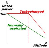 3.7.1 Engine power output Engine power equals the product of force and speed. Torque is the rotational force acting about the engine crankshaft multiplied by the moment arm; i.e. it is the product of the firing stroke in the cylinder and the radius of the crank to which the connecting rod is attached. The bigger the cylinder the bigger the rotational force — the 'bang'. Engine speed is measured in crankshaft revolutions per minute [rpm]. In the 'Manoeuvring forces' module we discussed the power required for various flight conditions, and looked at power required/power available curves and the effect of altitude on power output. It may be appropriate to review section 1.7 of that module. Normally aspirated aero engines The maximum power that can be developed, in the cylinders of a particular piston engine, increases or decreases directly with the density of the air in the intake manifold, and air density decreases as altitude increases — or temperature increases. See the atmospheric density and the International Standard Atmosphere sections in the 'Airspeed and the properties of air' module. Thus, the full throttle power output of a normally aspirated engine — one that relies solely on the ambient atmospheric density — decreases as operating altitude increases. The diagram in section 1.7 shows how maximum brake horse-power [bhp], delivered at full throttle in a normally aspirated engine, decreases with altitude. A 100 hp engine operating at 65% power will be delivering 65 hp. Power produced is proportional to the air density at the intake manifold, the cylinder displacement and compression ratio, the number of cylinders, and the rpm. Of those items, only the air density at the intake manifold and the engine rpm alter, or can be altered, during flight. (With a normally aspirated engine and a propeller whose pitch is not variable in flight, the throttle controls manifold pressure, which then determines rpm.) A traditional four-stroke light aircraft engine, such as the Lycoming O-235, has an individual cylinder displacement of 950 cc, a compression ratio of 7:1 and a maximum design speed of 2600 rpm, at which its rated 110 bhp is produced — in sea-level ISA conditions. The Rotax 912, the most common lightweight four-cylinder aero-engine, utilises an individual cylinder displacement of only 300 cc, a compression ratio of 9:1, but doubles the maximum design speed to 5500 rpm to achieve its rated 100 bhp. The lightweight Jabiru 2200 utilises an individual cylinder displacement of 550 cc, a compression ratio around 8:1 and a maximum design speed of 3300 rpm to achieve its rated 80 hp. The three engines mentioned are all horizontally opposed, four-stroke and four-cylinder; a popular configuration providing a fully balanced engine that doesn't require crankshaft balance weights. Engines are often described in terms of 'total capacity' (cylinder displacement by number of cylinders) in litres or cubic centimetres. Thus, the Lycoming O-235 is 3.8 litres or 3800 cc (235 cubic inches), the Rotax 912 is 1.2 litres and the Jabiru 2200 is 2.2 litres. Most engines used in ultralights tend to be around 30% lighter (in terms of weight per rated hp) than the ubiquitous Lycoming and Continental piston engines used in general aviation aircraft. Thus, they are cheaper to manufacture but less robust, with a consequent shorter time between overhaul [TBO]. Although aero-engines can quite happily operate continually at their rated power, doing so is not good practice. It is uneconomical in terms of fuel efficiency, but — more importantly — it may shorten engine life, if engine operating temperatures and pressures are exceeded. Normally the maximum — and optimum — power setting for continuous cruise operation is 75% of rated power. Turbo-charged aero-engines The volumetric efficiency (i.e. the cylinder-filling capability) of an engine can be improved by increasing the density of the fuel/air charge delivered to the cylinders by compressing the air in the atmospheric intake manifold. This process is supercharging and develops more torque at all engine speeds. The compressor is usually a lightweight centrifugal impeller driven by a gas turbine that utilises the otherwise wasted energy of the engine exhaust gases. Such a system is a turbine-powered supercharger, usually described as a turbocharger. An oil pressure-driven butterfly valve or waste gate is incorporated within the exhaust manifold system, automatically adjusting — according to the pressure within the intake manifold — to allow all, or a portion, of the exhaust gases to bypass the turbine; thus continually maintaining the system within the designed operating limits. There is a slight penalty in that turbocharging also increases the temperature of the charge. This consequently decreases the achievable density and possibly leads to detonation, unless a charge cooling device — an intercooler — is incorporated between the compressor and the cylinders. For some information on mechanically powered supercharging, read this magazine article. Turbocharging may be used to increase the sea-level rated power of the engine, but the use of that full throttle power at low altitudes would normally be limited to short periods because of engine temperature limitations. The big advantage is the increase in power available at altitude. The diagram plots the power achieved (percentage of rated power) at full throttle, in ISA standard conditions, for a normally aspirated engine and the turbocharged version. The turbocharged engine can maintain its rated power from sea-level up to the 'critical altitude', probably around 6000 or 7000 feet, after which it will decrease. The waste gate would probably be fully open at sea-level and then start closing as altitude increases — so that it would be fully closed at, and above, the critical altitude. Turbocharging raises the service ceiling of the aircraft. The service ceiling is the ISA altitude at which the aircraft's best rate of climb (from an extended climb starting at MTOW and unassisted by any atmospheric phenomena) drops below 100 feet per minute — regarded as the minimum useful climb rate. This should be the aircraft's ceiling quoted by the manufacturer. The Rotax 914 series 115 hp turbocharged engines are often regarded as just being suitable for ultralight aircraft. However, those engines power the Predator RQ1/MQ1, unmanned aerial reconnaissance and surveillance vehicles, used so successfully in the Afghanistan and Iraq campaigns of recent years. The Predators have a maximum take-off weight around 1000 kg, cruise around 90 knots, normal mission duration around 20 hours — but could operate for 40 hours — and service ceiling of 25 000 feet. They often carried two 50 kg Hellfire missiles for attacking acquired targets — they also need 5000 feet of paved runway for take-off. Two-stroke aero-engines The lower power (say, up to 65 hp) engines used in ultralight aircraft are usually two-stroke engines, although the half-VW four-stroke auto engine conversions are around 40 hp. Two-strokes don't have very good volumetric efficiency, and the engine is generally efficient only in the upper 30% of its rpm and throttle opening range. In fact, ultralight two-strokes tend to run very roughly at speeds below 2500 rpm and achieve their rated power at rotational speeds in the 5500 to 6500 rpm range. The three most common two-strokes are two-cylinder models with individual cylinder displacements around 250 cc; they achieve their rated power at 6500 rpm and 75% power at around 5300 rpm. Fuel efficiency drops off very quickly as rpm is reduced below the 75 % power figure; see the Rotax two-stroke engine operator's manual section 10.2. Gearing or belt reduction is used to improve the torque delivered to the propeller shaft while also reducing the rpm to something more suitable for the propeller. The torque increases because of the larger rotational radius of the driven gear. The big advantage with two-stroke engines is their mechanical simplicity, and consequent weight and cost saving, because they lack the camshaft and associated valve train of the four-strokes. Some very small (15 hp) two-strokes are used to power self-launching powered hang-gliders. Between 1999 and 2003, there were 98 engine failures reported to RA-Aus; 39 were two-stroke engines and 59 were four-stroke. It is estimated at that time about 65% of the ultralight fleet, of some 1800–2000 aircraft, were equipped with two-strokes. It would appear during that period the two-strokes were more reliable than the lightweight four-stroke aero-engines, though the development of lightweight four-strokes was then not as far along the learning curve as two-stroke development. 3.7.2 Propeller power output Propeller efficiency An aircraft engine supplies energy, in the form of rotational power, to the propeller shaft. The propeller converts the rotational power to thrust power, either pulling the aircraft along behind it (a tractor installation) or pushing the aircraft in front of it (a pusher installation). The pusher installations are usually the only options when the engine is mounted on a carriage or cart rather than a fuselage structure. That option is the standard for trikes, nanolights and gyroplanes. The 10 hp or so engines attached to the 'backpack' harnesses of powered hang gliders and powered paragliders are, of course, pushers. The major problem with pusher propellers in very light aircraft is the avoidance of something from the occupant zone — just in front of the engine — moving through the propeller disc or being entangled in it. The propeller accelerates a tube of air, with much the same diameter as the propeller disc; i.e. it adds momentum to the tube of air and the reaction force propels the aircraft forward. The velocity of this accelerated airstream (the slipstream) has both rotational and rearward components. Momentum = mass × velocity, so if the mass of air passing through per second is increased by increasing the diameter of the propeller, the rearward velocity imparted can be decreased but still produce the same rearward or axial momentum. The rate at which axial momentum is imparted to the air equates with thrust. Propeller efficiency is the ratio of the thrust power (thrust × aircraft forward speed) output to the engine power input. The work done (the energy expended) by the propeller is the kinetic energy imparted to the slipstream = ½mv² joules (if mass is in kilograms and v in metres per second), so less energy is expended if the mass is increased and the velocity decreased. Using a simplified static thrust example, if m = 10 kg and v = 100 m/s, then the momentum is 1000 kg·m/s and energy expended is ½ × 10 × 100² = 50 kJ. But if the values for m and v are interchanged (i.e. m = 100 kg and v = 10 m/s) the momentum will still be the same but the energy expended will be decreased substantially; i.e. ½ × 100 × 10² = 5 kJ. Thus, the most efficient system is to utilise the greatest propeller diameter possible — limited by: the stress effects on the engine (the gyroscopic moments increase exponentially with diameter; see below) ground clearance requirements in worst conditions (e.g. heavy landing and deflated tyre) propeller blade strength – centrifugal forces are extremely high, much greater than aerodynamic forces, even a lightweight blade would be experiencing forces around 2500g. blade tip speed. When a propeller is rotating, the speed at any point on a blade is the product of the rpm and the distance of that point from the hub, and thus the speed at the propeller tip is the greatest. Compressibility constraints dictate that the speed at the blade tips should not exceed about Mach 0.85 — 560 knots or 290 m/s at sea-level. But significant compressibility effects become evident at 250 m/s and, if the propeller is close to the pilot, the noise may be extremely uncomfortable. So, for comfort, tip speed is usually in the range 200–240 m/s. it is not only the aircraft occupants who must be comfortable with the noise, there are restrictions on engine and propeller noise in the vicinity of aerodromes – see the aircraft noise regulations. For light aircraft engine/propeller systems, it is usual to restrict propeller speed to less than 3500 rpm; so, the high rpm engines must incorporate a gear-driven or belt-driven propeller speed reduction unit [PSRU] between the crankshaft and the propeller shaft. The rotational speed of the fixed-pitch propeller depends on the pitch of the blades, the power supplied to the propeller and the aircraft velocity. Propeller blade area is an important consideration in propeller design and choice. Blade aspect ratio is usually maintained around 6–8; so, with a limited propeller diameter, blade area can only be increased by increasing the number of blades. Matching engine and propeller Propellers must be carefully matched with the characteristics of the airframe, engine and reduction gear to which they are mated. The engine must be neither underloaded nor overloaded. At best, a mismatch could make the engine and aircraft incapable of delivering its designed performance, or create the situation where the engine cannot be opened up to full throttle because the lack of load (see the following paragraph) would take the rpm beyond the red-line limit, or it could result in crankshaft or crankcase fracture. At worst, a mismatch could lead to torsional vibration or propeller blade destruction induced by centrifugal force. This can readily cause the engine to dismount from the airframe and lead to consequent total loss of the aircraft. When discussing the power required curve it was noted that power required is proportional to aircraft velocity cubed. Similarly, the power delivered by a propeller varies in accordance with rpm cubed (if everything else is kept constant). Thus, the load on the propeller may be substantially increased just with a relatively minor further increase in rpm when operating at high rpm, which can lead to loss of the blades. Note that centrifugal forces on the blades change in accordance with the rpm squared. Note: The load on the engine is the propeller torque. When the aircraft is stationary, with the engine throttle wide open, the propeller torque and the static thrust generated (i.e. the efficiency of the engine and the propeller combination) depend on the propeller pitch. If the pitch is zero or slightly negative, the static thrust will be zero and the propeller torque will be very low so that the engine will race — overspeed — and lose power because of inefficient cylinder charging, etc. On the other hand, if the pilot is able to set the prop to a more negative pitch, then reverse thrust will be generated together with sufficient torque to maintain constant engine rpm and the aircraft will move backward. If the pitch is 'fine' (low aoa), the propeller will generate near maximum static thrust and sufficient torque to maintain high engine rpm, thus delivering ample power to the propeller shaft. This is the ideal situation to get the aircraft rolling for take-off and climb-out. If the pitch is very 'coarse' (high aoa), then static thrust is low but propeller torque is very high, which will slow the engine. This is the worst situation for take-off — the aircraft will move forward sluggishly and, hopefully, never reach take-off speed. For an interesting article on ground testing of aircraft engines for power output, read "Testing one, two three" in the July-August 2002 issue of 'Flight Safety Australia' magazine. When an aircraft with a fixed-pitch propeller is flying the back of the power curve (i.e. an increasing thrust power output is needed as the airspeed decreases), the propeller efficiency will decrease as airspeed decreases, while the increasing propeller torque will be slowing the engine power. Thus, it may be difficult to arrest any sink that develops at low speeds — as might be experienced on the approach to a short-field landing. However, even with an apparently well-matched engine/propeller combination, there may be a certain rpm range (or ranges) where the frequency of a particular engine vibration resonates, with some natural frequency of the propeller, to produce an intrusive vibration and a potentially damaging stress cycle. In such aircraft, that rpm range or ranges is (or should be) indicated as a yellow, perhaps red, arc on the face of the engine tachometer. Rpm settings within those ranges should not be used. Any gyroscopic moment induced depends on the rate of change in aircraft pitch or yaw, and the rotational speed and moment of inertia of the propeller. Its mass moment of inertia depends on propeller mass and diameter. The gyroscopic loads are transferred to the airframe via the engine crankshaft, crankcase and mountings. Under some conditions, gyroscopic loads may lead to crankshaft/crankcase failures. See 'The Fox story'. The failure conditions usually identified are the use of a propeller of excessive diameter (the moment of inertia increases exponentially with diameter) possibly combined with an excessive 'overhung' moment — the distance from the propeller cg to the engine. Excessive gyroscopic loads may also be placed on the crankshaft/crankcase by using brake, rudder and a burst of throttle to swing an aircraft rapidly when taxiing. The flight conditions that follow propeller blade failure cannot be simulated in training, but an extreme out-of-balance condition (loss of one blade for example) can very quickly shake the engine from its mountings. 3.7.3 Propeller types The following is a copy of a document authored by Marcus Graney and published on the web site of the New Zealand manufacturer of Airmaster propellers. I have added the notes presented in italic. ... JB The most common type of propeller in sport aviation is the fixed-pitch propeller. Although cheap, this is one of the crudest propulsion devices you could use, and has been superseded by a variety of more advanced options, now readily available on the market. But, how do you know how each type of propeller operates and what advantages the different types offer? How are you going to choose between the different types available for your aircraft, especially considering that a more capable propeller is also more expensive? There are four common families of propeller, which I will introduce to you. They are fixed-pitch, ground-adjustable, inflight-adjustable and constant-speed. The last two are both examples of variable-pitch propellers. In order to appreciate the advantages which are characteristic of the different families of propeller, we must first consider the most fundamental characteristic of a propeller — the pitch. Pitch is important, as it is the manner in which pitch is controlled that allows us to differentiate between one family of propeller and another. A useful analogy when considering the affect of pitch is that of an automobile gearbox. By comparing a propeller's pitch to a gear ratio, and considering the function of a gearbox, we will gain an appreciation of the different families of propellers. What is pitch? Propeller theory includes a variety of concepts that may at times be called pitch. Pitch can refer to the blade angle with respect to a flat plane, the distance that a propeller will advance through the air for each rotation or the amount of "bite" that the blade has on the air. Essentially these concepts all describe the same thing. To use our automobile analogy, pitch is like the gear ratio of the gearbox. The important thing to note with pitch, is that it is available in a wide variety of degrees, or 'amounts', much like different gear ratios. To demonstrate, consider the following examples: A fine pitch propeller has a low blade angle, will try to move forward a small distance through the air with each rotation, and will take a 'small' bite of the air. It requires relatively low power to rotate, allowing high propeller speed to be developed, but achieving only limited airspeed. This is like having a low gear in your automobile. A coarse pitch propeller has a high blade angle, will try to advance a long distance through the air with each rotation, and will take a big 'bite' of the air. It requires greater power to rotate, limiting the propeller speed that can be developed, but achieving high airspeeds. This is like having a high gear in your automobile. Pitch and the different families of propellers As we saw above, pitch is a key element in the description of propellers (along with other factors such as diameter and blade area). When considering the four families of propellers it is useful to start with the simple fixed-pitch propeller, and look at the enhancements in pitch control that are gained as we progress through each family to the most advanced, the constant-speed propeller. Fixed-pitch propeller With a fixed-pitch propeller, the pitch of the propeller is fixed from manufacture. The performance of your aircraft is determined on the day your propeller is fitted, and is going to be limited within the constraints of the propeller. An analogy with an automobile is as though you had only one gear. Often when choosing a fixed-pitch propeller for your aircraft, manufacturers give you a choice of either a climb or a cruise prop. A climb propeller has a relatively fine pitch and a cruise propeller has a relatively coarse pitch. This is like a car manufacturer giving you a choice of a low or a high gear. Either you will be really slow off the mark, or your engine is going to have to be red-lined to get anywhere at a reasonable speed. Ground-adjustable propeller Many propellers manufactured and sold for ultralight and experimental aircraft are ground-adjustable. These propellers have the advantage of being able to have their pitch set before each flight if required, taking into account the type of flying you intend to do. More usually however they are used as a low cost way to try out various pitches and settle on the propeller pitch that best suits your aircraft and your style of flying. This can be compared to having a gearbox in your car that you can only change before you set out on your journey. Variable-pitch propeller With a variable-pitch propeller, you really have choices. To use the automobile analogy again, your car now has a real gearbox that you can change gear with on the go. (I hope that your car can do this at least!) In addition, rather than being limited to 4 or 5 gears, you can utilise any pitch along the continuum from maximum to minimum. The pitch of the propeller may be controlled in flight to provide improved performance in each phase of flight. Typically you would take-off in a fine pitch (low gear) allowing your engine to develop reasonable revs, before increasing the pitch (change up gears) as you accelerated to your cruising speed. You'll end up with the propeller at a relatively coarse pitch, (high gear) allowing the miles to pass beneath you at a rapid rate, while your engine is gently ticking over at a comfortable speed. This feature of a variable-pitch propeller will provide you with performance advantages, including: Reduced take-off roll and improved climb performance. Fine pitch allows the engine to reach maximum speed and hence maximum power at low airspeeds. Vital for take-off, climb, and for a go-around on landing. Improved fuel efficiency and greater range. Coarse pitch allows the desired aircraft speed to be maintained with a lower throttle setting and slower propeller speed, so maintaining efficiency and improving range. Higher top speed. Coarse pitch will ensure your engine does not overspeed while the propeller absorbs high power, producing a higher top speed. Steeper descent and shorter landing roll. With a fine pitch and low throttle setting, a slow turning propeller is able to add to the aircraft's drag, so slowing the aircraft quicker on landing. Variable-pitch propellers actually come in a variety of versions. These different versions refer to the different ways that they are controlled, and include: Two-position propeller. Inflight-adjustable propeller. Automatic propeller. Constant-speed propeller. A couple of these are now of historic interest only, so lets concentrate on the two most common options these days; the inflight-adjustable operation and the constant-speed propeller. The inflight-adjustable propeller allows the pilot to directly vary the pitch of the propeller to the desired setting. Combined with the throttle control, this control allows a wide variety of power settings to be achieved. A range of airspeeds can be maintained while keeping the engine speed within limits. While rare in larger aircraft, the inflight-adjustable propeller is the most common type of variable-pitch propeller that is encountered in sport aviation. When operated in manual mode, the Airmaster propeller is an example of an inflight-adjustable propeller. Constant-speed propeller The constant-speed propeller is a special case of variable pitch, which is considered in a family of its own, and offers particular operating benefits. With constant speed control, the pitch of the variable-pitch propeller is changed automatically by a governor. After the pilot sets the desired engine/propeller speed with the propeller speed control, the governor acts to keep the propeller speed at the same value. If the governor detects the propeller speed increasing, it increases the pitch a little to bring the speed back within limits. If the governor detects the propeller speed decreasing, it decreases the pitch a little to bring the speed again back within limits. This operation may be compared to an automatic gearbox in an automobile, where the gears are changed automatically to keep the engine operating at a reasonable speed. (The governor or constant speed unit [CSU] may be an electronic device that detects the rotational speed of a slip-ring incorporated in the propeller hub, and controls operation of a servomotor/leadscrew pitch change actuator in the hub assembly. Or, it may be an hydraulic fly-ball governor attached to the engine, using engine oil to operate a hydraulic pitch change piston in the hub assembly. In the first case, the cockpit control device is likely to be knobs and switches. In the hydraulic system, the governor is likely to be cable operated from a cockpit lever — JB.) A constant-speed propeller will automatically deliver you the advantages outlined above for variable-pitch propellers, with almost no control required from the pilot. Once a propeller/engine speed is selected, the pilot is able to control the power purely with the throttle (actually controlling the absolute pressure of the fuel/air mix in the intake manifold [MAP] which then determines power output) and the controller will act to keep the propeller/engine speed at the selected setting. While allowing the pilot to ignore the propeller for most of the time, the pilot must still choose the most appropriate engine/propeller speed for the different phases of flight: Take-off, go-around and landing. A high speed setting is used when maximum power is needed for a short time such as on take-off. The high speed setting may also be used to keep the propeller pitch low during approach and landing, to provide the desired drag and be ready for a go-around should it be required. Climb and high speed cruise. A medium speed setting is used when high power is needed on a continuous basis, such as during an extended climb, or high speed cruise. Economic cruise. A low speed setting is used for a comfortable cruise with a low engine speed. This operation produces low fuel consumption and longer range, while the advantages of low noise and low engine wear are also enjoyed. When operated in automatic mode, the Airmaster propeller is an example of a constant-speed propeller. Special pitch modes As well as the ability to vary the pitch of the propeller to optimise the aircraft performance, some variable-pitch propellers have some other special modes of operation that can be very useful in certain circumstances: Feather. A feathering propeller can alter the pitch of the blades up to almost 90 degrees. That is, the blade pitch is changed so that they have their leading edge pointing right into the direction of flight, offering minimum resistance to the airflow. This mode allows the propeller rotation to be stopped, without adding excessive drag to the aircraft. Feather may be used to improve the performance of the aircraft after the failure of an engine, but more usually in light aircraft it is used in motor glider applications. Here the engine is used to gain altitude, before the engine is switched off, the propeller feathered, and then gliding flight commenced. Reverse. A reversing pitch propeller can alter the pitch of the blades to a negative angle. That is, the blade pitch is changed so that they have their leading edge pointing slightly opposite to the direction of flight. This mode allows reverse thrust to be developed by the propeller. In larger commuter and transport aircraft this feature is often used to slow the aircraft rapidly after landing, but in sport aircraft it is more usually used to enhance manoeuvring on the ground. A popular application is in seaplanes, where the ability to manoeuvre backwards, and sometimes to reduce the thrust to nothing, is especially useful. This overview was designed to assist the understanding of how the ability to control propeller pitch is used to categorise the different families of propeller design. More importantly it has illustrated that as we progress from one design family to another, we realise significant improvements in performance, effectiveness and efficiency. While a family of propellers that offers better performance is likely to be more expensive to purchase, you can expect that over time the efficiency of a higher performance propeller will produce savings that will offset the initial cost. In addition your flying will be a more relaxed and enjoyable experience! When deciding what type of propeller to buy for your aircraft, you have to weigh up the relative advantages and costs. To help, we can summarise the most common families of propellers, and make a simple comparison of their respective advantages in cost and capability. Marcus Graney Aeronautical Engineer November 2000 There is another type of propeller that is quite rare; the single-blade propeller and, more particularly, the single-blade folding propeller associated with low-power engines in motor-gliders, see 'Single-blade propellers in very light aircraft'. 3.7.4 Propeller theory The forces Propeller blades are constructed using aerofoil sections to produce an aerodynamic force, in a similar manner to a wing. Consequently, the blades are subject to the same aerodynamics — induced drag, parasite drag, wingtip vortices, lift/drag ratios at varying aoa, pressure distribution changing with aoa, etc. There is a difference in application because, in flight, the propeller has rotational velocity added to the forward velocity. Thus, the flight path of any blade section is a spiral — a helical flight path. The diagram at left represents a blade section in flight and rotating about the shaft axis. Because of the different application, it doesn't serve much purpose to express the resultant aerodynamic force as we would for a wing; i.e. with the components acting perpendicular (lift) and parallel (drag) to that helical flight path, as in the upper figure. So, we resolve the aerodynamic force into the component acting forward and aligned with the aircraft's longitudinal axis as the thrust force, and that acting parallel to the direction of rotation as the propeller torque force. As you see in the lower figure the component of the 'lift' acting in the rotational plane has now been added to the 'drag' to produce the 'propeller torque force' vector. The remaining forward-acting portion of 'lift' is then the thrust. That is why propeller efficiency is usually no greater than 80–85%; not all the 'lift' can be used as thrust, and the propeller torque force consumes quite a bit of the shaft horsepower. The propeller torque and the engine torque will be in balance when the engine is operating at constant rpm in flight. Centrifugal force imposes considerable tensile stress while trying to pull the blades from the hub. Torque reaction applies bending stress to the blades in the reverse direction of rotation while the thrust force tends to bend the outer sections of the blades forward. The centrifugal twisting moment tends to twist the blades to a decreased (finer) pitch and the aerodynamic twisting moment (similar to the wing pitching moment) tends to twist the blades to a coarser pitch. The air inflow at the face of the propeller disc also affects propeller dynamics. Blade angle and pitch Although all parts of the propeller, from the hub to the blade tips, have the same forward velocity, the rotational velocity — and thus the helical path of any blade station — will depend on its distance from the hub centre. Consequently, unless adjusted, the angle of attack will vary along the length of the blade. Propellers operate most efficiently when the aoa at each blade station is consistent (and, for propeller efficiency, that giving the best lift/drag ratio) over most of the blade, so a twist is built into the blades to achieve a more or less uniform aoa. The blade angle is the angle the chord line of the aerofoil makes with the propeller's rotational plane and is expressed in degrees. Because of the twist, the blade angle will vary throughout its length. So, normally the standard blade angle is measured at the blade station, 75% of the distance from the hub centre to the blade tip. The angle between the aerofoil chord line and the helical flight path (the relative airflow) at the blade station is the angle of attack and the angle between the helical flight path and the rotational plane is the angle of advance or helix angle. The aoa and helix angle vary with rotational and forward velocity. The basic dimensions of propellers for light aircraft are usually stated in the form of number of blades, and diameter and pitch with values in inches; e.g. 3-blade 64" × 38". The pitch referred to is the geometric pitch that is calculated for any blade station, but usually the station at 75% radius. Geometric pitch = the circumference (2πr) of the propeller disc at the blade station multiplied by the tangent of the blade angle. Thus, it is the distance the propeller — and aircraft — would advance during one revolution of the propeller if the blade section followed a path extrapolated along the blade angle. e.g. For a blade station 24 inches from the hub centre (0.75r) and a 14° blade angle, the circumference = 2 × 3.14 × 24 = 150 inches, and tangent 14° = 0.25. Thus, the geometric pitch is 150 × 0.25 = 38 inches. Propellers are usually designed so that all blade stations have much the same geometric pitch. Designers may establish the ideal pitch of a propeller, which is the theoretical advance per revolution that would cause the blade aerofoil to be at the zero lift aoa; thus, it would generate no thrust and, ignoring drag, is the theoretical maximum achievable aircraft speed. The velocity that the propeller imparts to the air flowing through its disc is the slipstream. Slip used to be described as the difference between the velocity of the air behind the propeller (i.e. accelerated by the propeller) and that of the aircraft. Nowadays, slip has several interpretations, most being aerodynamically unsatisfactory, but you might consider it to be the difference, expressed as a percentage, between the ideal pitch and the advance per revolution when the the propeller is working at maximum efficiency in converting engine power to thrust power. Slip in itself is not a measure of propeller efficiency; as stated previously, propeller efficiency is the ratio of the thrust power (thrust × aircraft velocity) output to the engine power input. Pitch and velocity The performance of aircraft fitted with fixed-pitch or ground-adjustable propellers is very much dependent on the chosen blade angle. Fixed-pitch propellers limit the rpm developed by the engine at low forward velocity, such as occurs during the take-off ground roll; they may also allow the engine rpm to exceed red-line maximum when the load on the engine is reduced, such as occurs in a shallow dive. Fixed-pitch propellers operate at best efficiency at one combination of shaft power and airspeed. Blade angle is usually chosen to produce maximum performance at a particular flight condition, for example: • Vy climb; i.e. a climb propeller • Vc cruise; i.e. a cruise propeller. The climb propeller is usually chosen when the aircraft normally operates from a restricted airfield or in high density altitude conditions. The climb propeller will produce maximum efficiency at full throttle around the best rate of climb airspeed and will perform fairly well at take-off. But during the initial take-off acceleration, even the climb propeller may restrict the engine rpm to less than 75% power. The cruise propeller will achieve maximum efficiency at 75% power at airspeeds around the design cruising speed but aircraft take-off and climb performance will not be the optimum. The cruise propeller usually has a little more pitch than the standard propeller fitted to the aircraft. A high-speed propeller might be fitted when the aircraft is intended to be operating at, or above, rated power for short periods — in speed competition, for example. A variable-pitch constant-speed propeller allows the engine to develop maximum rated power and rpm during the ground roll, and to develop full power throughout its normal rpm range. With a constant-speed propeller, the pilot controls the inlet manifold absolute pressure [MAP] with the throttle lever and the engine rpm with the rpm control lever or knob/switches. (MAP is the pressure of the air/fuel mixture being delivered to the cylinders and is usually measured in inches of mercury [in/Hg] rather than hectopascals. Standard sea-level barometric pressure is 29.92 in/Hg or 1013.2 hPa.) The aircraft flight manual usually provides the pilot with several combinations of rpm/MAP to achieve a particular power setting. For example, in one particular aircraft, the recommended combinations for 65% power at sea-level are 2100 rpm + 26 in/Hg MAP, or 2200 rpm + 25 in/Hg, or 2300 rpm + 24 in/Hg, or 2400 rpm + 23 in/Hg. So, you can use low rpm and high MAP, or high rpm and low MAP, to achieve exactly the same power output. The 2100 rpm/26 in/Hg low rpm/high MAP combination probably gives more efficient cylinder charging and better combustion plus less friction. The high MAP also acts as a cushion in the cylinders, reducing engine stress. Obviously, if a constant-speed propeller is fitted to an aircraft then an intake manifold pressure gauge — marked with the allowable engine operating ranges — must be fitted, otherwise excessive manifold pressure (which raises the cylinder compression pressure) may overstress the engine. Variable-pitch in-flight adjustable propellers also necessitate fitment of a manifold absolute pressure gauge. 3.7.5 The windmilling propeller The angle of attack of a fixed-pitch propeller, and thus its thrust, depends on its pitch, the forward speed of the aircraft and the rotational velocity. Following a non-catastrophic engine failure, the pilot tends to lower the nose so that forward airspeed is maintained while at the same time the rotational velocity of the engine/propeller is winding down. As the forward velocity remains more or less unchanged while the rotational velocity is decreasing, the angle of attack must be continually decreasing. It is possible (depending on the particular PSRU, blade angle etc.) that at some particular rpm, the angle of attack will become negative to the point where the lift component becomes negative (reverses) and the propeller may autorotate; in effect, driving the dead engine as an air pump. This acts as greatly increased aerodynamic drag, which adversely affects the aircraft's L/D ratio and thus glide angles. The parasitic drag (including the 'reversed thrust') is greater than that of a stationary propeller. The engine rotation may cause additional mechanical problems if oil supply is affected. If the forward speed is increased, windmilling will increase. If forward speed is decreased, windmilling will decrease. Thus, the windmilling might be stopped by temporarily reducing airspeed possibly to near stall — so that the reversed thrust is decreased to the point where the engine airpump torque and friction will stop rotation. This is not something that should be attempted without ample height. Should the PSRU fail in flight, the propeller is thereby disconnected from the engine and may 'freewheel' rather than 'windmill'. In the diagram, the upper figure shows the forces associated with a section of a propeller blade operating normally. The lower figure shows the forces and the negative aoa associated with the propeller now windmilling at the same forward velocity. A variable-pitch propeller may have a feathering facility, which turns the blades to the minimum drag position (i.e. the blades are more or less aligned fore and aft) and thus stops windmilling when the engine is no longer producing power. Such a feature is not usually fitted to a single-engine aircraft, but a few powered recreational aircraft are designed with very low parasitic drag plus wide span, high aspect ratio wings that provide L/D ratios around 30:1, and thus have excellent soaring capability. Propeller parasitic drag will have a relatively high effect on the performance of such aircraft so they are usually fitted with a feathering propeller. The image at left is from a FAA Special Airworthiness Information Bulletin (please read) and shows the change in equivalent parasite drag for both a windmilling propeller and a stationary propeller at blade angles from fully flat to feathered. It can be seen that, in this particular case, the windmilling propeller produces more drag than the stationary propeller up to blade angles of 18 degrees or so. It can be inferred from the preceding material that the windmilling vs stationary drag characteristics for aircraft/propeller combinations will be subject to considerable variation. Some motor-gliders are designed with the engine/propeller unit mounted on a retractable pylon, so that when good atmospheric lift conditions exist the engine plus propeller can be stopped and stowed within the fuselage. 3.7.6 The runaway propeller As a propeller system increases in complexity, then the possibilities for malfunction increase. A problem associated with constant-speed propellers is governor failure during flight which, in most installations, will cause the propeller blades to default to their fine pitch limit. This greatly reduces the load on the power plant, and the engine will immediately overspeed, particularly if in a shallow dive. Depending on the fine pitch limit setting, the rpm of an overspeeding engine — sometimes referred to as a 'runaway prop' — may quickly go way past red-line rpm and, unless immediate corrective action is taken, the engine is likely to self-destruct and/or the propeller blades break away from the hub due to the increased centrifugal force. The corrective action is to immediately close the throttle and reduce to minimum flight speed by pulling the nose up. (But see 'Recovery from flight at excessive speed'.) Once everything is settled down, fly slowly, consistent with the fine pitch setting, to a suitable airfield using minimum throttle movements. (The constant-speed propeller fitted to a competition aerobatic aircraft usually defaults to their coarse pitch limit to prevent overspeeding, but an immediate landing is required.) Propeller theory is complex and not appropriate to this Flight Theory guide, but the outline above at least introduces some of the everyday terms encountered. Things that are handy to know The term 'brake horsepower' is a measure of the power delivered at the engine output shaft; measured by means of a dynamometer or similar braking device. The term 'shaft horsepower' [shp] is a measure of the engine power available at the propeller shaft. Generally it is the same as bhp but if the coupling is not direct drive — a propeller speed reduction unit [PSRU] is interposed between the crankshaft output and the propeller shaft as in the Rotax 912 — the shp will be a little less than bhp because of the power loss in driving the belt or gear driven PSRU. The use of the horsepower term for piston aero engines has successfully withstood metrication. To convert horsepower to watts multiply by 745.7 or by 0.75 to convert to kilowatts. When torque is expressed in newton metres, and engine speed in radians per second, power will be in watts. The stoichiometric (chemically correct) air/fuel mixture produces complete combustion of all the fuel and all the oxygen in the cylinder charge — and also the highest temperatures, which may be detrimental to the engine metallurgy. The stoichiometric air/fuel ratio for gasoline fuels is 14.7:1 by weight. Spark ignition engines provide best power with an air deficiency of 5–15% from stoichiometric — i.e. about 12–13:1 (rich) — and provide minimum fuel consumption with around 10% excess air; i.e. about 16:1 (lean). This indicates that the engine, at sea-level and using a stoichiometric mixture, would process about 8500 litres of air per litre of fuel. (Avgas weighs 0.71 kg per litre, and air (at standard sea-level conditions) weighs 1.225 kg per 1000 litres.) The leaned mixture for best economy cruise is around 16:1 (9000 litres of air), and for maximum engine rich mixture performance, around 12:1 (7000 litres of air). The Rotax 912 1.2 litre engine produces 75% power at 5000 rpm, and with a firing cycle every second revolution it would process 1.2 x 5000/2 = 3000 litres of air/fuel mixture per minute. The fuel used would be 3000/9000 = 0.33 litres/minute or around 20 litres/hour, at sea-level. Most four-stroke, normally aspirated, aero-engines between 80 and 400 hp have a specific fuel consumption close to 0.19 kg or 0.27 litres, per horsepower per hour (or 0.42 lbs/hp/hr). Then the Jabiru's engine, rated at 80 hp, but using only 65% for the 97 knot cruise, would consume 80 × 0.65 × 0.27 = 14 litres over 100 air nautical miles, or 7 air nautical miles per litre. Note that you can create a little rule of thumb here that is applicable to most four-stroke engines — "the fuel burn, at 'performance cruise speed', is about one-fifth of the rated engine horsepower — in litres per hour." Thus, fuel burn for the Jabiru cruising at 75% power is 80/5 = 16 litres/hour. Two-stroke engines have to use a richer mixture to run cooler so, for such engines, add about 10% to the calculated result. STRICT COPYRIGHT JOHN BRANDON AND RECREATIONAL FLYING (.com)
 -
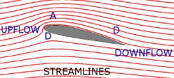 3.6.1 Lift generation In the 'Basic forces' module it was stated that when an aircraft is moving through the air, the consequent pressure changes or aerodynamic reactions to its motion will be acting at every location on its surface. We had a look at the formula for calculation of lift from the wings: (Equation #1.1) Lift [ newtons] = CL × ½rV² × S It is usual to substitute the symbol 'Q' to represent dynamic pressure [½rV²] so the expression above may be more simply presented as: (Equation #4.1) Lift [newtons] = CL × Q × S where Q × S is a force. It is appropriate to state here that the formula is an approximation of the average lift from the wings. At any one time, the aerodynamic reactions will vary over the span of the wing and with the position at which the wing control surfaces are set. Aerofoils and the aerodynamic force An aerofoil (airfoil, parafoil, wing section or wing profile) is an object — with the shape of the cross-section of the wing — having the function of producing a controllable net aerodynamic force by its motion through the air. To be useful this aerodynamic force must have a lifting component that is much greater than the resistance or drag component. In a powered aircraft, motion through the air is provided by the thrust; so in effect, the aerofoil is a device that converts thrust into lift; in a glider the aerofoil converts much of the gravitational force (the potential energy of height) into lift. The aerodynamic force has two sources: the frictional shear stress, or skin friction, that acts tangential to the surface at every point around the lifting body; and the pressure exerted perpendicular to the surface at every point. (At speeds over about 250 knots, flow compressibility introduces other factors.) The resultant net aerodynamic force is the sum of all those forces as distributed around the body. For wings, it is conventional to show the resultant force as acting from an aerodynamic centre and resolved into two components: that acting perpendicular to the flight path is the lift, and that acting parallel to the flight path is the drag. For propeller blades, the aerodynamic reaction is resolved into the thrust component and the propeller torque component. For rotor blades, a more complex resolution is necessary. Note: normally the aerofoil is incorporated into a wing with upper and lower surfaces enclosing the load bearing structure. However, when designing a low speed minimum aircraft such as the Wheeler Scout there are advantages in using a 'single surface' cambered aerofoil wing, very similar to a hang glider wing. Such wings incorporate a rounded leading edge (formed by the aluminium tubing leading edge main spar) that directs the airflow into the upper and lower streams at all angles of attack. The slight camber is formed by battens sewn into sleeves in the 'sails'. Such wings are somewhere between a thin curved plate and a full aerofoil, and are similar in cross-section to a bird's wing. A parachute wing uses the ram air principle to form the aerofoil shape — see 'The ram-air parachute wing'. Now we need to establish how that airflow actually produces the lifting force. John S Denker has published a web book 'See How it Flies' that has a particularly good section on lift generation with excellent illustrations. You should carefully read through section 3 'Airfoils and airflow' and particularly acquaint yourself with the Eulerian approach of 'streamlines' to visualise airflow. In the illustrative diagram at left, narrowing (A) of streamlines indicates accelerating local speed and decreasing local pressure — a favourable pressure gradient. Opening up (D) of streamlines indicates flow deceleration and increasing pressure — an adverse pressure gradient. The term 'free stream' is usually substituted for 'flight path' when discussing aerofoil characteristics because the aerofoil is presumed stationary, as in a wind-tunnel, and the airstream flows around it. The following summarises the content of section 3 of 'See How it Flies': • A flat plate, held at a small aoa, will generate an aerodynamic force — lift and drag — and indeed, some low momentum aircraft do use basically flat plates as their tailplane surfaces. As mentioned above, the shape of sail-type wings is somewhere between a plate and the more usual wing. However, for aircraft that cruise in the 50–150 knot range, a wing with a rounded leading edge, a sharp or square-cut trailing edge, a cambered upper surface and a flat or slightly cambered bottom surface — i.e. a full aerofoil section — will be far more efficient — aerodynamically and structurally — and more effective in performance. (The faster the aircraft, the more the aerofoil section tends to flatten out. So, for supersonic aircraft we are nearly back to the sharp-edged flat plate.) Aerofoil characteristics The straight line joining the leading edge (left) and trailing edge (right) is the chord line. The curved mean camber line is drawn equidistant between the top and bottom surfaces, and the light coloured gap between the chord and mean camber lines represents the camber — which, in this particular aerofoil [a NACA 4415], equates to 4% of the length of the chord at its maximum point which occurs at 40% of chord length from the leading edge. Aerofoil thickness is the distance between upper and lower surfaces. The maximum thickness of this aerofoil equals 15% of the chord; that is called the 'thickness ratio'. At the trailing edge the included angle between the upper and lower surfaces is significant in wake generation — a lower angle is better, and if the trailing edge is square-cut the thickness there should not exceed 0.5% of the chord. In flight, the angle the wing chord line subtends with the flight path is the geometric angle of attack. • A cambered wing will still produce lift at zero, and slightly negative, geometric angles of attack, as shown in the lift coefficient diagram. The aoa where no lift — only drag — is produced is called the zero-lift aoa which, in the diagram, is nearly –2°. From that diagram you can infer that camber contributes a lift coefficient of about 0.2 and anything greater must be provided by aoa. Of course, this will vary with the amount of camber in a particular aerofoil. If the aoa was reduced below the zero-lift value, for example –4°, then the direction of lift would be reversed. The only time you would need such a negative aoa is when you are flying inverted, or performing aerobatics, neither of which are currently allowable in aircraft registered with the RA-Aus. At the zero-lift aoa, all the aerodynamic force is acting parallel to the free stream and is mostly skin friction drag, with a less significant amount of pressure drag but the latter will increase as the aoa is increased. Pressure drag is explained in section 4.7 'Parasite drag'. Cambered wings perform quite well in inverted flight, but are not as efficient as in normal flight because a higher aoa is needed to make up for the lower wing surface having the maximum camber when inverted. For this reason, aerobatic aircraft tend to use symmetrically shaped aerofoils — i.e. the 'camber' of the bottom surface balances the 'camber' of the top surface and aerodynamically the result is zero camber — thus such wings rely purely on the geometric aoa to produce lift. • At positive angles of attack there is a stagnation point, or line, just under the leading edge of the aerofoil where some of the airflow has been brought to a standstill. The air molecules reaching that line, in the incoming stream, are equally likely to go under or over the wing. Stagnation pressure, the highest in the system, exists along the stagnation line. The location moves down and under the leading edge as aoa increases, up to the stalling aoa. Another more confined stagnation point exists at the trailing edge. If an imaginary line is drawn between the two stagnation points, the cross-sectional view of the division of the aerofoil into upper and lower flow areas becomes apparent. • The behaviour of the airstream flowing around such a wing accords with Bernoulli's principle. As the air accelerates away from the stagnation line, the local airflow over the upper surface gains a greater speed than the lower. Consequently, to retain constancy, the static pressure on the upper surface will decrease, and on the lower surface it may decrease very slightly at low aoa but will increase as aoa increases. There is another concept for explaining the pressure differential between upper and lower wing surfaces. Leonhard Euler was a mathematician who was a contemporary of, and collaborator with, Daniel Bernoulli. The Euler Equations (a special case of Newton's Third Law of Motion) express the relationship between flow velocity and the pressure fields in frictionless flow. Because the air particles follow the curved streamlines above the upper surface, there must be a centripetal force across the streamlines that accelerates the flow towards the centre of curvature. That force must be associated with a pressure gradient across the streamlines; i.e. ambient atmospheric pressure at some distance from the surface, grading to a lower pressure on the upper wing surface. For more information enter the terms 'Euler curvature airfoil OR aerofoil' into a search engine. • The usual way of looking at the lift force is that the wing produces an upflow in the air in front of it and a downwash behind it. That downwash continuously imparts momentum — with a downward velocity component — to the air affected by the passage of the aircraft. As you will recall from the 'Basic forces' module the action of adding downward momentum will have an equal and opposite reaction, which in this case is an upward force applied to the wing. And, of course, the energy provided to impart momentum to the air comes from engine power; in a glider it would come from the gravitational potential energy of height. There is a distinction between the 'downflow' produced by the aerofoil and the additional 'downwash' produced by wing vortices (see below), the deflection of which increases with angle of attack. However, for our purposes we can treat all the momentum imparted to the airstream as 'downwash'. You will also recall, from the 'Basic forces' module, that thrust is the reaction from the momentum imparted to a tube of air with the diameter of the propeller. The associated slipstream or 'prop wash' is the added momentum — quite apparent if you stand behind a stationary aircraft when 'running-up' the engine. Helicopter rotor blades are long, slender rotating wings — somewhere between variable pitch propeller blades and normal wings — and the momentum applied to the air — the 'rotor wash' — can be seen clearly by its effect on dust, vegetation and other objects (like parked ultralights) beneath a hovering helicopter. Similarly, a wing producing lift continuously accelerates a flattened tube of air with diameter approximating the wing span; the longitudinal downward inclination to the flight path of that flat tube increases as aoa increases. Some liken that concept to the wing acting as an airscoop. • Another concept associated with the aerodynamic force — circulation theory — is a mathematical description of a 'bound vortex', which also fits in with the generation of the physical wing-tip vortices. Vorticity is rotary motion in a fluid, and you could regard 'circulation' as referring to the apparent flow rotation — upwash then downwash — around the upper/lower surfaces. Note: there is a long-held and still-continuing argument, particularly in newsgroups and other internet venues, about the pros and cons of the various lift generation theories. None of the arguments put forward (often ill-informed) affect in any way how a light aircraft flies, how it should be safely and economically operated, or how it should be built; so it is best to ignore them unless you are particularly interested in the science of aerodynamics and skilled in mathematics. Pressure differential At any aoa between the zero lift and stalling angles, the total pressure pushing down on the wing upper surface will always be less than the total pressure pushing up on the lower surface. The absolute pressure difference between the upper and lower surfaces will increase as aoa increases up to the stalling aoa. Although it is still small in comparison with the ambient atmospheric pressure, it is this pressure differential resulting from the wing deflecting the air that initiates the lifting force; and this is true however lift theory may be expounded. Much work has been done in designing aerofoils that will maintain the required pressure difference in the targeted flight conditions. We can calculate the net pressure difference for the Jabiru using the scenario in the 'Basic forces' module section 1.4; i.e. cruising at 6500 feet, airspeed 97 knots or 50 m/s, air density 1.0 kg/m³. The ISA atmospheric pressure at 6500 feet is about 800 hPa: static pressure = 800 hPa dynamic pressure = Q = ½rV² = ½ × 1.0 × 50 × 50 = 1250 N/m² = 12.5 hPa Multiplying the dynamic pressure of 1250 N/m² by the lift coefficient of 0.4 gives the pressure differential of 500 N/m². That pressure differential of 500 N/m² (5 hPa) is less than 1% of the ambient static pressure, but applying that over the 8 m² of wing area gives the lift force of 4000 newtons that we calculated in section 1.4. Lift coefficient The lift coefficient CL is a dimensionless (or nondimensional) quantity (it has no units of measure) relating mostly to aoa. It increases as the aoa increases from the normal aoa used in cruise flight, and also to the form of the wing and the aerofoil section. CL represents the proportion of total dynamic pressure converted to lift force. When the aircraft designer calculates the CL curve for an aircraft it must be related to a particular wing reference area. This may be the visible plan area of the wings but it could also include that area of the wings conceptually enclosed within the fuselage. Note that the CL for an aerofoil will have a value perhaps 10–20% higher than the CL for any wing incorporating that aerofoil; this is discussed in the spanwise pressure gradient section. (The convention is to use a lower case 'L' [thus Cl ] when referring to the lift coefficient for an aerofoil to distinguish it from the lift coefficient for a wing, but I have retained CL for both.) In level, non-manoeuvring flight, lift equals weight, so equation 4.1 can be restated as: (Equation #4.2) CL = W / (Q × S) The usable value of CL in a very light aircraft with low-aspect ratio wings without lift-enhancing devices might range between 0.1 and 1.6. (Unless it is a symmetrical aerofoil — same camber top and bottom — the lift coefficient range will be different for the same wing when in inverted flight.) However, a very low CL value can be obtained momentarily if the wings are 'unloaded' in flight. This can be achieved by applying sufficient continuous forward pressure on the control column to attain a near-zero aoa such that the net pressure differential between the upper and lower wing surfaces is very low. This would imply low lift generation and reduced drag, so the thrust will accelerate the aircraft a little faster than normal. Furthermore, a negative CL can be obtained by maintaining so much forward pressure on the control column that the aerodynamic force is reversed. If initially flying straight and level, the aircraft will 'bunt'; i.e. enter the first few degrees of an outside loop with the centripetal force for the turn being supplied by the reversed lift. (This reverses the direction of the wing loading and should never be attempted in weight-shift aircraft nor three-axis aircraft unless the three-axis manufacturer's flight manual allows such a manoeuvre.) And, of course a suitably equipped aircraft can be flown in inverted level flight — in which case the under-wing surface becomes the upper and a completely different CL range applies, because the cambered surface is now underneath and a higher aoa is necessary to maintain the lift required for level flight. Incidentally many pilots utilise the low CL technique when landing a taildragger. The application of forward pressure on the control column after touchdown 'pegs' the aircraft down by reducing the aoa and thus generated lift, and thereby puts increased pressure on the tyres, and amplifies friction and any braking force applied. The same technique was used to bring military DC3 aircraft to a quick stop. 3.6.2 Aerofoil simulation Whichever way lift theory is expounded, this simple equation is applicable: Lift = CL × Q × S I suggest you try out what you have learned so far in an aerofoil flight test simulation program. You need a Java-enabled browser. Read the instructions carefully and reset the measurement units from pounds to newtons. In this case, airspeed will be shown in km/h but just mentally divide by two (and add 10%) to get knots — halve it again if you want m/s. You can try this simple model out with a popular aerofoil, the NACA 2412, which is one of a series dimensioned by the U.S. National Advisory Committee for Aeronautics (the forerunner of NASA) in the 1920s and 1930s. The 2-4-12 (twenty-four twelve) has a camber of 2% [2] of chord with maximum camber occurring at 40% [4] of chord from the leading edge and a thickness/chord ratio of 12% [12]. Note that all dimensions are proportional to the chord so the same aerofoil section shape is retained throughout a wing even if it is tapered in plan form. The wing is thickest at the root and thinnest at the tip; i.e. it must also be tapered in thickness. Most aerofoils suitable for light aircraft have a camber of 2–4%, thickness ratio of 12–15% and the maximum thickness (not camber) occurring at around 30% of chord. Now type the following data into the FoilSim boxes using the 'enter' key or use the sliders: Size: chord 1 m, span 8 m (area 8 m²) Shape: angle (of attack) 2°, camber 2%, thickness 12% Flight test: speed 166 km/h (90 knots), altitude 1947 m (6400 feet) Check the results displayed in the black boxes and in the plots. The static air pressure should be 80.0 kPa (800 hPa) and the lift is 4233 N. If you select 'surface pressure' from the output plots, you will see a plot of the pressure distribution across the chord for the upper (white line) and lower (yellow line) surfaces. Anything appearing above the green line (the atmospheric static pressure) can be regarded as a positive pressure pushing that surface at that point. Anything below the green line is a negative pressure pulling that surface at that point. The area between the two curves represents the magnitude of the differential pressure distribution. The horizontal axis indicates the percentage distance from the mid-chord position. The pressure gradient plot for the upper surface shows a maximum decrease of around 1.5 kPa (15 hPa) close to the leading edge but changing to a slight positive increase in pressure at the trailing edge. The pressure gradient plot for the lower surface shows an increase in pressure under the leading edge, quickly changing to a decreased pressure of a few hPa then back to a positive pressure from mid-chord back. If you press the 'Save Geom' button, a data table will be displayed showing the pressure and local velocity readings at 19 X-Y coordinate positions on both the upper and lower surfaces. If you now select 'surface velocity' for the output plot, you will see a plot of the local velocity distribution across the chord for the upper (white line) and lower (yellow line) surfaces. You can see that the local velocity increases to about 40% above the free stream velocity a very short distance downstream from the leading edge, then it gradually slows until local velocity is less than free stream velocity at the trailing edge. Now change the airspeed to 110 km/h (60 knots) and the aoa to 12°, and look at the surface pressure and surface velocity plots again. Note the big increase in local velocity that is now some 2.5 times the free stream velocity a very short distance downstream from the leading edge. Also note the big increase in the pressure differential and that most (about 70%) is occurring within the first 25% of the chord. You should do a little exploration starting with the aerofoil design, changing just one value at a time and noting the changes in the upper and lower pressure gradients. For instance change the camber from 2 to 4% (i.e. the NACA 4412 aerofoil) and see the lift generated increase to 6369 N with a CL now 0.74. You can do the same with the flight performance items under pilot control — aoa, altitude and airspeed. Of course, FoilSim doesn't provide any information concerning drag generation or pitching moment. 3.6.3 Boundary layer airflow In the following section I use the concept of the airstream flowing over a stationary wing (as in a wind tunnel experiment) rather than the reality of the aircraft moving through stationary air, for easier explanation. The innermost molecules of the moving air come into contact with the solid surface of the wing (and other parts of the aircraft) and are entrapped by the surface structure of the airframe materials. This is called the 'no-slip condition' and is common to all fluid flows. The interaction between those air molecules and the molecules of the solid surface transfers energy and momentum from the air molecules to the solid surface molecules — producing skin friction drag and shear stress that act tangentially to the surface. Those surface-interacting air molecules retreating from the surface consequently carry less momentum than they did on approach. In the very thin viscous sublayer adjacent to the solid surface, these molecules with reduced momentum move randomly into the fluid a small distance from the surface. The streamwise momentum per unit volume of the molecules that have interacted with the surface is less than the momentum a small distance from the surface. The random mixing of the two groups of molecules reduces the streamwise momentum of the molecules that have not directly interacted with the surface. This exchange of momentum between slower and faster molecules is the physical origin of air viscosity (the resistance to flow when a fluid is subject to shear stress) and of that viscous sublayer or boundary layer comprising the region between the wing surface and the unrestrained or inviscid outer stream. The diagram shows the velocity gradient within the boundary layer; the more turbulent the flow, the steeper the gradient and the greater the shear stress and friction. The atmospheric boundary layer is similar but, of course, on a grander scale. Laminar and turbulent flow The thickness of the boundary layer starts at zero at the wing leading edge stagnation point, but will increase (as an increasing number of molecules lose momentum) until a maximum thickness is reached near the trailing edge. The friction between air layers moving at different velocities within the boundary layer is generally weak, so the flow from the stagnation point is initially made up of smooth-flowing stream lines or laminae — laminar boundary layer flow. But on both the wing upper and lower surfaces not far downstream from the leading edge, the laminar flow, less than 1 mm in thickness, usually transitions to a flow with small irregular fluctuations — turbulent boundary layer flow — and continues to increase in thickness by around 1% of the distance travelled to a maximum near the trailing edge of perhaps 10–15 mm for a 1200 mm wing chord. Drag increases as the boundary layer thickens. The extent of laminar flow and thus the location of the transition zone — where boundary flow is a mix of laminar and turbulent — depends on the designed aerofoil shape in profile, the angle of attack, contour variations (ripples, waviness) formed during construction and service, the flexibility of the wing's skin, surface roughness/cleanliness, porosity, and the pressure gradient along the wing chord. In the area where the pressure gradient is favourable (i.e. decreasing, thus the flow is accelerating), laminar flow will tend to continue, though becoming thicker, unless something trips it into the more irregular turbulent boundary layer flow — even paint stripes can trip laminar flow. The laminae nearest the skin move slowly and cohesively, thus minimising skin friction drag. In the turbulent flow boundary layer, the air nearer the wing is moving faster and somewhat chaotically, thus greatly increasing skin friction drag. The transition zone tends to occur a particular distance downstream (for a combination of the preceding factors) rather than a percentage of chord even though the aerofoil might be designed for laminar flow for a particular percentage of chord. The aerofoils used for light aircraft wings have very little laminar flow. But specialised high-speed aerofoils are designed to promote laminar flow over perhaps the first 30–40% of the wing chord by providing a favourable pressure gradient for at least that distance (i.e. maximum thickness at 40–50% of chord) and a properly contoured, very smooth, clean, non-flexing, seamless skin. The latter conditions are also important for minimising the thickness of the turbulent boundary layer flow with consequent reduction in skin friction drag and are achievable in composite construction. Flow separation Generally at lower angles of attack, the boundary layer and the outer stream will separate (break away or detach) from the wing upper surface at the trailing edge or perhaps slightly upstream from the trailing edge, causing a thin trailing wake to form between the outer streams. As aoa increases past perhaps 12°, the boundary layer separation on the wing upper surface might tend to move upstream a little. But at the stalling aoa, separation will suddenly move much further upstream, and a thick turbulent wake will form between the two remnant boundary or shear layers and will be dragged along by the aircraft. The reaction to the wing accelerating and energising that previously stationary air is a sudden deceleration of the aircraft, accompanied by a sudden increase in the magnitude of the nose-down pitching moment. Downwash disappears and the rate of loss of lift will increase rapidly as the aircraft slows. Aerodynamicists devote much effort to controlling and energising the boundary layer flow to delay separation and thus allow flight at lower speeds; for example, see vortex generators. More lift and much less pressure drag is generated in attached turbulent boundary layer flow than in partially separated flow. 3.6.4 Aspect ratio Aspect ratio is the wing span divided by the mean wing chord. An aircraft with a rectangular wing of area 12 m² might have a wing span of 8 m and constant wing chord of 1.5 m. In this case the aspect ratio is 5.33. If the span was 12 m and the chord 1 m, then the aspect ratio would be 12. However because wings have varied plan forms, it is usual to express aspect ratio as: Aspect ratio = wing span² / wing area It is conventional to use the symbol 'b' to represent span, so the equation above is written as: (Equation #4.3) A = b² / S The Jabiru's aspect ratio (span 7.9 m, area 8.0 m²) = 7.9 × 7.9 / 8 = 7.8, whereas an aircraft like the Thruster would have an aspect ratio around 6. Consequently you would expect such an aircraft to induce much more drag at high angles of attack, and thus slow much more rapidly than the Jabiru. And incidently, the mean chord (not the mean aerodynamic chord) of a wing is span/aspect ratio. A high-performance sailplane wing designed for minimum induced drag over the CL range might have a wingspan of 22 m and an aspect ratio of 30, thus a mean chord of 0.7 m. There are a few ultralight aeroplanes, designed to have reasonable soaring capability, that have aspect ratios around 16–18, but most ultralights would have an aspect ratio between 5.5 and 8, and averaging 6.5. General aviation aircraft have an aspect ratio between 7 and 9, probably averaging around 7.5. Note that the higher the aspect ratio in powered aircraft, the more likely is wingtip damage on landing. Note that 'wing area' includes the nominal extension of the wing shape into and through the fuselage. This would appear quite apt for a parasol wing or a high-wing aircraft, but will no doubt seem odd for a mid or low wing. It is just a means for consistent application/comparison between aircraft designs. The span loading is the aircraft weight divided by the wingspan = W/b. The term sometimes refers to the loads applying at specified stations along the span. 3.6.5 Spanwise pressure gradient There is a positive spanwise pressure gradient (the rate of pressure change with distance) on the upper wing surface from the wing tip to the wing root, imparting an inward acceleration to the airflow close to and above the wing. Conversely, at other than a very small aoa, there is a positive underwing pressure gradient from the wing root to the wingtip, and airflow under the wing acquires an outward acceleration. These spanwise (or more correctly semi-spanwise) pressure gradients on the upper and lower surfaces are caused by the higher pressure air from the undersurface revolving around the wingtip into the lower pressure upper surface. This tip effect results in a near total loss of lift at the wingtip because of the reduced pressure differential, with the loss of pressure differential progressively decreasing with distance inboard. Where these two surface airflows with different spanwise velocities recombine past the trailing edge, they initiate a sheet of trailing vortices. These are weakest near the fuselage and strongest at the wingtips, and roll up into two large vortices, centred just inboard and aft of each wingtip. The vortices increase in magnitude as aoa and lift increase, and so increase the vertical component of, and the momentum imparted to, the downwash. As the centre of each vortex is a little inboard of the wingtip, the vortices also have the effect of reducing the effective wing span, the effective wing area and probably the effective aspect ratio. The vortices also affect the air ahead of the aircraft by reducing the magnitude of the upflow in front of the wing and thus modifying (decreasing) the effective wing aoa, with the greatest effect near the wing tip and little effect near the wing root. When a wing is at a low CL aoa the airstream affected by the wing has a slight downward flow. When it is at maximum CL aoa, that airstream has a more substantial downward flow contributed by the vortices. Because of the reduction in the effective aoa, the wing must fly at a greater aoa to achieve the same lift coefficient that a two-dimensional aerofoil will achieve in the laboratory. Also, the wing tip vortices have a decreasing effect with increasing aspect ratio. This is demonstrated in the diagram where there are three (exaggerated) CL and aoa curves plotted. On the left is the laboratory curve for an aerofoil, in the middle the curve for a high aspect ratio wing utilising the same aerofoil and the curve on the right is for a low aspect ratio version. The red horizontal line connects with a particular CL value, say 1.2. The vertical red lines indicate a different aoa for each curve at the same CL, thus the high aspect ratio wing must fly at a higher aoa and the low aspect ratio wing must fly at a still higher aoa for either to achieve CL 1.2. Or to put it another way, at any aoa the wings produce less lift than the laboratory aerofoil. Also apparent from the diagram is that a higher aspect ratio has the effect of a higher rate of lift increase, as aoa increases, than lower aspect ratio wings. A high aspect ratio wing will have a higher CLmax but a lower stalling aoa than a low aspect ratio wing utilising the same aerofoil. Induced drag has a direct relationship to aspect ratio; see section 4.6. Wing-tip vortices make up most of the wake turbulence created by an aircraft in flight and are certainly the most hazardous to following aircraft. They are usually referred to as wake vortices in the context of air traffic and are the same as other atmospheric vortices in that there is a central low pressure core that is often visible as condensation trails when an aircraft pulls higher g in a humid atmosphere. Read the New Zealand Civil Aviation Authorities booklet 'Wake Turbulence'. 3.6.6 Induced drag As explained in section 4.5 the effect of the vortices is to reduce the effective aoa of the wing compared to that of the laboratory aerofoil, which has the further effect of giving a more rearward inclination to the resultant aerodynamic force for the wing, compared to the aerofoil, at a particular geometric aoa. When that aerodynamic force is resolved into lift and drag components, the additional inclination will produce a reduced lift vector (apparent in the preceding CL/aoa diagram) and an increased drag vector. That increase in the drag vector is the induced drag. Induced drag is least at minimum aoa and greatest at maximum aoa. It is often said that the induced drag is the energy dissipated to induce lift; i.e. if CL is increased, induced drag increases, so thrust must be increased to provide additional energy — if the aircraft's flight path is to continue as before. For example, if the pilot wants to increase aoa and maintain the same airspeed (as in a constant rate level turn), then thrust must be increased to counter the increase in induced drag. There is a point in an aircraft's flight envelope where, because of the increasing induced drag, the slower you want to fly the greater the power you must apply — known as 'flying the back of the power curve' — which is opposite to the norm of applying power to fly faster. Elliptical lift force distribution As stated in section 4.5, with most wings — particularly rectangular wings — the higher pressure air underneath the wing flows around the wing tip into the lower pressure area above, thus reducing the pressure differential and the lift; the effect of this decreases as span and/or aspect ratio increase. Induced drag is minimised if the spanwise distribution of the lift forces can be made to present an elliptically shaped pattern, as shown in the diagram, and that aerodynamic load is equally distributed over the wing so that all areas of the wing contribute to load sharing. (This idealised lift force distribution diagram presents a head-on view of the whole wing without any representation of — or distortion by — the fuselage.) . Elliptical spanwise lift distribution will provide a desirable uniform downwash along the span, and can be achieved by choice of wing plan form and/or by twisting the wing to provide something near an elliptical distribution in a speed band selected by the designer. High aspect ratio elliptically shaped (in plan form) wings generally achieve spanwise elliptical lift distribution; however, because of the compound skin curvatures they are the most difficult and time-consuming to construct. Low aspect ratio constant chord (i.e. rectangular) wings without twist are the easiest to construct but generate the most induced drag; however, the introduction of twist makes such a wing much more efficient. Medium aspect ratio wings with a medium taper ratio plus twist are probably the most used shape. Taper ratio is the ratio of the tip chord to the wing root chord. 'Medium taper' would indicate that the tip chord is greater than 50% of the root chord. Sailplane designers have demonstrated that the most effective high aspect ratio wing is one that has a straight (i.e. non-tapered) trailing edge with a leading edge that is increasingly tapered in sections from root to tip. Wing twist or washout The terms 'wing twist' and 'washout' refer to wings designed so that the outboard sections have a lower incidence, 3–4° or so, and thus lower aoa than the inboard sections in all flight conditions. The main reason for wing twist is to reduce induced drag (see section 'Elliptical lift force distribution') and particularly so at a cruising angle of attack or perhaps the climb speed angle of attack. Another reason is to improve the stall characteristics of the wing so that flow separation begins near the wing roots and moves out towards the wingtips. With twist, the sections near the wing root reach the stalling aoa first, thus allowing effective aileron control even as the stall progresses from inboard to outboard. This is usually achieved by building geometric twist into the structure by rotating the trailing edge, so providing a gradual decrease in aoa from root to tip. Washout reduces the total lift capability a little but this disadvantage is more than offset by the wing twist improving elliptical lift distribution and thus decreasing induced drag. Another form of washout — aerodynamic twist — might be attained by using an aerofoil with a higher stalling aoa in the outboard wing sections. Aircraft incorporating washout tend to not drop a wing during an unaccelerated stall. Instead, there is a tendency to just 'mush' down sedately then drop the nose and regain flying speed. The turbulent wake from airflow separation starting at the wing root buffets the tailplane, thus providing some warning of the oncoming stall before it is fully developed. Also, washout is usually applied, for aerodynamic balance, to the swept wings utilised in weight-shift ultralights. However, geometric washout can cause problems at excessive speed. Effect of wing span/aspect ratio on induced drag The equation for calculating induced drag for a wing is: Induced drag = (k × CL² / A) × Q × S where A is the wing aspect ratio [b²/S] and k is related to a span effectiveness ratio. So, induced drag is directly proportional to CL² and inversely proportional to dynamic pressure [Q], and might comprise 50% of total drag at maximum angle of climb speeds. The lower the span loading [W/b](i.e. the greater the physical span or the 'effective' span), the lesser the induced drag at all angles of attack. This results in a decrease in the thrust needed, particularly for climb — or an increase in the potential energy of height for a sailplane. Various wingtip designs, such as Hoerner wingtips, have the effect of moving the vortices slightly further outboard, thereby increasing the effective span and thus reducing the span loading and induced drag. The information in the following box may only be of interest to aircraft homebuilders, so skip it if you wish and go to the next part . Aspect ratio equals b²/S (equation #4.2), so the equation above can be rewritten as: (Equation #4.4) Induced drag = (k × CL² × S / b²) × Q × S The factor k equals 1/Pe where P [pi] equals 3.14 and e is the span effectiveness factor that might vary between 0.7 and 0.9 for the aircraft as a whole. For an elliptic plan form wing, something like that of the near-elliptical wing of the Seafire 46 at left, with (theoretically) no fuselage interference, then e=1.0 and k =1/3.14 × 1.0 = 0.32. A non-twisted tapered wing will have a span effectiveness factor of perhaps 0.9, so induced drag will be 10% greater and greater still (+20%?) for a non-twisted rectangular wing. However, fuselage and fuselage junction interference will reduce the span effectiveness of the wing. Equation #4.2 states that CL = W / (Q × S). Substituting that for CL² in Equation #4.4: Induced drag = k × [W²/ (Q² × S²)] × (S / b²) × Q × S Some of the terms cancel out, leaving: (Equation #4.5) Induced drag = k × W² / (b² × Q) Equation #4.5 shows that induced drag is proportional to span loading squared [W²/b²] and inversely proportional to dynamic pressure [Q], so that two aircraft with quite different aspect ratios but having an identical span effectiveness factor, wing span and weight would produce the same induced drag at the same dynamic pressure (e.g. same density and TAS or lower density and higher TAS, etc). Anything done that gives a small increase in effective wing span will provide a proportionately higher reduction in induced drag. Jabiru induced drag calculation If we guess that the Jabiru aircraft span effectiveness factor is about 0.8, we have enough information to do a rough calculation of the induced drag on our Jabiru cruising at 97 knots at 6500 feet (as in the pressure differential calculation above). We will use a more practical form of induced drag equation for those who skipped the preceding box: Induced drag = k × CL² / A × ½rV² × S For the Jabiru, k = 1/(3.14 × 0.8)= 0.4, aspect ratio [A] is 7.8 and the CL at that speed is 0.4. = 0.4 × (0.4 × 0.4 / 7.8) × (0.5 × 1.0 × 50 × 50) × 8.0 = 0.4 × 0.02 × 1250 × 8 = 80 newtons If you repeat the CL calculation in section 1.4 using the Jabiru's stall speed at 6500 feet, say a TAS of 25 m/s, you will find that CLmax is 1.6. Now if you repeat the induced drag calculations, you will find it has increased fourfold: Induced drag = 0.4 × (1.6 × 1.6 / 7.8) × (0.5 × 1.0 × 25 × 25) × 8.0 = 0.4 × 0.33 × 312.5 × 8 = 330 newtons 3.6.7 Parasite drag Parasite drag is all the air resistance to a light aircraft in flight that is not considered as 'induced', and consists solely of pressure drag and skin friction drag; the latter is due to viscous flow and has been covered in the boundary layer air flow section above. The parasite drag constitutes much of the total aircraft drag at minimum aoa (i.e. high speed) but comparatively little at maximum aoa (minimum speed). Refer to the diagram in section 1.6. When associated with airflow around an aerofoil, the parasite drag is termed profile drag. Pressure drag or form drag is the net pressure differential of those points on the wing; for example, where a component of the pressure acts in the fore and aft direction, and that pressure differential tends to retard the aircraft. Pressure drag, like skin friction, applies to all parts of the aircraft 'wetted' by the airflow. It is greatest for any part of the airframe that presents a flat surface perpendicular to the flow and least for a streamlined shape that has a fineness ratio (i.e. length to breadth) between 3:1 and 4:1. The illustration — a cross-section of a 3:1 fineness ratio wing strut — shows the flow streamlines detaching from the surface close to the trailing edge, with the characteristic wake associated with pressure drag. What is not apparent from the illustration is that, in this instance, the skin friction drag would be significantly greater than the pressure drag There are two specially named classes of parasite drag: interference and cooling drag. Interference drag occurs at the junctions of airframe structures; for example, the junction of the wings and fuselage or the junction of the undercarriage legs and fuselage. The boundary and outer streamflows interfere with each other at the intersections and cause considerable turbulent drag. Interference drag for a well-designed composite aircraft might be 5–10% of total parasite drag but can be very much higher. The cross-flow associated with unbalanced flight (slip/skid) exacerbates interference drag. If interference drag potential is ignored by the designer, vortex development can occur at the wing/fuselage junctions, effectively splitting the spanwise lift distribution into two separate elliptical patterns; this is particularly so with low-wing configurations but not so much with high wings. The problem is minimised, and total parasite drag considerably decreased, by careful design to reduce the number of junctions, and to use fillets and fairing to direct a smooth airflow around the remainder. Usually the most visible evidence of an interference drag reduction program is the large wing root fillet used in low wing aircraft as seen in the AR-5 photograph. Engine cooling drag is normally associated with the cooling airflow for engines enclosed in a drag reducing cowling. The cooling airflow is designed to be efficiently directed from an air intake through a system of baffles for optimum engine cooling, and perhaps to utilise the energy of the added heat to provide a little thrust at the cowling exit point. Where the engine is not cowled, there is a great deal of parasite drag that certainly cools the engine but would not be specially classed as cooling drag. 3.6.8 Aircraft lift/drag ratio In unaccelerated straight and level flight, lift equals weight, and thus will be a constant value. If you look at the total drag diagram in section 1.6 you will see that the drag varies with the airspeed which means, of course, that it varies with angle of attack. The diagram on the left is a plot of the fixed lift value divided by the total drag value; i.e. the L/D ratio, at varying aoa for a reasonably efficient aircraft. It can be seen that L/D [L over D] improves rapidly between zero or negative aoa up to 4–5° then drops off until the stall angle, where the deterioration rate accelerates. Note that a non-aerobatic light aircraft in normal flight would not experience these low L/D values at aoa between 0° and 2°. The maximum L/D for light aeroplanes — a measure of the aerodynamic efficiency of the aircraft — is possibly between 8 and 12. Some of the ultralights designed with wide span, high aspect ratio wings to provide some soaring capability have a maximum L/D around 30. High-performance sailplanes that are built with very wide span, slender, high aspect ratio wings have the greatest L/D, at 40 –50, and thus the greatest efficiency. Powered parachutes have a L/D ratio around 3. There is a limit to the thrust that the engine/propeller can provide (i.e. the drag that it can match) thus there is also a minimum L/D at which maximum engine power is required to maintain constant altitude. Consequently, there will be a minimum aoa (maximum airspeed) and a maximum aoa (minimum airspeed) at which an aircraft can maintain level flight. As there may not be much range between minimum and maximum L/D, the minimum L/D can be quite significant for ultralight aircraft, where a range of engines, some with rather low power, may be utilised in the same model. An under-powered aircraft will perform very badly at the back of the power curve. Glide ratio Maximum L/D usually occurs at an angle of attack between 4° and 5°, or where the CL is around 0.6. This L/D ratio is also termed the glide ratio because it is just about the same ratio as distance covered/height lost in an engine-off glide. For example, if maximum L/D =12 then the glide ratio is 12:1, meaning the aircraft will glide a distance of 12 000 feet for each 1000 feet of height lost, in still air. We can use the '1-in-60' rule to calculate the angle of the glide path relative to the ground; for example: L/D = 12, then 60/12 = 5° glide path angle. If the aircraft is maintained in a glide at a degraded L/D, then the glide path will be steeper: L/D = 8, then 60/8 = 7.5° glide path angle. This is one effect of using flaps (see section 4.11). Be aware that quoted L/D ratios rarely take into account the considerable drag generated by a windmilling propeller. The aoa associated with maximum L/D decides the best engine-off glide speed [Vbg] for distance and the best speed for range [Vbr] according to the operating weight of the aircraft. But because of the flat shape of the curve around maximum L/D, these speeds are more akin to a small range of speeds rather than one particular speed. 3.6.9 Pitching moment When using the FoilSim aerofoil flight test simulation program, the static pressures around the aerofoil are given in the output plot that shows the pressure distribution pattern changing with the aoa. It is convenient to sum that distribution and represent it as one lift force vector acting from the centre of pressure [cp] of the aerofoil or wing for each aoa; much the same way as we sum the distribution of aircraft mass and represent it as one force acting through the centre of gravity. The plot on the left is a representation of the changing wing centre of pressure position with aoa. The cp position is measured as the distance from the leading edge expressed as a percentage of the chord. (Please note the diagram is not a representation of the pitching moment.) At small aoa (high cruise speed) the cp is located around 50% chord. As aoa increases (speed decreases) cp moves forward reaching its furthest forward position around 30% chord at 10–12° aoa, which is usually around the aoa for Vx, the best angle of climb speed. With further aoa increases, the cp now moves rearward; the rate of movement accelerates as the stalling aoa, about 16°, is passed. Most normal flight operations are conducted at angles between 3° and 12°, thus the cp is normally positioned between 30% and 40% of chord. The movement of the cp of the lift force changes the pitching moment of the wing, a rotational force applied about some reference point — the leading or trailing edges for example — which, in isolation, would result in a rotation about the aircraft's lateral axis. The consequence of the rotation is a further change in aoa and cp movement that, depending on the cp starting position may increase or decrease the rotation. Thus a wing by itself is inherently unstable and will change the aircraft's attitude in pitch — i.e. the aircraft's nose will rotate up or down about its lateral axis, which may be reinforced or countered by the action of the lift/weight couple — so there must be a reacting moment/balancing force built into the system provided by the horizontal stabiliser and its adjustable control surfaces. This will be discussed further in the Stability and Control modules. Aerodynamic centre There is a point on the wing's mean aerodynamic chord (see below) called the aerodynamic centre [ac] where the pitching moment coefficient [ Cmac ] about that point is small — for the NACA 2412 aerofoil Cmac is –0.1. The negative value indicates the moment produces a nose-down torque, which is the norm for cambered wings. Cmac remains more or less constant with aoa changes but becomes more nose-down at the stall. For the cambered aerofoils used in most light aircraft wings, that aerodynamic centre will be located in a position between 23% and 27% of the chord length aft of the leading edge, but for standardisation, aerodynamicists generally establish the lift, drag and pitching moment coefficients at the 25% (quarter) chord position. The notation for the pitching moment at quarter chord is Mc/4. The pitching moment is consistently nose-down, changing in magnitude as airspeed changes. When plotted on an aerofoil wind tunnel data graph, the moment coefficient Cmc/4 is a roughly horizontal line for most of the angle of attack range, but the straight line may have a slight slope if the actual aerodynamic centre varies a little from the 25% chord location. Pitching moment equation: (Equation #4.6) Pitching moment [ Mc/4 ] = Cmc/4 × ½rV² × S × c The pitching moment equation is much the same as the lift and drag equations with the addition of the mean aerodynamic chord [c] for the moment arm; using SI units the result is in N·m. As the coefficient is always negative and nearly constant (up to the stall), then V² is the significant contributor to the nose-down pitching torque, which must be offset by tailplane forces to keep the aircraft in balanced flight. However, high torsion loads may still exist within the wing structure; see aerodynamic effects of flight at excessive speed. The concept of the aerodynamic centre is useful to designer/builders, because it means the centre of application of lift can be assumed fixed at 25% chord and only the lift force changes. For non-rectangular wings, a mean aerodynamic chord [MAC] for the wing has to be calculated; see ascertaining mean aerodynamic chord graphically — in that diagram the aerodynamic centre position [ac] is shown on the root chord line. Neutral point It is not just the wings that produce lift, the tailplane surfaces also produce lift (which is discussed in module 6), and so do parts of a well-designed fuselage. Consequently the aerodynamic centre for the aircraft as a whole, known as the neutral point, will not be in the same location as the wing aerodynamic centre but — for a tailplane aircraft — behind it and on the fuselage centreline. This is the fixed point from which net lift, drag and aircraft pitching moment are assumed to act. 3.6.10 Ailerons We mentioned in section 1.4 that the pilot cannot change the shape of the wing aerofoil. But this, like many statements made regarding aeronautics, needs qualification. In fact, the pilot manoeuvres the aircraft in the lateral plane by altering the effective camber of the outboard sections of the wings. And remember in the last paragraphs of section 4.1 above, using FoilSim, we found that altering camber from 2% to 4% produced a substantial increase in CL and lift. If you examine the Seafire photograph, in section 4.6, you will see that each wing has a separated section at the outboard trailing edge. These are ailerons, hinged to the main wing so that they can move down or up and linked, via control rods or cables, to left/right movement of the pilot's control column. The control column is a simple lever which amplifies forces applied by the pilot. Thus the pilot can, in effect, increase or decrease the camber of the outer portion of each wing; as shown by the effective chord lines in figures A and B at left. The ailerons are interconnected so that downward movement — a camber increase — in one is combined with an upward movement — a camber 'reflex' — in the other. The aileron movement then increases the lift generated by the outer section of one wing whilst decreasing that from the other, thus the changed lift forces (at a distance from the aircraft's longitudinal axis) impart a rolling moment in the lateral plane about that axis. This rolling moment is primarily used to initiate a turn but other manoeuvres depend on the amount and timing of aileron movement; more about this in the 'Control' module; see 'Control in a turn'. Ailerons span perhaps the outer 35% of each wing and occupy perhaps the aft 20% of the wing chord at that location. High-speed aircraft may have two sets: a normal outer wing set used only for low-speed flight (because of the moment of force they are capable of applying at high speed) and a second, high-speed set of spoiler-type ailerons located at the inboard end of the wing. Aileron drag Increasing camber and thus CL also increases induced drag (in proportion to CL²) so that the wing that is producing greater lift will also be producing greater induced drag, tending to rotate (yaw) the aircraft's nose in the direction of the lowered aileron. Parasite drag will be increased on the wing with the lowered aileron. This induced plus parasite drag reaction is called aileron drag and particularly complicates aileron effects at low speeds when CL is high, the aerodynamic pressure on control surfaces is low, and it is easy to impart an excessive control movement. Because the yaw is towards the lowered aileron and thus opposite to the required direction of turn, the effect is called adverse yaw and is particularly evident in aircraft that have long-span wings where the ailerons have a much longer moment arm. Aileron drag can have an opposite yaw effect. When an aircraft is turning at low speed and the pilot applies aileron to roll upright, the downwards movement of the aileron on the lower wing might take the aoa, on that part of the wing, past the critical aoa. Thus that section of wing — rather than increasing lift and making the wing rise — will stall and lose lift. The aircraft, instead of straightening up, will roll into a steeper bank. Although the wing section may be stalled, CL and thus induced drag will still be fairly high, so there will be a substantial yaw toward the lower wing which pulls the nose down and increases the rate of descent. There is potential for other aileron-induced problems when turning at low speeds; see 'Control in a turn'. There are a number of configurations which, used singly or jointly, reduce aileron drag. For example, differential ailerons, where the down-going aileron moves through a smaller angle than the up-going aileron or Frise ailerons, where the leading edge of the up-going aileron protrudes below the wing undersurface, increasing parasite drag on the down-going wing. 3.6.11 Flaps The other camber increasing devices, forming part of the inboard wing trailing edge in the Seafire photo, are the flaps. Plain flaps are also a hinged section of the wing — as in figures C and D in the aileron diagram above — but move only (and jointly) downward usually to fixed predetermined positions, each position providing varying degrees of increased lift coefficient and increased drag coefficient that the designer thought appropriate. For instance, for one particular aircraft, at 5° deflection there is a good increase in CL with only slight increase in drag. At 15° the drag increase starts to equate with the increase in the CL, whereas at 25° or 30° the increase in drag is much greater than the increase in CL; at 45° the flap is starting to act as an airbrake. The change in camber (over perhaps 50–60% of the wing span and 20–25% of the wing chord) caused by lowering flaps in flight, without changing other control positions, has effects which will vary according to the amount of deflection employed: The aircraft's nose will pitch down a few degrees about its lateral axis (i.e. its attitude in pitch is altered) because of the nose-down pitching moment associated with flaps. The position of the aircraft's line of drag will change and this also tends to change the aircraft's attitude in pitch. Depending on the relative mounting of the aircraft's wings and tailplane, the change of direction (and the increase) of downwash may affect the trim of the aircraft — nose up or down. The lift increases and the aircraft will initially tend to rise. The drag increases and the aircraft slows below its trimmed airspeed, lift reduces, and the aircraft sinks unless power is increased. The pilot has to take appropriate control action depending on the reason for lowering flaps. The effects of trim associated with lowering or raising flaps for a particular aircraft type will be noted in the Pilot's Operating Handbook. As we saw in FoilSim, the effect of increasing camber is an increase in CL (the ratio of lift to dynamic pressure or airspeed) at all aoa. This is shown in the plot at the left. At an aoa of 6° CL is about 1.0 with flaps lowered — about 50% greater than the CL of 0.65 with flaps raised. What this means is that the minimum controllable flight speed is lower with flaps deployed. So, returning to the equation: lift = CL × ½rV² × S thus for lift to remain constant if CL increases then V² must decrease. Consequently, the stall speed is also lower with flaps deployed. (Incidently, this diagram shows that the zero lift aoa for this wing occurs at –2°.) Note that the flapped section will stall at a lower aoa than the unflapped section. Generally the flapped wing area, being the inboard section of the wing, represents a very large proportion of the total wing area — check the Seafire photo. Also, even if the flapped section has passed its stalling angle, it is still producing lots of lift. Providing there is sufficient thrust available to overcome the big increase in drag, the aircraft can still maintain height and stability because the wing outboard section and ailerons are not stalled. Bear in mind that to maintain the same airspeed and altitude after lowering flaps, that thrust, if available, must be increased to counter the additional drag from the lowered flaps. Similarly, when flaps are raised, the aircraft will initially sink due to the loss of lift unless the pilot takes compensating control action; this is particularly important when a landing approach is discontinued and a go-around initiated. Now what aoa are we measuring? If you look at figure C (in the drawing in section 4.10) which represents the unflapped part of the wing, you can see that it has an aoa of about 5° or so whereas, at the same time, the flap extended section of wing (figure D) has a considerably greater aoa. As the flapped section will still have a stalling aoa around 16° we can surmise that this flapped wing section is going to stall when the unflapped section is only at 13° or so. (The horizontal axis of the plot shows only the aoa of the unflapped wing.) However, we also have to take into account the increased downwash and thus the change in effective aoa associated with it, so the effect of flaps is not as straight-forward as implied in the preceding. Flap systems There are a many types of flap systems, but if flaps are used at all in ultralights or other very light aircraft, then only the simpler devices shown at left are needed. The most common (because of its simplicity) is the plain flap, which might provide a 0.5 increase in CLmax with a large increase in drag when fully deflected. The split flap provides slightly more increase in lift but a larger increase in drag, and is more difficult to construct and thus probably not worth the effort. The slot incorporated into the junction between the main wing and the plain flap in the slotted flap arrangement allows airflow from under the wing to energise (i.e. accelerate and smooth) the turbulent boundary layer flow over the upper surface of the lowered flap. This provides better downstream boundary layer adherence, and thus allows a larger angle of attack to be achieved before stall, with higher CL and lower drag than the plain flap. Ailerons may also be 'slotted' for improved performance. The rearward extension of the Fowler flap as it is deflected increases wing area as well as camber, so it provides the best increase in lift of all the simpler systems — although perhaps even a single-element Fowler flap like that shown is not that simple to construct. Summary — flap effect on coefficient of lift In the diagram above, it can be seen that the deflection of flaps provides an increase in CL of about 0.4 at all angles of attack. This is probably representative of plain flaps extending along 50% of the wing trailing edge with chord equivalent to about 20% of the wing chord, and deflected 25°. The attainable CL increase depends on flap span, chord and degrees deflected, plus the complexity of the flap system — CL increase of 0.8 might be achieved with long-span Fowler flaps deflected to 35°. Incorporating slots into plain or Fowler flaps increases CL. Advantages of using flaps If flaps are fitted, a small flap deflection — say 10° — might be used for safer take-off, due to the lower lift-off speed available. But half to full flap deflection is always used for landing to provide: lower safe approach and touch-down speeds a nose-down attitude for a better view of the landing area a steeper approach path (because of the degraded L/D) for better obstacle clearance, which can be controlled at will a shorter 'float' after rounding out because of increased drag a shorter ground roll, if flaps are left fully extended until the aircraft has exited the runway. And flaps enable the approach to be made with engine power well above idle, which is beneficial to the engine, allows power changes to either increase or decrease the rate of sink and provides better engine response in case of a go-around. Flaperons In some light aircraft designs, particularly those with short take-off and landing [STOL] capability, it has been found expedient to incorporate the aileron and a plain flap into one control surface that extends the full length of the wing trailing edge. The different functional movements are sorted out by a control mixer mechanism. Usually, the flaperon is not integral with the wing but bracketed to the underwing to provide a slotted flap — acting like an external aerofoil flying in close formation with the main wing. Although the CL increase attainable might be 1.0, there are drawbacks to this arrangement, which particularly exacerbate low speed aileron drag. Reflex flaps Some aircraft are fitted with flaps that also can be deflected upward 5° or 10° above the normal neutral or stowed position in addition to the normal downward deflection positions described above. Upward deflection of flaps is done at cruising speed, and increases the maximum cruise speed perhaps 5% by reflexing camber and reducing drag, and is often associated with aerofoils that have good laminar flow. 3.6.12 High-lift devices Another short take-off and landing [STOL] device used in light aircraft is an aerofoil section — a slat — fixed to the leading edge of the wing, with a slot between the slat and the wing. The slat/slot works in much the same way as the slotted flap except that leading edge slats induce a nose-up pitching moment. At low aoa, the fixed slat has no value; it just increases drag and thus degrades cruise performance. At high aoa, the higher pressure on the underside of the slat is channelled through the slot, gaining velocity and energising the boundary layer flow over the upper surface of the wing — thus delaying boundary layer separation, adding perhaps a 0.6 CL increase and increasing the stalling aoa to perhaps 20°. The usual increase in CL and the stalling aoa is illustrated with the green curves in the CL/aoa diagram above. Some slat/slot systems also have the effect of increasing wing area thus reducing W/S and stall speed. Leading edge slots combined with long-span slotted flaps, as used in STOL aircraft, allow a critical aoa much greater than the usual 16°. They can perhaps double the maximum CL of the basic wing, which allows much lower landing speeds but requires flight at the back of the power curve. Fixed leading edge slots work particularly well with a tailwheel configuration in a 'utility' aircraft such as the Slepcev Storch, but in a touring aircraft they have no value unless the pilot intends operating into very small, rough airstrips. There are simple automatic slat/slot systems where the slat is stowed when flying at lower angles of attack but pops out to form the slot when a particular angle of attack is reached. There are also retractable slat/slot systems that provide STOL capability when required without sacrificing cruise performance, except for the weight increase due to the more complex operating system. I suggest now you have a look at the diagrams in Anatomy of a STOL aircraft. 3.6.13 Lift spoilers and airbrakes The converse of the high-lift devices is the light aircraft spoiler, common in gliders but occasionally seen in high L/D ratio ultralights. The usual spoiler is a flush-mounted front-hinged spring-loaded flat plate incorporated into the upper wing surface, which can be elevated by lever operation to varying degrees of opening. When activated, it induces separation over part of the wing, thereby acting as a lift-dumper. But it is not speed limiting; the nose will pitch down and the pilot must use elevator to maintain the required approach speed; thus the spoiler is used to increase the sink rate on the approach path. Airbrakes or speedbrakes have a similar but more effective function. They are often vertically mounted plates, pairs of which are incorporated into the wing structure and which protrude from the upper and lower wing surfaces when activated. They create a lot of drag but little or no change in pitch, so the pilot must lower the nose to maintain approach speed. Airbrake or spoiler configurations are sometimes associated with flap systems that are primarily directed to lift generation, rather than lift generation plus drag creation. Such flap systems would have maximum downward deflection of perhaps 20°. Military aircraft utilise very complex flaperon/spoileron systems. Things that are handy to know The aerofoil is often referred to as a 'two-dimensional' object. This means that that the spanwise — thus 'third-dimensional' — pressure gradient effects associated with a normal wing, and varying significantly with the wing form rather than the aerofoil shape, are ignored when considering aerofoil characteristics. Wing upflow: all the air disturbances caused by the passage of an aircraft are propagated as pressure pulses moving outward (from molecule to molecule) in all directions at the speed of sound. Thus, in subsonic flight, the pressure variances (compression then relaxation) contribute to the air upflow occurring in front of the wings. In sport and recreational aviation the term aircraft is a generic covering all types of aerial (airborne) vehicles; it includes 'lighter-than-air' (aerostats) and 'heavier-than-air' (aerodynes) but not vehicles that derive their lift from air reaction with the surface, e.g. hovercraft. The aerostats include hot-air balloons and power-driven hot-air airships, both deriving lift from buoyancy. The aerodynes derive their lift from the aerodynamic reactions described above and are in two classes — rotary-wing (rotorcraft) and fixed-wing. Rotorcraft are represented by helicopters, gyroplanes and the towed gyrogliders or rotor-kites. The fixed-wing aerodynes may be power-driven or unpowered, the latter represented by the various glider classes — sailplanes, hang gliders, paragliders and the towed parasails or para-kites. The power-driven aerodynes are represented by three groups: the weight-shift controlled trikes, powered parachutes, powered hang gliders and powered paragliders. the 3-axis controlled power-assisted sailplanes and motor-gliders and finally the ubiquitous 3-axis controlled aeroplanes. For more information see sport and recreational aircraft categories. Notes for homebuilders • The parasite drag coefficient. The equation for calculation of the total parasite drag for an aircraft is: Parasite drag [newtons] = CDp × ½rV² × S Unlike the lift coefficient, the parasite drag coefficient CDp is more or less a constant — the ratio of drag to dynamic pressure — and thus provides a means for comparing the relative aerodynamic 'cleanness' of two aircraft. The coefficient is usually in the range 0.03 to 0.08 for fixed-undercarriage aircraft. • There is another value, the 'equivalent flat plate area' [FPA] used by aircraft, motor vehicle and structural engineers who are concerned with the calculation of air resistance. FPA is often quoted in aviation magazines when comparing the parasite drag efficiency of an aircraft with other similar aircraft, and it is usually stated in terms of square feet. FPA is calculated as CDp times the wing area divided by the CDp for a flat plate. However, it is assumed that the CDp for a flat plate held at 90° to the airstream = 1 (in fact it is about 20% greater, but that is of no real consequence) so the flat plate CDp is omitted from the calculation, thus: FPA = CDp × S ft² For example, the FPA for the run-of-the-mill two or four-seater fixed-undercarriage general aviation aircraft would be around 6 ft² with CDp of 0.03 to 0.05, and the retractables around 4–5 ft² with CDp of 0.02 to 0.03. FPA of a very clean, high-performance general aviation aircraft like a Mooney model, is around 3 ft² with CDp about 0.015. Some very clean, high-performance GA kit-built aircraft have FPA less than 2. Note that FPA does not represent the frontal cross-section area of the aircraft. One of the smallest known FPA is not associated with a general aviation aircraft but with an owner-designed and built ultralight! Californian Mike Arnold's 65 hp two-stroke Rotax 582 powered AR-5 held the world speed record, in the under 300 kg FAI efficiency Class C1-A/0 of 213 mph in August 1992. This handsome little glass-epoxy aircraft has an FPA of 0.88 ft² with CDp about 0.016. It demonstrates the efficiency that can be achieved — an unmatchable 3.3 mph per hp — in an ultralight design when the home designer/builder pays the utmost attention to detail. Note the drag reduction achieved by the beautifully shaped engine cowling, the wing root fillet and the minimisation of the junctions of undercarriage leg fairing and wheel cover. The choice of a fibreglass/foam lay-up composite structure also facilitates the drag reduction program. Don't let anyone tell you ultralights have to be slow and draggy! • 'Separation bubbles' or 'laminar flow separation bubbles'. In laminar flow, sometimes the laminar flow boundary layer separates from the wing surface then reattaches itself a short distance downstream. This forms a 'bubble' of stagnant air with a significant spanwise dimension that changes the aerodynamic thickness of the wing which, in effect, increases pressure drag. Bubbles may also cause increased turbulent flow to be generated downstream of the reattachment point. Aircraft designers avoid laminar separation at cruising speeds by inducing a turbulent — but attached — boundary layer where necessary. Separation bubbles that increase drag may also occur on the fuselage and tailplane. See vortex generators below. • Reynolds number. Occasionally, in reference to boundary layer laminar to turbulent flow and flow separation characteristics you may see mention of the critical Reynolds number [Re]. Re is a measure of the relative influence of viscous and inertia effects on boundary layer behaviour. Like aspect ratio Re is a dimensionless quantity, i.e. it has no units of measurement. For rough estimates Re in airstreams = air density/air viscosity × airflow velocity × flow distance. ISA sea-level density is 1.225 kg/m³ and standard viscosity is 0.0000179 kg/m/s, so standard air density/air viscosity = 68 459 (say 70 000). If the Re is estimated for an average flow across the entire wing at a particular airspeed, then the equation can be simplified to: Re = velocity (m/s) × the mean aerodynamic chord (m) × 70 000. Thus, the wing chord Reynolds number for an aircraft with a MAC of 1.2 m flying at 97 knots (50 m/s) is roughly 50 × 1.2 × 70 000 = 4 200 000. When that same aircraft is cruising at 78 knots (40 m/s), Re would be about 3 360 000. For a particular wing and wing surface condition, there is a critical boundary layer Re, above which the laminar flow will transition to turbulent flow. In slow flight speed, the critical boundary layer Re will be attained a particular distance downstream from the leading edge stagnation point; as airspeed increases (and in accordance with the equation above), that distance must shorten. • The vortex generators [VGs] used in a few light aircraft designs, particularly short take-off and landing [STOL] aircraft — or as post-delivery 'add-ons' — are small boundary layer control devices with a swept-back leading edge and a vertical trailing edge, the chord at the base of the device is two to four times its height. VGs are machined from an aluminium 'T' extrusion or formed in polycarbonate, a row of 10 or 15 of which are usually spaced along the upper surface of each wing, probably close to the transition zone. Each VG is carefully sited, with a specific angle of attack (perhaps 15° or more) to the local airflow and with sufficient height to just intrude into the free-stream flow. So situated, they induce fast-rotating, highly organised, downstream vortices (much the same principle as wingtip vortices) which mix the high-speed free-stream airflow into the slow-moving, surface boundary layer flow; entraining and re-energising that flow so that the chordwise pressure gradient profile on the upper surface is decreased (see boundary layer flow). Consequently, surface pressure is decreased, so the pressure differential — and thus the lift coefficient — is increased at all wing aoas. VGs are often paired, to produce counter-rotating vortices. The VGs also delay boundary layer flow separation at high aoa; i.e. VGs lower the stall speed while improving the aircraft's low-speed behaviour. But there is likely to be minimum warning of onset of the stall, and stall behaviour may be more violent. Appropriately sized and sited wing vortex generators can be effective at providing good manoeuvring control of the aircraft when operating low and slow, and provide a greater CLmax, and improve aileron performance and aircraft climb performance. They are sometimes also used on the horizontal and vertical stabilisers mounted just forward of the rudder/elevator hinge lines where they have the effect of allowing greater control surface deflection before separation occurs. VGs are also useful in locations where interference drag is a problem. The use of VGs in light aircraft may slightly degrade performance at the upper end of the speed range, probably depending on the amount of additional turbulence they generate outside the normal turbulent boundary flow. • The term burble is sometimes used to describe a turbulent stream. For example a disturbance emanating from something on the fuselage can induce a turbulent streamflow that affects the tailplane. There may also be a separation of flow at the junctions of structural components, which causes interference drag. STRICT COPYRIGHT JOHN BRANDON AND RECREATIONAL FLYING (.com)

