
Admin
-
Posts
9,306 -
Joined
-
Last visited
-
Days Won
109
Content Type
Profiles
Forums
Gallery
Downloads
Blogs
Events
Store
Aircraft
Resources
Tutorials
Articles
Classifieds
Movies
Books
Community Map
Quizzes
Videos Directory
Everything posted by Admin
-
Please be advised that the user Flying Binghi has been given a week suspension from use of the site as several previous warnings have not been adhered to
-

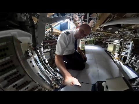
Showing Some Fancy Secrets Of The Magnificent Airbus 350
Admin posted a video in Commercial Aircraft
-
I did several very large updates on Clear Prop today...can you advise what the problem is
-
Rotax engines banned from use in military drones
Admin replied to JG3's topic in US/Canada General Discussion
If there isn't one you can always create one -
Rotax engines banned from use in military drones
Admin replied to JG3's topic in US/Canada General Discussion
Political natured posts have been deleted... -
Trump wanted his personal pilot to head FAA
Admin replied to red750's topic in US/Canada General Discussion
Please continue this discussion over on the Social Australia site https://www.socialaustralia.com.au/ -
Trump wanted his personal pilot to head FAA
Admin replied to red750's topic in US/Canada General Discussion
Guys. I really don't see this discussion continuing on the subject of aviation and I don't think it is going to end well...so I think I should close the topic but I will just see in the very very short term if I am incorrect...thanks for your views and contributions -
Emergency landing at Sydney beach
Admin replied to planedriver's topic in Aircraft Incidents and Accidents
I always believed that a baby could be carried as a 3rd person as long as it was on the lap and does not interfere with controls. If I also believed that I can certainly understand the pilot having the same belief and most probable thousands of other pilots. Now, for tongue in cheek, the courts recognise a life (or a recognised person) as being a 22 week fetus so does that mean that a pregnant woman of greater than 22 weeks also can not be a pax? I think a bit of common sense and understanding should go out to the pilot especially when you consider what he has gone through and the fear he must have felt to have both his wife and especially his 1 year old child with him. Well done to the pilot! -
Yes, the post was removed due to several complaints. Please read the site rules
-
Fantastic contribution @AT3 pilot thanks very much, especially what you felt you learnt from this very unfortunate event...but great to know you are still here with us
-
Thread closed
-
Thread closed
-
Enough, we are here to discuss between us good people, not inflame. A Pen Name 2 weeks cooling off
-
Safety wire. Where do you guys buy it from?
Admin replied to danny_galaga's topic in Aircraft Building and Design Discussion
I don't understand why some of you guys don't support our own pilot supplies shop Clear Prop, it's in the menu...it is also what helps to pay the costs of providing this site for you -
I urge anyone who feels that a post is not appropriate to click the 3 dots in the top right hand corner of the post and then click Report. This alerts the moderators to the post for them to act accordingly.
-
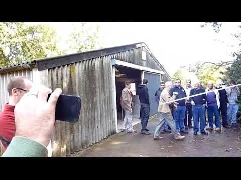 Ken Wallis MBE.Flies his AutoGyro for WMFC.
 -
Works ok for me on several devices, NBN and mobile
-
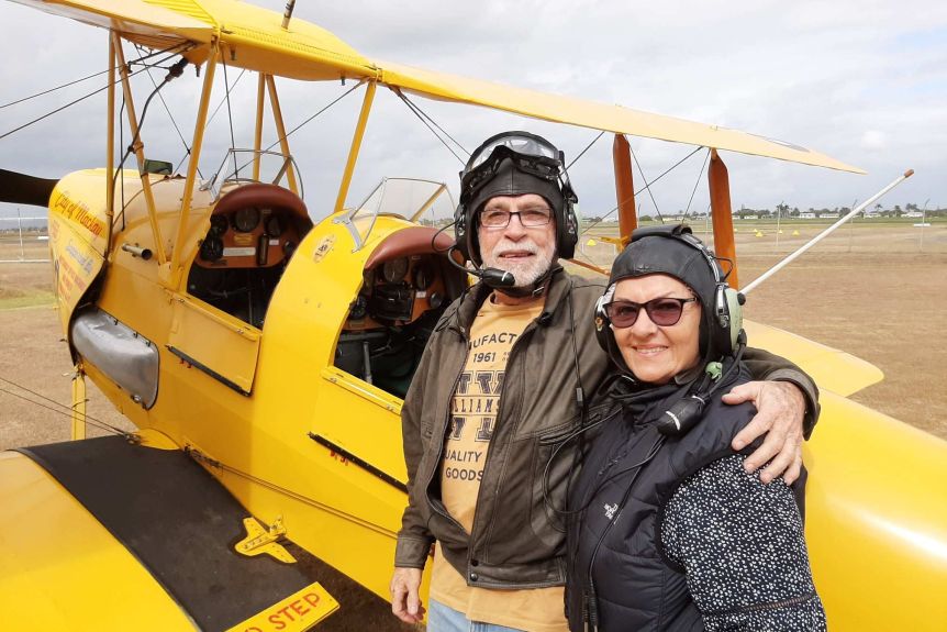 Tucked away inside a small north Queensland hangar are two planes that belong to a bygone era, flown by men with a deep appreciation of the past. With their bright retro colours and open cockpits, the World War II-era Tiger Moth biplanes almost look out of place in modern-day Mackay. They have been kept in pristine condition by the sons of Fred Christiansen, who once used them to ready fighter pilots for combat. Before and after the war, Mr Christensen worked in the sugar cane industry around Mackay, and he eventually settled in the "sugar city". He also passed on his love of flying to his two sons. One of them, Greg Christensen, 69, a founder of the Mackay Tiger Moth Museum and himself a pilot, recently reluctantly hung up his pilot's cap and goggles. But he's urging others to get involved, saying it's important to many descendants of local war veterans to preserve these moving memories of their past. "There's other blokes that are quite a bit older — a couple of guys are in their 70s," he said. "That is the only volunteer-based museum [housing Tiger Moths] where there's no profit going to... the pilots and the ground crew." As well as preserving the air crafts and their history, the Mackay Tiger Moth Museum has given passengers a unique glimpse of Mackay through an open cockpit.(Supplied: Mackay Tiger Moth Museum) WWII training aircraft The De Havilland Tiger Moth was first manufactured in the United Kingdom in 1931. During World War II, Tiger Moths were used as military training aircraft in Commonwealth countries, including Australia. According to the Royal Australian Navy, almost 1,100 of the planes were build in Australia between 1940 and 1945. The two Tiger Moths were purchased by the museum in the 1970s, to prevent them being sold overseas. The Tiger Moth Museum has been run by volunteer crew and pilots for decades.(Supplied: Mackay Tiger Moth Museum) Mr Christensen flew them for about 40 years. "My father was an instructor during the war, teaching people to fly in Tiger Moths. "My brother... was our first chief pilot and he taught most of us to fly the Tiger Moths." Mr Christensen completed his last flight in recent months, before moving south to be with family. "I did in excess of 1,500 joy flights around the town, so I got to see a fair bit," he said. He made sure his final passenger was someone special. "My wife was onboard. [She] was looking after the kids while I was playing with those things. It was quite nostalgic," he said. WWII descendants among museum pilots The Tiger Moths have been a common sight in Mackay's skies for more than 40 years.(Supplied: Mackay Tiger Moth Museum) Many volunteers and pilots at the Mackay Tiger Moth Museum are descendants of WWII veterans. Mr Christensen now hopes younger pilots will step up to the controls. "The aeroplanes are in great nick...[they] will outlast the people," he said. "It'd be great to see the younger people get enthused and get as much out of it as we have. One of the museum's Tiger Moths was built in 1943 and the other in 1942. Both have undergone expensive repairs and refurbishments over the years. The team of volunteers sells joyrides, with the proceeds invested in maintenance of the planes. Mr Christensen said the historic aircraft had long surpassed people's expectations and would still be gracing Mackay's skies for a long time to come. "They were supposed to go five years. That's what their life expectancy was," he said. "They'll go on forever."
 -
French Gendarmerie Helicopter in Chamonix Rescues Skier
Admin posted a video in Rotary Wing Aircraft
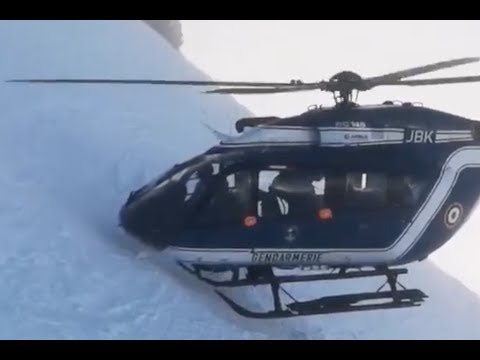 French Gendarmerie helicopter in Chamonix rescues injured skier from snow covered mountain with Eurocopter EC145. Helicopter performs maneuver 'appui patin' to land on the snow covered mountain with blades close to the mountain side to drop off and pick up crew. Pilot has over 5000 hours of flight time.
 -
Don't forget to add any movies into the site's movie section https://www.recreationalflying.com/movies/
-
 Seb Toro came to Australia to make his dream of becoming a pilot come true, but after years of classes with Soar Aviation he has little to show for it other than a $77,000 debt. His aim of getting his commercial pilot’s licence is nowhere nearer, in a similar story for many previous Soar Aviation students. Students have been stranded with Soar Aviation, one of Australia’s biggest flight schools, placed in administration. Mr Toro said he called it quits with the flight school after growing increasingly concerned about safety and teaching standards, after witnessing a dangerous crash that almost claimed the life of a fellow student in 2019. “The crash happened right in front of the window where we were studying,” he said. “It was a really bad situation. A poor pilot student who was in that horrible situation, it was lucky he survived.” The student at the flight school was left trapped after being involved in a serious crash at Moorabbin Airport on December 12 2019, that saw his plane flip and crash. A finding into the crash is yet to be handed down by the Australian Transport Safety Bureau, but it came after another serious crash of a student at Stawell in Victoria in October 2018. The ATSB found the 2018 crash was caused after “contrary to the aircraft’s limitations and the pilot’s qualifications, aerobatic manoeuvres were conducted during the flight, and immediately prior to the loss of control”. “Aerobatic flight should not be undertaken by pilots who have not been adequately trained, as it requires specialist techniques and methods to maintain control of the aircraft during significant manoeuvring,” investigators noted. “This accident clearly demonstrates the catastrophic consequences when the hazards of aerobatic flight are not managed.” More recently, a student and a trainer from the school died in a crash at Carcoar, south of Orange in the central west of NSW, in November in an attempt at a touch-and-go landing. Mr Toro said he was concerned about the instructors at Soar Aviation who were “very new to the industry”. “I still remember having one instructor from New Zealand, he got lost when we went for a flight,” he said. “I was a student and I ended up guiding the situation.” Mr Toro said the issues at Soar Aviation extended to its planes. “Some students had technical issues, one had a door open mid-flight,” he said. “They got planes that were for sporting. The planes were not designed for training purposes. Soar Aviation has 56 planes, but put up seven for sale in 2020 seeking to cover $500,000 in losses. Figures in the flight teaching industry said many of the planes used by Soar Aviation were considerably cheaper to operate than the Cessna 172 Mr Toro said the students saw advertised. Soar Aviation’s business model was built around providing part-time pilot training to students through its education partners in Sydney and Melbourne. Students were covered by VET-fee help for up to 200 hours of flight time, but anything extra was out of pocket for students. Its deal with the Box Hill Institute at one stage saw it teaching hundreds of students, but by the time it shut near the end of 2020 it had been whittled down to just 126 students. This is fewer than the almost 200 students currently members of a class action headed by Gordon Legal, alleging that the flight school did not meet CASA requirements, and delivered substandard teaching. Mr Toro said he was concerned that Soar Aviation kept trying to keep students flying despite them failing to progress to licences. “My problems started with getting massive overrunning hours without seeing a light to get my licence,” he said. “Management was pushing its instructors to push people to fly no matter the weather. “The extra repetitions that was the big concern for us, if you run out of your 200 hours the extra hours were out of pocket.” Mr Toro said he signed up to Soar Aviation because the offer to study part-time meant he was able to continue working. He was quickly concerned about the “very poor student support” and how few people were able to progress to a commercial pilot licence. “The internal exams were so easy to pass, but the ones that really mattered were the ones by the Civil Aviation Safety Authority,” he said. “The majority of students failed to comply with CASA regulations because of the poor quality theory training.” Mr Toro said he and fellow students had brought up issues with Soar’s former CEO, Neel Khokhani, and its education partner, the Box Hill Institute. “I had a very stressful meeting with the Dean of aviation. He said you can drop the course and nothing more happens,” Mr Toro said. Mr Toro said Mr Khokhani was mostly absent during his time at Soar Aviation, speaking to his class once. Mr Khokhani declined to comment.
 -
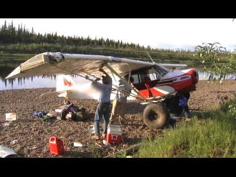 This is footage that was included in the bonus section of Big Rocks and Long Props Volume 2. It was shot before I had my HD camera so over 12 years ago not sure how long ago it was as time has a way of blurring together.
 -
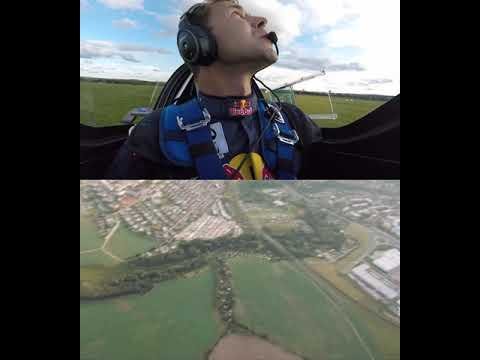 Aerobatic pilot Martin Sonka performs a stunning trick with a Red Bull can. He drops it from his aerobatic EXTRA 300 SR flying high above the clouds and during it´s free fall he managed to quickly descend and land, get out of the airplane and catch the can still falling from the sky in his hands.
 -
nice light suitable personal logbook, suggestions ?
Admin replied to RFguy's topic in Student Pilot & Further Learning
We have one either black or Pink and is lightweight but comprehensive here in the site shop https://www.clearprop.com.au/for-pilots/other-pilot-supplies/pilot-log-book-black-or-pink/ -
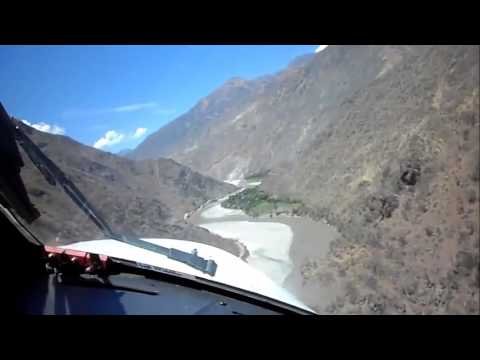 Chagual (SPGL), Peru proves to have one of the most impressive approaches in the world. S7°47.85' / W77°39.09' Elevation: 3967.0 feet MSL Dimensions: 3937 x 59 feet / 1200 x 18 meters Runway 14/32


