Admin
-
Posts
9,302 -
Joined
-
Last visited
-
Days Won
109
Content Type
Profiles
Forums
Gallery
Downloads
Blogs
Events
Store
Aircraft
Resources
Tutorials
Articles
Classifieds
Movies
Books
Community Map
Quizzes
Videos Directory
Everything posted by Admin
-
Ok, @Ahmed Zayed is getting better so he has adjusted the listing of the leaders in the Quizzes to only show the top 3. I will also allocate more time per quiz...unfortunately once a quiz starts I can't change the allocated time. Hope this is ok?
-
What about if it just showed the top 3
-
I see that 5 have taken the first quiz, i would very much like to know how you found the new quiz section. There are some things that I can change with it like: Display x number of users that got the top results Display CORRECT ANSWERS on your Quiz results Allow users to play the quiz only once or many times (top results show only a user's first attempt or their highest attempt) etc So please let me know how you found the new quiz section and anything you think I need to change...thanks
-
In line with the objectives of this site: Increase pilot safety by increasing their knowledge of flying Increase pilot skills by the exchange of experiences through discussion In crease pilots knowledge in proper aircraft maintenance I have implemented a Quiz section to the site. Now this is just experimental at this stage with just 1 quiz being created. Subject to your feedback I may change some of the parameters of the quiz section before I add many more quizzes that I have ready to add to this new section so please, take the first quiz and let me know your feedback. Remember the quizzes are purely a learning tool in the hope they help and that THEY ARE FUN You can find them under "Resources" in the main menu Enjoy!
-
- One Right Answer
- 5 minutes
- 21 Questions
- Top 3 Players
This quiz contains basic questions as an introduction to flight -
 One of the world's rarest planes has made its final flight, touching down in a western Victorian town that fundraised for two years to bring it home. The Australian-made Wirraway was used to train pilots at the Nhill airbase during World War II. At its peak, there were as many Royal Australian Air Force personnel at the airbase as the population of Nhill. Today the population of Nhill, which is halfway between Melbourne and Adelaide, is about the same at just 2,000. The plane is made up of parts from countless discarded Wirraways, and is among the best preserved in the world. Aircraft engineer Borg Sorensen spent 10 years scouring the country for the parts, and another eight putting the pieces back together. He found his first Wirraway in Horsham, an hour from Nhill, hacked apart with an axe and spread over five paddocks. The Wirraway is welcomed by a large crowd at the Nhill Aerodrome.(ABC TV) Community funding brings plane home On Saturday Mr Sorensen flew the historic aircraft for the last time, from Frankston to the Nhill Aerodrome. "It was the first production-built aeroplane in Australia," Mr Sorensen said. "I wanted it preserved. I built it to preserve a Wirraway because there are not many left." The Wirraway was used to train Royal Australian Air Force pilots at the Nhill airbase during World War II.(Supplied: Nhill Aviation Heritage Centre) The community met its $300,000 fundraising target just hours before the plane touched down. Nhill Aviation Heritage Centre president Rob Lynch said the support for the project had been unprecedented. The project is entirely community funded. Weeks out from the landing an anonymous donation of $15,000 was received. It is hoped having the aircraft at the base will help commemorate the men who trained at Nhill and died at war. Construction underway at the Royal Australian Air Force Base at Nhill in 1941.(Supplied: Nhill Aviation Heritage Centre) Mr Sorensen could have sold his Wirraway for almost twice as much on the international market, but he knew it belonged at Nhill. "We'd been flying it for 16 years, my son and I, and we started going round doing airshows and then all of a sudden I thought 'That's really not what I built it for'," he said. "My reason for building it was to preserve it and when they put it to me, would I consider selling it, I thought 'Yes, that will just suit me fine'." Max Carland flew Wirraways during his training in the air force.(ABC Western Vic: Jessica Black) 'Amazing to see the thing still working' Max Carland flew fighter planes in New Guinea in World War II and came of fighting age with the Nhill airbase on his doorstep. "Most of the people at Nhill joined the air force because there was an air force stationed here," he said. "Having flown the Wirraway during my training days, it's amazing to see the thing still working." But the Wirraway was not without its faults. "Another thing it used to do that we didn't like very much was it used to, on starting, sometimes the engine would catch alight, so every time we started a Wirraway engine, we had to have a big fire extinguisher." Merv Schneider was a radio navigator and trained at the Nhill airbase before he was old enough to serve. "Our fighter pilots were Wirraway-trained. Being built in Australia, the opportunity of one coming home to Nhill really brings home the significance of the Wirraway."
 -
@Ahmed Zayed who helps with the development of this site and strongly note how much great work Ahmed has done for us all here, is currently quarantined in his home in Egypt without his family and doing it tough with positive Covid-19. Not sure how he caught it, Ahmed is a high level technician at a world renowned electronics company and Egypt doesn't have the strict work and social constraints that we have had here, especially here in Victoria so like any of us, it can be caught simply by standing in line for a coffee. I personally, and I am sure everyone here wishes Ahmed a speedy recovery and happy times once again with his family when he comes out of this hard time...get well Ahmed, stay strong and remember you will come through this
- 1 reply
-
- 14
-

-

-
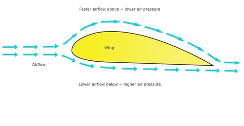
 Pitot tubes are crucial components onboard aircraft used to measure a range of important data. The tubes are popularly known as speedometers, giving pilots a gauge on their airspeed, and also measure altitude and altitude trend. Pitot tubes are usually found along the front fuselage or along the wing of an aircraft. What exactly are pitot tubes? Pitot tubes aren’t just inventions innovated for aviation; they’re also commonly found in industrial machinery, boats and even Formula 1 cars. A pitot tube is essentially a flow sensor instrument. Simple pitot tubes have one hole at the front; however, planes will often use pitot-static tubes with two openings rather than separate pitot tubes and static ports. Pitot-static instrumentation on an aircraft. Photo: Getty Images A simple pitot tube can measure stagnation pressure only due to its single opening. The advantage of a pitot-static tube is its ability to measure static pressure in addition to stagnation pressure. Static ports along the side of the pitot tube give it this all-in-one capability, meaning there is no need to install separate static ports elsewhere. How pitot tubes work Pitot tubes work as flow sensors to measure the speed and pressure of air, liquid or gas. These readings allow pilots to gauge airspeed and altitude and have a wide variety of applications in other equipment. The tubes can usually be spotted beneath the cockpit on the front fuselage or along the wing. Pitot tubes clearly visible on a 737NG. Photo: Simple Flying/Dylan Ashe The pitot-static tube has two openings, one in the front and one along the sides, used to measure air, gas or liquid flow. This system involves placing a pitot tube inside another tube with static ports. The front hole measures the stagnation pressure, while the side openings (static ports) gauge static pressure. The difference between these two measurements is called dynamic pressure – this is what is used to calculate airspeed. Pitot tubes are critical instruments Measuring airspeed is an indispensable part of flying and essential for all pilots to keep a gauge of. Pitot tubes provide indicated airspeed (IAS), based upon measuring the dynamic pressure. This is different from groundspeed, as planes can encounter resistance during flight, such as headwind and air density. Pitot tubes provide pilots with vital data on airspeed and altitude. Photo: Getty Images Planes flying too slowly won’t generate enough lift and risk spiraling into a stall, while aircraft flying too quickly risk damage as they aren’t built to withstand certain speeds. Airspeed is also vital in estimating flight length – inaccurate estimations may cause pilots to run out of fuel mid-journey if the flight goes on longer than expected. Incidents involving pitot tubes As a critical part of an aircraft’s instrumentation, pitot tubes have been at the center of several accidents. As the tubes are exposed to the elements, they are in danger of icing over, which has led to several fatal accidents. Pitot tube failures will always force a plane to divert – in October, an Airbus flight over Russia was forced to land after its pitot tubes were not heating up adequately. Testing the pitot-static system is important for ensuring safety. Photo: Lufthansa In one case, wasps nested inside a pitot tube, which later led to a fatal crash onboard Birgenair Flight 301. The aircraft had been grounded for 20 days and its pitot tubes were left uncovered, allowing wasps to burrow inside. Australia is to this day combating nuisance wasps that are nesting inside pitot tubes. Another high-profile case involved a disgruntled American Airlines mechanic tampering with a pitot tube, which led to an emergency landing.
 -
Yes, there could be separate What's New pages however there would be a slight performance hit in that the SQL Query that pulls the data up from the database for each one would have to include specific forum criteria (forum list filter)
-
The Off Topic site Social Australia is used to direct off topic discussions away from this site Recreational Flying however I have to make a choice between 3 options in the next few days and need you to advise on what you want. The Off Topic site uses the same software as this site, that is IPS and in the next few days the software license will expire. Now the site is just used as a secondary site, produces no income and simply costs. To renew the IPS license will cost around $400USD a year. This option will keep it looking and working like this site. I could go to the Xenforo software at only $200USD per year but whilst it would be cheaper, it would look and work differently than this site. The last option would be to bring the Off Topic back into this site. The cost is nil but it would be hard to completely segregate the Off Topic threads and posts from the aviation ones. So please vote on what you would like to have.
-

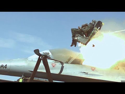 An ejection seat is a system used to rescue the pilot of an airplane in an emergency. Usually, the seat is propelled from the plane by explosives or rockets. Once off the plane, the ejection seat's descend is controlled by using a parachute. Here is a video showing an ejection seat test mission conducted by the USAF. There are very few missions requiring years of planning and preparation, only to be accomplished in less than six seconds. There are even fewer facilities where such a mission can take place. The Holloman High Speed Test Track (HHSTT) is a facility that enables test scientists and engineers to meet both of the above criteria. Tests on the track provide data on problems that cannot be solved by other ground test means. The tests are conducted by securing the ejection seat to a rocket-propelled sled and launching the sled to a speed identical to that of which a pilot will encounter in an actual flight.
 -
 It’s no secret that aviation is one of the biggest contributors to the planet’s carbon deposits. If left unchecked, research shows that aircrafts will have generated over 43 metric gigatons of carbon emissions by 2050. The same study notes that aviation is also one of the fastest-growing sources of carbon in the US. In order to create a more sustainable industry, local aeronautics specialists are doubling their efforts to make flight more eco-friendly. One solution they found, of course, was to switch planes’ fuel motors with electrically charged ones. For years, the venture seemed fruitless—but NASA is proving that nothing is impossible. The X-57 Maxwell is NASA’s first fully electric experimental aircraft. It was first released as a concept last year, but the government agency is conducting its first tests this month. Powered by two 400-pound lithium-ion battery packs, the X-57 Maxwell skilfully addresses the biggest hurdle faced by electric-powered aircraft: weight. Innovative propeller technology An aircraft is very heavy, which is why it takes a lot of energy to keep it in the sky. Yet, on the flip side, the majority of a plane’s weight is the machinery that powers the aircraft. Due to an increase in accessibility of “light yet reliable” high-lift motors and motor controllers, NASA has been able to solve the weight issue. Electronic manufacturers were able to calculate their PCBs’ stackup impedance to ensure enough signal layers in every power path. As a result, all the machine’s components get enough electricity between the ground and power planes, enabling each motor to work with minimal sag or droop. On each of X-57 Maxwell’s wings, six of those electric-powered motors are built-in for each propeller, theoretically allowing the plane to fly. An ultra-light aircraft NASA didn’t actually build the X-57 Maxwell’s body. The base used was a Tecnam P2006T—an aircraft built by Costruzioni Aeronautiche Tecnam from Italy. This plane continues to be the lightest twin-engine aircraft available, which made it the best starting point for NASA’s aircraft. Furthermore, the X-57 Maxwell’s wings are at least 58% smaller than regular wings. NASA claims that not only will this reduce the overall weight, but also lower the drag. This will prevent the aircraft from expending too much power. Where is the X-57 Maxwell now? NASA recently completed the plane’s Low-Speed Aeroacoustic Wind Tunnel (LSAWT) in Hampton, Virginia. They exposed the hardware to wind speeds from zero to over 90 knots for 14 hours. The results were very positive. The LSAWT test took over two weeks during October. “The X-57 project is using these tests to determine the as-built performance versus our models, so that we have high confidence in the performance of these propellers when we get to flight,” mentions Nick Borer, Advanced Concepts Group Lead for NASA Langley’s Aeronautics Systems Analysis Branch. Once the X-57 Maxwell successfully takes off, it’s going to be proof that zero-emission air travel is possible. NASA just needs to perform a couple of other tests and we’ll hopefully see the aircraft in the sky in the near future. Indeed, the future is bright for sustainable aviation.
 -
A PILOT was “shaken up” after his light aircraft suffered engine failure and was forced to crash land soon after take-off at Tyabb airfield. The Searey amphibious single-engine plane was reported to have landed on the emergency east-west runway where it collided with a parked twin-engine Cessna 414, 10.30am, Wednesday 25 November. Peninsula Aero Club president Jack Vevers said the plane was in the air for about eight seconds after reaching a height of “maybe 50 feet”. The pilot was taken to Frankston Hospital with a sore back and for a general assessment. An Australian Transport Safety Bureau spokesman said the bureau would not be conducting a safety investigation into the incident as “doing so would be unlikely to uncover new safety issues or learnings”. Mr Vevers said the PAC would be conducting its own inquiry. He estimated the damage bill to be around $20,000.
-
Negligence vs Insurance where does this leave us
Admin replied to graham brown's topic in AUS/NZ General Discussion
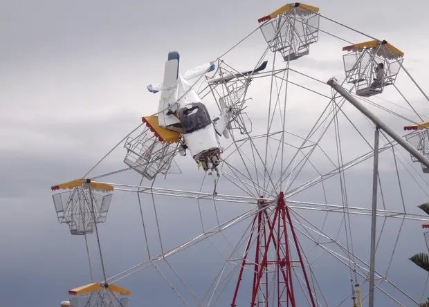
Amber Christine Arndell was just 13 when a light plane crashed into the ferris wheel set up next to an airstrip on the mid-north coast The light plane that crashed into a ferris wheel at a fair at Old Bar Beach near Taree in 2011. Amber Christine Arndell, who was on the ride, has been awarded her $1.5m in damages. Photograph: Frank Palfreyman/AAP A young woman who was on a ferris wheel when it was struck by a light plane has been awarded $1.5m in damages by a New South Wales court which heard she was “unemployable” almost 10 years after the traumatic event. Amber Christine Arndell, then 13, and her brother were riding the 20 metre-high amusement at the annual Old Bar Beach festival near Taree in October 2011 when a two-seat light plane took off at an adjacent airstrip. The aircraft attempted a landing before taking off again, veering left into the ferris wheel. The NSW supreme court this week found MidCoast Council and pilot Paul Clarendon Cox negligent for breaching their care to the woman. “[Arndell’s] evidence makes clear she was frightened the ferris wheel was going to collapse and/or the fuel from the plane would ignite – and that she and her brother would die,” Justice Stephen Rothman said this week. Cox was ordered to cover 35% of the $1.5m in damages. He failed in his lawsuit against the council despite the court accepting the pilot had suffered insomnia, flashbacks and other mental harm due to the crash. His landing attempt that turned into touch-and-go “displayed a lack of due care and diligence”, the judge said. The court heard a council officer had examined the ferris wheel after it was erected and raised no issues with its placement. That was despite it intruding into the splay – a three-dimensional area meant to remain clear to allow aircraft to land and take off. Two medical experts agreed Arndell’s experience of the collision was traumatic and had significant effects but were split on whether the trauma had been resolved and what effect earlier, traumatic events had on her recognised psychiatric illness. The court heard the woman had ridden on another ferris wheel after the crash. She testified that occurred under pressure from her grandparents to face her problems and she was shaking and in tears during it. Arndell was unable to attend fairgrounds and ride on a ferris wheel again until 2017 when accompanied by her partner. The judge concluded she had a pre-existing psychological vulnerability, went through a period of decompensation and developed a generalised anxiety disorder and a major depressive disorder. “The overwhelming cause of the plaintiff’s incapacity is the trauma associated with the collision,” he said. Her school reports had spoken of a hard-working and confident student until late 2011 and it wasn’t unreasonable to expect that Arndell would have completed high school and worked in the fashion industry, the judge said. The collision had made that an “impossible task” and – while not fully restricting her enjoyment of life outside work – it was “clear that for all practical purposes the plaintiff is unemployable,” the judge said. Arndell, now 23, was awarded slightly under $1.1m for lost wages. Her non-economic loss was deemed to be worthy of a $412,200 payment. Source: https://www.theguardian.com/australia-news/2020/dec/02/woman-awarded-15m-in-damages-after-ferris-wheel-struck-by-plane-in-nsw
-
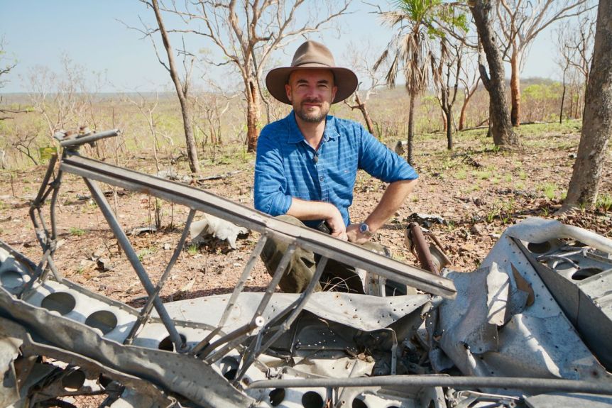 On June 30, 1943, Flight Sergeant Colin Duncan and his squadron of Spitfires took off on a mission to intercept Japanese aircraft over Darwin. But while the ensuing battle has for decades been marked in folklore, the whereabouts of Duncan's shot-down plane has, until now, remained a mystery. The Spitfire A58-2 Duncan was flying caught fire, engulfing the cabin in flames and sending the aircraft plummeting towards the ground in a spiral dive. Desperate to escape, the rip cord to release his aircraft canopy failed, leaving Duncan scrambling to force it off and struggle out of the aircraft to parachute to the ground. Flight Sergeant Colin Duncan defied death to make it back to Darwin.(Supplied: Australian War Memorial) But his battle was only just beginning. Duncan was stranded with severe burns in tough Top End terrain, alone and with minimal supplies, and it would be another five days before he was rescued. Bombing of Darwin: 70 years on On February 19, 1942, Japanese forces launched air raids on Darwin. Hundreds were killed in the attack. This compilation of videos, pictures and recollections take a look a of the most significant moments in Australian history. Seventy-six years since that fateful flight, Colin Duncan's grandson has visited the wreckage of his grandfather's plane for the first time. As he walked through the untouched debris of the Spitfire's final resting place, Duncan Williams was left shocked. "It's a genuine time capsule," he said. "I didn't expect it. I don't know what I was expecting really. Mr Williams said he was amazed his grandfather managed to escape alive. On viewing the wreckage, he remarked on how the Spitfire hit the ground with such force it left only a mangled mess of metal. "He was very lucky to get out alive," Mr Williams said. "Here we've got the cannons. You can see the angle the plane hit the ground. The aircraft wreck is now protected under the Northern Territory Heritage Act.(ABC News: Ian Redfearn) The remote location in Litchfield National Park, about 110 kilometres south of Darwin, means the Spitfire has remained undiscovered until recently. And with the crash site immensely difficult to reach and only accessible by helicopter, the plan is to preserve the wreckage at its final resting place. 'This is our Pearl Harbour' The RAAF has handed ownership of the wreckage to the Northern Territory Government in the hope it will help tell the story of Darwin's role in World War II. According to RAAF Air Commodore John Meier, the new find in the Top End outback is testament to the Darwin's often forgotten place in modern wartime history. Hundreds were killed in air battles over Darwin during World War II.(ABC News: Ian Redfearn) "We only had a few Spitfires in Australia, and this one is of major significance because it was lost in the battle of Darwin," he said. "If you compare it to Pearl Harbour, that everyone knows about, this is our Pearl Harbour, and it's not particularly well known by the Australian population." Colin Duncan continued flying Spitfires in the war, and later played cricket for Victoria as well as running a successful building company. He died in 1992 from cancer, leaving behind his wife and two daughters.
 -
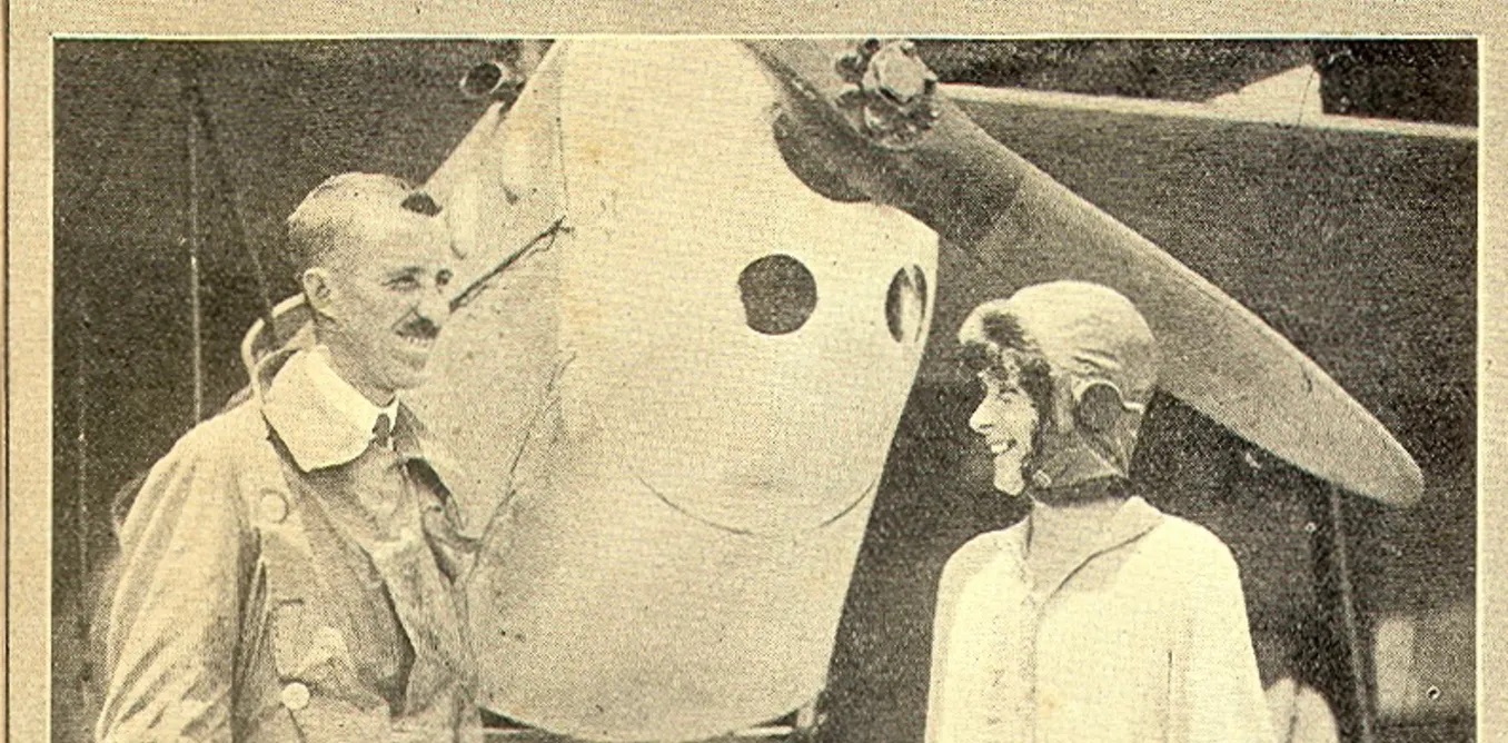 Before the glamorous flyers of the 1930s like Amelia Earhart, “Chubby” Miller and Nancy Bird Walton, another woman opened the way to the skies — and were it not for a tragic twist of fate, her name might now be just as familiar. Her name was Millicent Maude Bryant, and in early 1927, she became the first woman to gain a pilot’s licence in Australia. She was also first in the Commonwealth outside Britain. Millicent Bryant c.1919. Portrait by Monte Luke. Author provided A boundary-pusher who met an untimely end Millicent was born in 1878 at Oberon and grew up near Trangi in western New South Wales. Her family, the Harveys, moved to Manly for a period after a younger brother, George, contracted polio (one of the treatments was “sea-bathing”). She met and married a public servant 15 years her senior, Edward Bryant. They had three children but the couple separated not long before Edward died in 1926. Later that year, Bryant began instruction with the Australian Aero Club at Mascot in Sydney. At the time, the site of the current international airport was just a large, grassy expanse with a few buildings and hangars. Bryant was accepted by the Aero Club’s chief instructor, Captain Edward Leggatt (himself a noted first world war fighter pilot), soon after the club had opened its membership to women. Even then, though, she was unusual: here was a 49-year-old mother of three taking up the challenge of flying which, in the 1920’s, was still as dangerous as it was exciting and glamorous. Millicent Bryant (second from left) with other aviators beside her De Havilland Moth. Author provided courtesy of Mary Taguchi. She quickly progressed, ahead of two other younger, women students, and made her first solo flight in February, 1927. By this time, newspapers all around Australia were following her story, and in late March she took the test for the “A” licence that would enable her to independently fly De Havilland Moth biplanes. She passed, and with the issue of her licence by the Ministry of Defence, Bryant was acclaimed as the first woman to gain a pilot’s licence in Australia. Millicent Bryant’s training certificate from the Aero Club of Australia (NSW Section). Her ‘A’ Licence was issued by the Department of Defence in April, 1927 Why, then, isn’t she better known in our day? While Bryant immediately began training for a licence to carry passengers and flew regularly in the months that followed, it was her particular misfortune to step onto the Sydney ferry Greycliffe on its regular 4.14pm run to Watson’s Bay on November 3, 1927. Less than an hour later, she was among 40 dead after the ferry was cut in half off Bradley’s Head by the mail steamer Tahiti. It was Sydney’s worst peacetime maritime disaster. Bryant was still only 49. Her funeral two days later was attended by hundreds of people and accorded a remarkable aerial tribute, as the Wellington Times reported: Five aeroplanes from the Mascot aerodrome flew over the procession as it wended its way to the cemetery. As the burial service was read by the Rev. A. R. Ebbs, rector of St. Matthew’s, Manly, one of the planes descended to within about 150 feet of the grave, and there was dropped from it a wreath of red carnations and blue delphiniums … Attached to the floral tribute was a card bearing the following inscription: 5th November, 1927. With the deepest sympathy of the committee and members of the Australian Aero Club — N.S.W. section. A pioneer in life as well as the sky Bryant’s story quickly lapsed into obscurity. Fortunately, some 80 years later, the rediscovery in the family of a collection of letters and other writings has enabled Bryant’s life beyond her flying achievement to be rediscovered. The letters were — and are still until they are added to the collection of Bryant’s papers in the National Library — held by her granddaughter, Millicent Jones of Kendall, NSW, who rediscovered them in storage at her home. The main correspondence is a conversation with her second son, John, in England. It covers the period she was flying, though it only moderately expands on the flights recorded in her logbook. However, her letters and writings reveal much more about Bryant herself, her relationships, her feelings and her leisure, business and political activities. And they make it apparent that she was as much a pioneer in life as well as in the sky. A clipping from The Bulletin, February 24, 1927. The Bulletin., Author provided For one, flying was not Bryant’s only unconventional interest. She was also an entrepreneur, registering an importing company in partnership with John, who went on to become a pioneer of the Australian dairy industry. She opened a men’s clothing business, Chesterfield Men’s Mercery, in Sydney’s CBD. However, disaster struck when it was inundated with water mere weeks after opening, following a fire in the tea rooms upstairs. Bryant then became a small-scale property developer, buying and building on land in Vaucluse and Edgecliffe. She’d been well tutored in this by her father, grazier Edmund Harvey (a grandfather of billionaire Gerry Harvey), whose own holdings eventually included a large part of the Kanimbla Valley west of the Blue Mountains. An excellent horsewoman, Bryant was also an early motorist who had driven over 35,000 miles around NSW and who could fix her own car. She was a keen golfer and reader and even a student of Japanese at the University of Sydney. A key writing fragment by Millicent Bryant (c.1924). Author provided Several fragments of a family saga she planned to write, based on her own life, are among her papers. One sheet, entitled “A Life”, summarises in a series of rough notes rather more than she might have told anyone about her inner world. Marriage – mistakes – children – despondency. Ill-health. Great desire to “live” and create things… She notes that a trip abroad was a complete success but it furnished a heart interest which lasted for fourteen years until hope died owing to a marriage. This fragment provides some background to her taking, in her forties, the unusual step at that time of leaving her marriage and family home to start life afresh with her sons. This was not long before she took her first flight, probably with Edgar Percival, a family friend and later a successful aircraft designer whose planes won air races and were noted for their graceful lines. Vigour, values and conflicts Growing up in the NSW inland late in the 19th century, Bryant would have begun with a fairly traditional view of what it meant to be a wife and mother. However, her early life was also “free-spirited” (as one newspaper described her upbringing) and her determination to make decisions and shape her own life put her on a collision course with gender role expectations common at the time. Learning to fly, especially in middle age, was a breakthrough she pursued perhaps even more keenly after being denied work with the Sydney Sun newspaper solely because she was married. Bryant clearly came to hold strong ideas about what a woman could and couldn’t do, and her life shows a determination to make her own path, despite confronting obstacles that are still familiar in our own time. Bryant is not just a figure in aviation history. Her life — spanning the colonial period, the newly-federated nation and the tragedies of World War I — came to reflect the vigour, values and conflicts of Australia in the early 20th century. In 2006 a new memorial to Millicent Bryant was placed in Manly (now Balgowlah) Cemetery. It was dedicated by the late Nancy Bird Walton, pictured with Gaby Kennard (left) the first Australian woman to fly a single-engine plane around the world, and (right) a great-great-granddaughter of Millicent Bryant, Matilda Millicent Power-Jones. Author provided, Author provided
 -
Personally I would feel much safer coming down in a jab than many of the other aircraft around. Glad to hear the pilot is relatively ok and I wish him well like I am sure most of you do as well
-
 Queensland motorists could get a rare glimpse of two vintage Royal Australian Air Force (RAAF) planes as they are escorted by police convoy on a 1,600-kilometre road trip across Queensland. The Mirage fighter jet A3-55 and Winjeel Trainer A85-403 started their journey just after midnight Friday from the Amberley RAAF base. The restored aircraft were expected to arrive in Townsville on Sunday to go on permanent display at the RAAF's Aviation Heritage Centre, ahead of next year's Air Force Centenary. The convoy will be stopping about every two hours with overnight stays in Banana and Moranbah. Other towns that are expected to see the aircraft include Toowoomba, Dalby, Chinchilla, Miles, Wandoan, Taroom, Theodore, Dululu, Dingo and Charters Towers. Planes restored 'to former glory' The Mirage, or French Lady, was a single-seat frontline fighter that flew between 1967 and 1987, capable of a speed of more than 2,000 kilometres an hour and was armed with guns, missiles and bombs. The Winjeel — an Aboriginal word for 'young eagle' — was a basic flight trainer that flew between 1958 and 1975. They have been restored by members of the Amberley RAAF Base's Air Force History and Heritage Branch. Warrant Officer Mike Downes has joined the convoy and said it was a unique spectacle of aviation history. An historic photo of the Mirage fighter jets in flight.(Supplied: Department of Defence) "I'm a bit of an aviation nut, I love my aircraft," WOFF Downes said. "The interest level has been generated in places like Claremont and Moranbah and Banana. "People say I used to work on that or my father flew them." Part of the restoration included clearing out the cockpit and a new lick of paint. "We've painted the aircraft in the colours of number 76 Squadron so it represents the colours that that aircraft operated in back when it was flying," WOFF Downs said. Winjeel Trainer A85-403 left Amberley on Friday and is expected to arrive in Townsville on Sunday.(Department of Defence) 'It will take up most of the road' WOFF Downes said it has taken about a year to organise the logistics, including police escorting the Mirage. "We've taken the wings off the Winjeel so it's quite a narrow load," he said. The wings of the Winjeel have been removed.(Supplied: RAAF) "The Mirage is a different story completely, it's actually 8.2 metres wide from wingtip to wingtip so it will take up most of the road." He said flying the aircraft to Townsville would have required a rebuild. "It would be a mammoth task to make it air-worthy," he said. "This aircraft has been turned into a static display aircraft so we've removed the engine and a lot of the other equipment." The Mirage will be escorted by a police convey for the entire journey. The two aircraft will meet up in Charters Towers before heading to their final destination.
 -
-
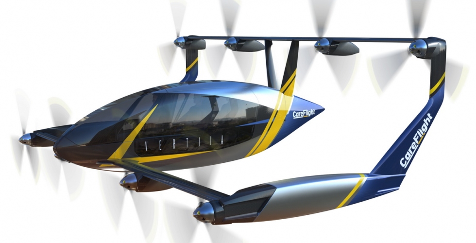 Australian company AMSL Aero has unveiled what it claims to be the world’s first electric air ambulances, launching the first prototype aircraft in Sydney on Wednesday as part of a partnership with air-rescue organisation CareFlight. The Vertiia prototype has been designed to take-off vertically, like a helicopter, but once airborne, flies with the aid of fixed wings, in the same way as a plane does. AMSL Aero says that this combination provides the aircraft with significant flexibility in where it can land, while also providing greater speed and energy efficiency. The company says that the aircraft would reach a cruising speed of up to 300 km/h and a range of up to 250km as an all-electric model with batteries, and a hydrogen fuelled version achieving a range of up to 800km. The aircraft was launched by deputy prime minister and transport minister Michael McCormack, who welcomed the prospect of an all-electric aircraft that had the ability to access difficult areas. “I remember growing up and watching the Jetsons and marveling at that futuristic technology. It’s right here, right now and it’s happening,” McCormack said. “What an exciting day to think that we’ve got a what will be a carbon neutral plane taking off, landing, in sites where there’s a mass casualty or indeed a hospital where somebody’s young, or somebody not so young, needs urgent medical retrieval and in sometimes even country areas, you can’t get to places easily” AMSL Aero CEO Andrew Moore says the vertical take-off and landing (VTOL) allows the aircraft to access areas without the need of a runway, and it had entered into a partnership with CareFlight for the development of an “electric aero ambulance”, that could provide crucial medical support to regional communities. Deputy prime minister Michael McCormack, with AMSL Aero co-founders Andrew Moore and Siobhan Lyndon. “Vertiia will instantly enable greater access to medical services for vulnerable remote, rural, and regional communities, offering new models of care through rapid and low-cost connectivity,” Moore said. “Unlike aeromedical planes that require a runway, Vertiia will carry patients directly from any location straight to the hospital, significantly reducing the complexity and time transporting vulnerable patients. “It will also be quieter and safer than helicopters, and will eventually cost as little as a car to maintain and run, transforming aeromedical transport into a far more affordable, accessible, safer, and reliable option.” CareFlight’s medical director Dr Toby Fogg said that the organisation had been attracted to the Vertiia aircraft, as its efficiency and lower operational costs, while providing the same flexibility as a helicopter, meant that it could potentially deploy more aircraft for the same cost, reaching more people needing assistance. “Initial scoping and modelling suggest that with Vertiia we would be able to reach more Australians. For example, the price point of operating Vertiia versus helicopters and fixed wing aircraft would mean we can purchase a much larger fleet aircraft, by several multiples. The lower operational costs would allow us to hire more doctors, nurses and paramedics,” Fogg said. AMSL Zero was founded in Australia in 2017 by co-founders Andrew Moore and Siobhan Lyndon with the initial versions of the aircraft having the ability to carry a pilot, a medic as well as transporting a patient. The partnership between AMSL Aero and CareFlight is being supported as part of a $3 million Cooperative Research Centres Project grant, and would include the University of Sydney and autonomy and sensing specialists, Mission Systems as part of the collaboration. CareFlight pilots will be involved in the design of the Vertiia aircraft, ensuring it meets the needs of medical services and could see electric air ambulances deployed within the next few years. The company already has its eyes set on the creation of a commercial version of the aircraft having the capacity to transport up to four people. Both the all-electric and hydrogen fuelled versions of the aircraft have the potential to operate with zero associated greenhouse gas emissions. A prototype of the Vertiia aircraft was unveiled at AMSL’s aerodrome located at Bankstown Airport in Sydney, where the aircraft has been undergoing construction. The aircraft is expected to undertake test flights from a facility at Narromine Airport, just outside of Dubbo. The Vertiia aircraft is being touted as one of the world’s most energy efficient aircraft and has the potential to be deployed in a range of applications, including commercial transport and flying taxis.
 -
If a person came up to you and said he wanted to learn to fly, what "positive" advice would you give them?
-
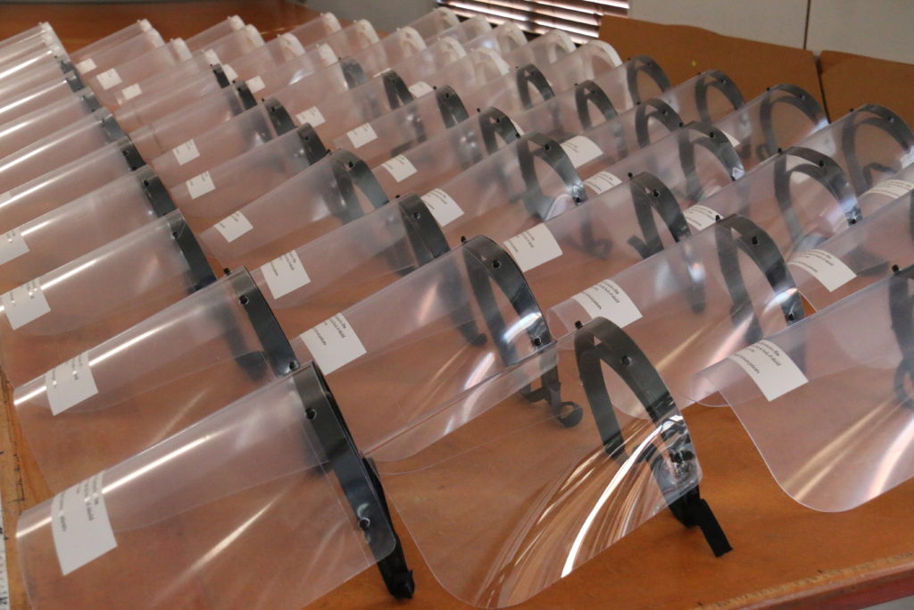 Bundaberg’s Jabiru Aircraft has created face shields with the help of 3D printing to provide extra protection for frontline workers dealing with Covid-19 cases. Bundaberg’s Jabiru Aircraft Pty Ltd, whose business usually focuses on producing light sport aircraft and engines, has responded to the current pandemic crisis by creating face shields utilising 3D printing technology to provide extra protection to frontline health workers dealing with Covid-19 cases. With these efforts Jabiru Aircraft joins other manufacturing entities and individuals around the world in producing emergency Personal Protective Equipment (PPE) during a time of global shortage. Jabiru Aircraft Business Manager Sue Woods said last Friday she and an employee, engineer Alex Swan, were looking at ways to support health care workers during the current public health situation, and with a little ingenuity and the help of a 3D printer they were able to design and commence the manufacture of the PPE. Sue said they were very concerned for the wellbeing of paramedics, GPs and medical personnel who were most at risk of contracting the virus. They hoped the extra layer of protection offered by the face shield would keep these essential people healthy. Both Sue and Alex have family members who work in healthcare, and they were on the same path of thinking – wanting to ensure not only their loved ones stayed safe, but also others facing the Coronavirus firsthand. 3D printers used to create face shields “I came to work one day after watching footage on the shortage of PPE and thought ‘what can we do'?” Sue said. “Alex experimented with cutting the visor section until we had the right shape and he modified the headband 3D file to accommodate glasses underneath. “We then had both a local dentist and a local doctor try the face shields, and check with sterilising products, and we had good response.” Jabiru Aircraft Pty Ltd has designed and manufactured emergency Personal Protective Equipment (PPE) during a time of global shortage in result of the Covid-19 situation. Two 3D printers are used by Jabiru Aircraft to create the head band for the face shield and the transparent polycarbonate for the visor is cut to shape with a flatbed CNC router. “Our engineer Alex Swan has been very motivated with this project and volunteered much of his own time, getting up in the middle of the night to keep the 3D printers going 24/7,” Sue said. “We have two 3D printers and Alex took them home so he could get up at 2am to press the button to start the next headband.” Sue said it took less than a week to develop the idea and start production of the face shields, and they hope to have 100 finished and shipped to paramedics in Western Australia by Monday. She said the slowest part of the production was the 3D printing and she was thankful for the support from other local organisations who offered assistance. “To increase our production rate of the 3D printed component, CQUniversity Bundaberg and Gladstone and Makerspace Bundaberg and Hervey Bay, along with CQUniversity Makerspace have jumped on board very quickly, and we now have several additional 3D printers in action,” she said. “We are also getting offers of assistance from schools in the local community.”
 -
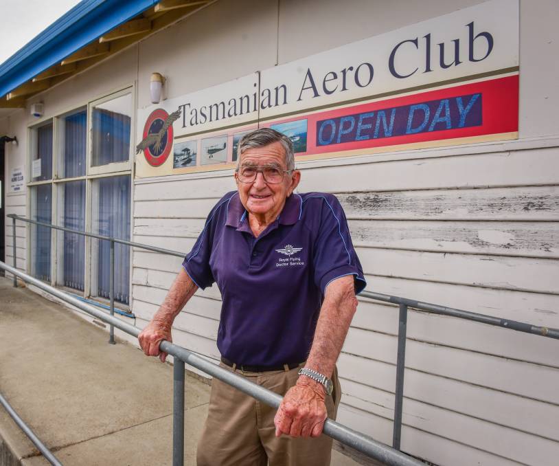 Time has flown by with November 23 marking the 90th anniversary of the first flight from what was the Western Junction Aerodrome and is now the Launceston Airport. The first flight in 1930 was undertaken by pilot Joe Francis in the Gipsy Moth VH-ULM, leased by the Defense Department to the Tasmanian Aero Club. Club historian Lindsay Millar said the first flight was crucial to aviation in the state. "That first flight really marked the beginning of permanent commercial aviation in Tasmania." "From that very beginning, that first flight here at this airport on November 23, 1930, that was the catalyst for everything." The flight led to the formation of Tasmania's first air service, Flinders Island Airways, which eventually, after many different changes and amalgamations, became Australian National Airways, one of the world's largest airlines. Mr Millar said the anniversary crept up on them. "It is amazing and I have been privileged to belong to the Aero Club since 1956. I have been able to share the history of that club in that period," he said. The plane that made the historical first flight is also, once again, touring the skies. The restoration of the plane was started back in 2002 and was completed in 2012 with the original Aero Club colours. The VH-ULM after its restoration was finished in 2012. "The incredible thing about the flight VH-ULM is that the aircraft still exists and is now flying in Queensland," Mr Millar said. "That aircraft after being in private hands for some years and then in a a museum, it's back in the air again, better than brand new." The Tasmanian Aviation Historical Society president Andrew Johnson said it was remarkable the plane was still running. "This aircraft has been restored and looked after and still flying. That makes the whole story really special." Lindsay Millar with model of first flight plane. Mr Johnson said the first flight was the start of quite a significant aviation story in Tasmania. "That first flight led to numerous other flights and to individuals who were pioneers in aviation taking up the concept of flight and developing it from, I suppose a bit of a novelty idea, to commercial flying." "It did pave the way for others." On November 23, the Tasmanian Aero Club rooms will host a special function to recognise the anniversary of the flight and celebrate how far aviation has come because of that moment. "We believe it's an important story and that's why the [TAHS] was formed - to shine some light on it and I think that's the start of it," Mr Johnson said. "From now on we will start to really recognise the events and the significant dates of aviation in Tasmania."
 -
 Packing for travelling light Always a problem – so many compromises have to be made. The old adage, "If in doubt, leave it out ...", needs to be applied often, but there's still lots of pondering, hefting, agonizing, and re-packing. I've gone through the process dozens of times over the years, preparing for long backpacking and motorbike trips, and now ultralights. It does get easier, especially with the lightweight gear now on the market, and I have learned a few tricks that I'll pass on to anyone interested. As you'll see, I like my comforts as well, and have found ways to bring them with me, folding chair included! First of all, I would never leave my self-inflating mattress behind. It's 3/4 length, 25 mm thick when inflated, rolls up to a small bundle deflated, and weighs very little. You'd think that thickness (thinness) wouldn't be of much use, but it does wonders for a comfortable sleep! If the cost seems too much (about $90 when I got mine), then at least get one of those blue foam mats. Even 8 mm thickness of that blue foam is enough to make a really big difference on cold, hard ground, and cut down to 3/4 length also weighs very little. To carry the mattress on the aircraft, I use a couple of short pieces of light bungee cord (3–4 mm diameter) tied in loops like strong rubber bands to keep the mattress rolled-up, then another couple of loops of the bungee tied around a convenient tube on the aircraft, and just slip the rolled mattress under these loops — nothing to tie/untie every time, and very secure. Inside the wing would be a good place, if you have access on your aircraft. A sleeping bag is the next obvious necessity for camping out. There are lots of options here, but I find that combining a light-weight sleeping bag with lots of cold weather flying clothing gives the most flexible combinations for all-weather flying and camping at minimum weight. So let's first have a look at flying clothing. Flying warm Having been raised on the central plains of Canada, then spending months at a time living on motorcycles in all weathers has taught me a bit about dressing to survive the cold. I did a lot of suffering in those early days before I learned better. Let's start at the inside, where you can make the biggest gains in warmth. I really don't understand why long underwear gets the jokes and ridicule that it does. It's by far the most effective warm clothing of all, for it's weight. The polypropylene thermal underwear available these days is soft, form-fitting and stretchy, and easily fits under other clothing. It wicks moisture away from the skin and provides a layer of warm air next to the skin, just like I would imagine the layer of fur does for a cat! When not being worn it packs into a soft bundle and weighs very little. The jeans and shirt going over it provide very little warmth for all their weight; far warmer and more comfortable is to travel in a track suit. Over the shirt go a couple of lamb's wool sweaters. These are the soft, fluffy, 'lounging' sweaters, either V-neck, or crew neck to your preference. Two (or more) layers like this is much, much, warmer and lighter than one heavy jumper, and more flexible and comfortable. When not needed they stuff easily into your travelling bag. When your flying jacket goes over all this fluffy bulk you'll feel like a fat teddy bear, but at least you'll be a warm and cosy bear! The sweaters are for sale in 'recycled clothing stores for a couple of dollars each, so not a cost problem, but get a larger size for comfort. (I actually bought a couple of them in Narromine one time, when ferrying an open ultralight from Geelong, and a freezing cold front caught me unprepared; nice and warm all the way after that.) If you wear a flying suit then your legs are already covered, but if you wear a flying jacket, then you need some outer pants – it's no use being a cosy bear on the top while losing all your body heat from your legs. Those insulatedski pants are ideal. They're wind-proof, warm, light-weight, and come well up under the jacket for a good seal. But this isn't all that you can do; don't forget those cold feet. I carry several pairs of light wool socks, and wear two or three pairs at once on a long, cold flight, with another couple of dry pairs to change into at fuel stops. Another important bit of clothing is a scarf, to seal around the collar of your jacket, and protect the back of your neck. I just use a T-shirt for the purpose, since it can double as a spare shirt as well. Even more effective is a balaclava, which will seal in the whole head and neck. For the hands, ski gloves with the tips of the fingers cut off, work well for me – warm and still have good dexterity. Dress like this and you won't be cold, regardless of the conditions. I know that all this seems like a lot of stuff, but the extra, besides what you would wear anyhow, doesn't weigh much at all, and much of it will double for your sleeping gear as well. Of course, the other advantage of all these layers is that you can arrange them to suit the conditions at the time, whereas if you depend only on a very warm flight suit, it can be stifling on a hot day, and yet too bulky and difficult to pack away. Sleeping Sleeping warm So I just carry a lightweight summer sleeping bag all year. But a roomy one, because inside it I wear as much of the flying clothing as is necessary for the temperature of the night. I don't know where the myth comes from about it being warmer in a sleeping bag with your day clothes off — I find just the opposite, and I've had many teeth-chattering nights to put it to the test. There are several advantages to wearing lots of clothing inside a sleeping bag; not the least of which is, if you need to get up in the middle of the night for whatever reason, it's no sense exposing any more skin than necessary to that chill night air! As a minimum I use my thermal underwear as pyjamas, and if the night is cold enough, then my track suit pants and a jumper as well. The track suit pants are the ones with two layers of light fabric rather than the thick fleecy ones — lighter and easier to pack away. Then when I get up in the morning to stir up the fire, I'm already dressed enough to be comfortable, without having to get into cold clothes. If it's a really freezing cold night then I'll wear everything (except jeans, they're just too uncomfortable), including flying jacket and ski pants, not forgetting a couple of pairs of dry wool socks and the T-shirt wrapped around my head. With all these options I can be comfortable anywhere from the tropics to the frosty high plains. The sleeping bag should have a hood to keep your head warm, since 20% of body heat is lost there. And it must not have a fleece lining — the fleece feels nice on bare skin but it drags on your clothing when you roll over, and collects every bindi [burr] in the west if it gets a chance. Sleeping really light The next essential for lightweight camping is a 'space blanket' (that may be a trademark name, but I'll use it anyhow). It's also an essential part of any survival kit so I have a space blanket permanently in my aircraft, even for local flights; once again it weighs little and is held in by a couple of loops of light bungee cord around a convenient tube. When camping really light, I use the space blanket as a ground sheet, pulled partly over the sleeping bag on the side which any draught is coming from. Stopping that draught from getting at your back makes a really big difference to staying warm at night. Putting another space blanket right over the sleeping bag sure is nice and warm, but condensation will wet parts of the sleeping bag — but if it's raining it's still a lot better than cold rain soaking the bag. If the second space blanket is set up like a lean-to, with a fire in front, it's like a reflector oven and is the warmest camp of all! Avoid the cheap imitation space blankets on the market, made of that blue tarpaulin material aluminized on one side — they're much heavier and stiffer than the original brand 'Space Blanket', and not nearly as useful. One last essential for sleeping out is a mosquito net! It only takes one persistent mossie at 3 a.m. to ruin a good sleep (and if there's one buzzing around you, others will hear the buzz and come over to get their share). The lightest solution that I've found is to carry one of those fly nets that fits over a hat. So I sleep under my hat and try to tuck the net into the bag — it's awkward and prone to coming loose if I roll around to much, but sure is better than trying to breathe inside the sleeping bag on a tropical night! Five star accommodation Of course the way to really beat the mossies, and get a whole lot of other comforts as well, is to have a tent. And that's possible these days with the light-weight tents on the market. Mine weighs just 2 kg, and is a great little 'cocoon'. It not only keeps the mossies well away, but it stops that chilling draught, keeps the dew off, and provides shelter to keep my gear and boots dry if there's rain in the night. I used to 'sleep rough' with only a ground sheet and sleeping bag, but now I'm hooked on the comforts of my little tent. So what doall those 'very littles'add up to? The flying clothing — ski pants, track suit pants, 2 sweaters, T-shirt, gloves, 5 pairs socks, and thermal underwear — weigh 3 kg. (The flying jacket is so much a part of me that I consider it as part of my personal weight.) The sleeping bag, mattress, and 2 space blankets add another 3 kg, and the optional tent is 2 kg. Stuff it all into a light-weight sports bag (along with a small pillow for real comfort) and that's9 kg — not too bad for a kit that's sufficient for flying and sleeping-out in just about any weather, and in reasonable comfort. Basic survival gear Every aircraft should always carry some basic survival gear, even on short local flights. That may seem a bit extreme to most casual fliers, but let's have a think about it, and maybe you'll decide to carry at least the basics in future. Hopefully it'll never be needed for a critical 'survival' situation, but much more likely just an unplanned night spent out somewhere, due to bad weather or mechanical failure. Water In this hot, dry Australian land it's really amazing to see fliers ignoring all lessons of common sense by flying off without any water at all on board! Even without the possibility of being stranded by an emergency landing, it's really nice to have some good drinking water at hand. I always have at least two litres of water in my aircraft — one litre bottle right handy for a refreshing drink whenever it suits, and another litre bottle secured in the pod. That's enough, if used sparingly, to make a really big difference if I get stranded somewhere overnight. Two litres is the absolute minimum, but if you're going away from the settled coast and the weather is really hot then of course much more is required. To carry more water the best containers these days are those tough nylon water 'bags' sold by good camping stores — much easier to pack into corners of the pod, or wherever, and easier to tie down than hard containers. They're also handy for trimming the balance of an aircraft (seems ridiculous to see some aircraft with a lump of lead permanently in the tail, when a few litres of water would have the same effect, and be a handy reserve as well!) Space Blanket This is the most useful survival equipment you can carry; it could save your life in either hot or cold conditions. I have one permanently secured in my aircraft. It weighs less than very little and is easy to roll up and tie to some tubing somewhere out of the way. One of the most likely causes of being forced down is due to bad weather, and that might well mean being caught out in cold rain for a couple of days or more. No shortage of water, but without shelter it could easily get to hypothermia. In extreme cold, wet conditions it's best to crouch down, or sit in the aircraft seat, with your knees against your chest, trying to be as small as possible, with the space blanket over your head and around you like a shawl. This way you best contain your body heat and shed the cold rain. It gets pretty cramped and uncomfortable, but you can at least survive in some really cold conditions this way. If you have the means of lighting a fire and keeping it going, then the the space blanket rigged as a lean-to can turn a survival situation into real comfort. In the event of being stranded in hot weather, the space blanket once again is a saviour. If you have limited water, then it's very important to reduce the losses. Watch kangaroos for a good lesson on how to manage these conditions. During the heat of the day, especially in drought conditions, they select the best shade they can find and then just lie there without moving at all — same should go with us. Chasing around looking for bush tucker or digging for water is usually a complete waste of precious energy. Tie the space blanket over some low bushes, crawl underneath with the water you have, and lie absolutely still. Try to 'slow down' and get into a state of slumber, breathing as slowly as possible through the nostrils, and stay that way; you can survive much, much longer in this state of suspended animation than if you were up and moving around. Let's hope it never comes to this extreme for any of us, and it shouldn't if you carry an ELT, but it's good to know, just in case ... Fire lighters I always keep at least two of those gas cigarette lighters on hand, one inside the rolled up space blanket, with another one always in the shoulder pocket of my flying jacket. Some purists insist on matches, but my experience indicates that the lighters are much better than even the best 'waterproof' matches — with those lighters that have an adjustable flame it's like lighting a fire with a blow-torch! In Australia it's nearly always possible to find enough suitable wood to light a fire, and that fire can be really essential for survival. With the space blanket rigged as a lean-to in front of a good fire, you can be dry and cosy. Light the fire against a log, with a couple of heavy bits stacked across on top, and it reflects the heat into the lean-to as well as protecting the fire from the rain. VERY IMPORTANT! A campfire isn't all that visible from the air unless it has a good plume of smoke in daylight or a flare-up at night. So if you're depending upon an aerial search (due to your ELT signal of course), then keeping a good fire going is essential. Have a bundle of foliage ready to throw on to make lots of smoke in the daytime, or a big bundle of light branches on hand to make the fire flare up quickly at night, in case you should hear an aircraft approaching. Mirror Another way to assist a search aircraft, or even possibly attract the attention of any passing aircraft, is with a signalling mirror. A bright, persistent flash from the ground really catches the attention, and that's easy to do if you have a mirror on a sunny day, and know how to use it. The plastic ones from camping supply are light and easy to carry, so is a CD; mine lives in the map pocket, but inside the space blanket would be good. It should have a hole in the middle; if not then drill an 8mm hole. To use it, hold the mirror against your eye with the reflective side away, peeping through the hole at the aircraft. Reach out with the other hand as far as you can, holding a finger tip in line with the target, and adjusting the angle of the mirror to shine the reflection onto the finger tip. Practice it with a friend at your airfield and you'll see how brilliant and distinctive the flash is, even at a great distance. ELT Well of course every aircraft should carry an Emergency Locator Transmitter. The little pocket ones are excellent, and affordable — no logical reason not to carry one these days. They're really effective, as I've proven a couple of times — both times I could have been rescued really quickly if the emergency was real. Those false alarms were just embarrassing, but it's very consoling to know that the system works so well. But the ELT must 'live' in the aircraft at all times, even for short local flights. Work out some form of mounting so that the ELT is permanently near at hand, but can be quickly removed if a speedy exit is needed. Food Food is certainly the most over-rated item in most survival manuals. All that talk of chasing around looking for little bits of 'bush tucker' and trapping animals is nonsense — far better to just lay still and conserve the reserves of energy your body already has in store. We can all go for a couple of days without any food at all, and some could even benefit from the enforced diet! Some care also needs to be taken in selecting food to carry along. For example, the often recommended 'beef jerky' would be absolutely the worst selection I could think of — not only is it a desiccated product that needs water to reconstitute, and salty that needs water to balance, but all such meat protein foods need even more water for the digestion process. It's not as if we need body-building protein in that situation — we need energy, easily digested energy. So I carry tubes of Nestle's sweetened condensed milk! Yes, it's by far the best 'survival' food that I can find. It has heaps of sugar for that instant energy, and milk for sustained energy, and the little bit of fat and protein that makes the stomach feel like it's had at least a bit of a feed. If you also have a little billycan hidden away in the aircraft, then Nestle's milk in hot water makes a very warming and sustaining drink on a cold, wet night. In a pinch you can just suck it out of the tube, along with comforting memories of childhood. So, inside my rolled up space blanket I also carry a tube of Nestle's, just in case ... I usually have several muesli bars stashed away in a pocket under the seat of my aircraft. They're for snack food and 'flying breakfasts', but would make good survival food — if enough water was at hand. Repellant Last, but not least, I reckon insect repellant is an essential to good survival. Not only do mossies drink your precious blood, but a night spent fighting them means the next day being so tired that you can't even think straight — and sufficient rest for clear thinking really is an essential for survival. Many survival crises have been made much worse by muddled thinking and panic, often brought on by exhaustion, so this is important. Just the smallest bottle available, or those individually packaged 'wipes', is all that's needed. Clothing Shouldn't even have to mention this, but a hat can make a real big difference for comfort, and even the chances of survival in either cold rain or hot sun. If you don't wear a hat regularly, then at least include one in the survival kit. My insulated flying jacket comes with me in the aircraft all the time, winter and summer. My ski pants are stashed out the way in the wing all the time. With the jacket and ski pants and the space blanket, and a good fire, I can be pretty comfortable on even a very cold night. So the minimum 'survival kit' that I reckon should be in any aircraft, all the time, (space blanket, lighters, mirror, repellant, ELT ) weighs less than a kilo, plus two kilos of water. So that's 3 kg for enough gear to survive for a day and a night without too much distress – sure sounds a lot better to me than being out there with nothing! STRICT COPYRIGHT JOHN BRANDON AND RECREATIONAL FLYING (.com)