IBob
-
Posts
3,075 -
Joined
-
Last visited
-
Days Won
26
Content Type
Profiles
Forums
Gallery
Downloads
Blogs
Events
Store
Aircraft
Resources
Tutorials
Articles
Classifieds
Movies
Books
Community Map
Quizzes
Videos Directory
Everything posted by IBob
-
 Weird that folk can accept a vehicle travelling crosswind and on various headings at well over the windspeed, but they can't consider a mechanism for doing that in one particular direction......)
 -
Maybe part of the confusion is around what is driving what. As I see it, the wind is pushing the car (downwind). If the car is moving, the wheels are turning. If the wheels are turning, this causes the prop to turn, since the two are linked. And the prop is pitched to blow backwards , into the wind. It's the wheels that are driving the prop, not the other way round. And if the car is travelling downwind at wind speed, the prop is turning, pushing back against that wind, so causing the car to go faster than wind speed.
-
BTW and if anyone is interested, the performance of evac tube solar water heating is outrageous: I have the smallest 20 tube system and it provides all our hot water for about 9months of the year, and some of it for the other 3 months. The operating principals are totally different to the old flat plate technology. This thing is actually a heat pump that works even on overcast days. Heading into summer, I am (again) looking at ways to dump the excess heat. Ours is a low pressure system. My only reservation in a high pressure system would be the long term durability of the header that takes the tubes.
-
Yep, I have an evac tube solar hot water system, with the collector some distance from the hot water tank. Took a fair bit of tinkering to get it settled down. The supplier kept insisting the (multispeed) circulation pump be turned up due to the distance, in the end I turned it down to minimise cavitation as the water temp rises. It still grumbles sometimes, but it works, and has been for some years now.
-
Turboplanner, I live in a 1920s bungalow, with a header tank lifted as high as it will go in the roof space (not very high, about 1.5m at the base, due to shallow roof). The outfeed goes horizontal across the width of the ceiling space, then down a cavity to under the floor, where it is then split out and piped to the various taps and hot water cylinder. The header tank is supplied by a pump. If we allow this system to drain during a power cut, it will not then prime itself once we have water back in the header tank: nothing will come out of any of the taps, including the lowest, which are bath taps approx 700mm off the floor. To get the system going again, I go out to a tap I installed which is almost on the ground and connected to the lowest part of the system. Turning this on results in about a minute of gurgling and spitting, then a small amount of water, then full stream. On the odd occasions when house-sitters have been told what that tap is for, they listen to this with an expression of benign disbelief. And even though I figured out why this happens, it's still oddly counter intuitive to have a tank in a roof and taps down below, but no water coming out... I found this situation instructive when it came to building my aircraft: I went to some lengths to remove any undulations in the fuel pipework.
-
It's certainly a curly one, Bruce, and if we can believe the story, the physics prof lost $10,000 and I would suggest part of his reputation because he couldn't see it. While some of the principals are different, I found the wheely thing at about 1330 on the YouTube recording quite useful: it shows a free running wheeled object being driven forward by something pushing on it, but travelling forward faster than what is pushing it. In a sense that is what the wind car is doing: being pushed by the wind, which turns the wheels, a certain amount of that turning energy then being used to push back against the wind.
-
Bruce, if the wind dropped to zero, the various frictions of the wheels etc would cause the vehicle to slow and stop. Exactly as it does with any other vehicle. I can see where this may look like and attempt at a perpetual motion machine, but it's not. It would only be that if the thrust developed by the prop was greater than the rolling energy required to drive the prop. So it can't work in nil wind, but with a constant wind delivering energy to the system (by pushing it along), very careful gearing and avoidance of friction enable the rolling wheels to also turn the prop. I would suggest there is a narrow envelope where this works, or we would indeed have something that accelerates indefinitely!
-
Bruce. with no wind the only force acting on the thing would be gravity (okay, and equal air pressure all round) and no resulting movement on flat ground.
-
We just had yet another Americas Cup, with all the contenders sailing faster than the speed of the wind. Granted this was not downwind, and granted the mechanics of what is going on is different and initially counterintuitive, but I can see no reason to reject it out of hand just because we can't initially see how it works.
-
I don't see why not: in both cases the air is moving relative to the surface. If you think about it, the planet we live on is one enormous treadmill moving under the atmosphere around it?
-
I'm amazed at how very polite and civilised this conversation is. And especially in light of the fact that a slice of the aviation fraternity still measure their masculinity by the position of their third wheel...............)
-
Looking really good there! Just PM'd you.....
-
Marty_d who is building a 701 but using some savannah parts including wiring, raised the same question here on 11 August: https://www.recreationalflying.com/topic/28196-marty-ds-ch-701-build-log/?do=findComment&comment=512650&_rid=6547 It's not clear what the other wires are intended for. But it would be nice to know!
-
The fuse sits between: terminal B on the voltage regulator and the starter relay, where it is attached to the same terminal as the heavy + cable coming from the battery: that is item 4 on page 3/9. So, one side should have a spade terminal to go onto the voltage regulator, the other side a lug to go onto the starter terminal bolt. That much is clear. I don't know about any third wire.
-
Marty, I would be surprised if there is a build yet that didn't also involve the removal of rivets: in my case I riveted one whole area 3 times over, before slamming the shed door and taking a long break! The Savannah now has hatches in the pans under the seats, but it's still fiddly trying to work through them, as I recently discovered when shifting my headset sockets.
-
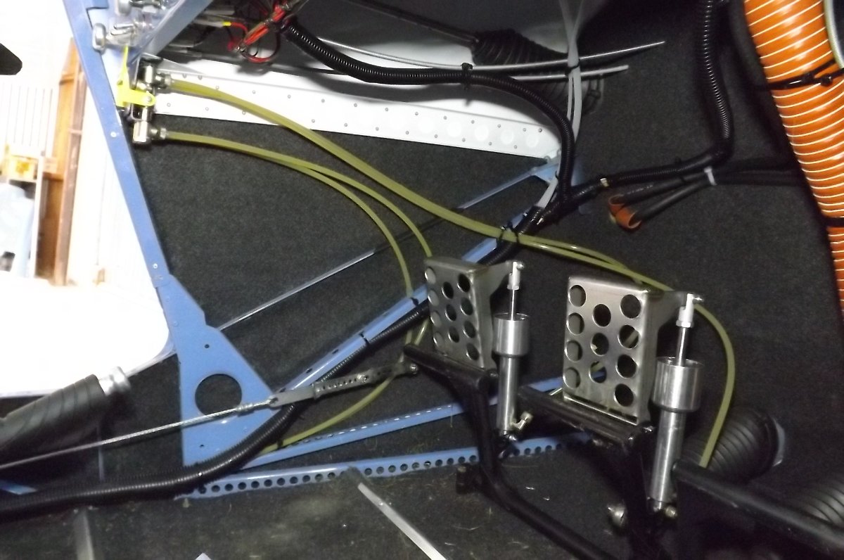
Hi Steve. Yes, I ran both brake lines back along the LH fuselage and in under the seats. In the cockpit, I tucked them away in the split corrugated black plastic sleeving you see there, which does a nice job of tidying the various tubing and wiring. The RH brake tube then crosses over through the bottom of the tunnel. I'm not saying this is how it 'should' be done, it's how it worked best for me. I made sure all piping and wiring is anchored at various points to prevent any vibration and chafing. It's a really good idea to leave the seat pans out until this piping and the wiring is all done, especially the LH seat pan but ideally both of them. It makes the job a whole lot easier.
- 12 replies
-
- 1
-

-
- savannah
- savannah s
- (and 1 more)
-
Hi Bodie, here is a pilot only brake setup. It also has park brake at the top left of the pic: if you haven't got that the lines would loop forward then run back along one of the stringers there. You will use a fair bit of rudder on the Savannah, so the lines need to be looped forward to stay clear of the pedals etc before running back down the side. Since the brake lines are quite stiff and the couplings at the cylinders point forward, they tend to loop forward anyway. I can't speak for the dual brake setup, but the same would apply: the lines need to be looped forward. Once you have the nosewheel and rudder on and hooked up, it is then quite easy to check where the lines sit as you operate the pedals.

-
Hi Bruce. So far as I know, Savannahs with the standard 2 wing tanks normally have no valves from the wing tanks. These feed down into a 6L header tank behind the passenger seat. The header tank is fitted with a float switch at the top, which brings on a low fuel indicator at the dash: provided this is working (more on that later) it gives approx 20mins of low fuel indication. This arrangement does occasionally get a small amount of air in the header tank, giving false low fuel warnings. More recent builds now have a breather from the header tank back up to a high point in a wing tank to deal with this. Aside from that, it works very well. .................................................................................................................................................................................. The only shortcoming I see with this system is that there is no way to test the header float switch without fully draining the wing tanks. (There is a test button on the panel, but this only tests the indicator, not the switch.) I have a 4 tank setup with individual tank valves and a header breather: I can readily test the low fuel indication by valving off all tanks. I do need to know it is working if I intend flying my outer tanks to exhaustion. ................................................................................................................................................................................... As an aside, I also think some care needs to be taken with the wing tank breathers. In a perfect world, these tanks would be cross vented, and so sharing the same vent pressure. If the vent pressure imbalance is large enough, you will definitely get fuel crossfeeding from one tank to the other. I think this is best avoided by keeping vent pressures positive but low. The Savannah standard has individual underwing vents cut of at approx 45 degrees into the airstream and that seems to work okay. The other popular option seems to be 'snorkel' pipes up out of the fule caps then bent down and forward.
-
That's a neat arrangement, Blueadventures. Thanks for posting: I must see if I know anyone with a printer.
-
Thanks Blueadventures, I'd like to see what you've done with the controllers: it's been one of those annoying details for me!
-
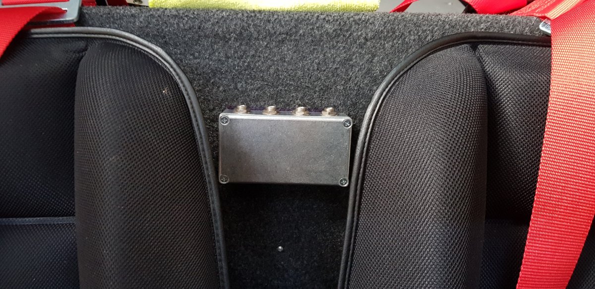
Hi Mark, I've been wondering the same thing about the headset jacks. I have the Lightspeed headsets, which have the inline battery holder/controls pod about 400mm from the plugs, and I've yet to come up with an arrangement that works well with that. Initially I had the sockets in the floor console, and the pod would end up between the seats, which was okay but a bit messy with a passenger. I recently moved them to a box between the seat backs, had hoped the cable and pod would sits over my right shoulder, but it slips off all the time. I'm now thinking along the lines of velcro or some such to anchor the pod: it's not something I need to access much once I get going, but I don't like it hanging loose. Another popular spot for the sockets is down into the front corners of the baggage shelf, next to where the fuel lines etc go down. I believe this is where the factory fits them. I didn't put them there as I didn't want the cable between me and the door, but that's maybe not such an issue. I'd still have to anchor the pod somehow...... Do let me know if you come up with anything better?
-
Facthunter I don't think he's talking about T into the wing tank vent line: he's looking at T ing the vent from his header (receiver) tank into the fuel return line that goes into the top of the RH tank.
-
1. In my view, T- ing in as you suggest will likely work very well for the header vent, and I can see no possible drawbacks. 2. The Sav uses 1/4" for the vent. I can't remember for the Fuel return and pressure gauge. It has to be small enough to match the fitting on the gauge. The flow is minimal so as small as you like there, but 1/4" is fine if it fits.
-
Yes kgwilson, I don't know what I was thinking when I said the harrier is the only NZ raptor. Pretty rare to see a falcon in the parts I have lived, though we did have a young one visited our garden in Havelock North one winter. Initially we crept around to get a better look without scaring it off: it then became evident that it wasn't in the least bit worried about us, sat low in a tree just looking at us, then finally left when it felt like it. You're a lucky man to have flown with one! Somebody who knew somebody I knew did a degree study on them: it seems they come in 2 varieties, bush and open country, with quite different flight characteristics, as you might expect.
-
I think part of the appeal of this guy was that he was doing this stuff with a nosewheel and not overly large tires on a 182. The 182 came to grief, but that was principally due to engine failure, which seems to have been due to foreign matter blocking an oil passage.