IBob
-
Posts
3,085 -
Joined
-
Last visited
-
Days Won
26
Content Type
Profiles
Forums
Gallery
Downloads
Blogs
Events
Store
Aircraft
Resources
Tutorials
Articles
Classifieds
Movies
Books
Community Map
Quizzes
Videos Directory
Everything posted by IBob
-
Hi Steve. Yes, I ran both brake lines back along the LH fuselage and in under the seats. In the cockpit, I tucked them away in the split corrugated black plastic sleeving you see there, which does a nice job of tidying the various tubing and wiring. The RH brake tube then crosses over through the bottom of the tunnel. I'm not saying this is how it 'should' be done, it's how it worked best for me. I made sure all piping and wiring is anchored at various points to prevent any vibration and chafing. It's a really good idea to leave the seat pans out until this piping and the wiring is all done, especially the LH seat pan but ideally both of them. It makes the job a whole lot easier.
- 12 replies
-
- 1
-

-
- savannah
- savannah s
- (and 1 more)
-
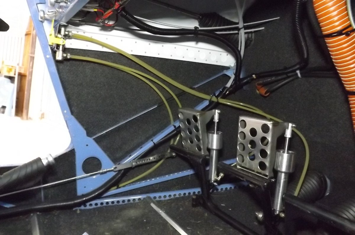
Hi Bodie, here is a pilot only brake setup. It also has park brake at the top left of the pic: if you haven't got that the lines would loop forward then run back along one of the stringers there. You will use a fair bit of rudder on the Savannah, so the lines need to be looped forward to stay clear of the pedals etc before running back down the side. Since the brake lines are quite stiff and the couplings at the cylinders point forward, they tend to loop forward anyway. I can't speak for the dual brake setup, but the same would apply: the lines need to be looped forward. Once you have the nosewheel and rudder on and hooked up, it is then quite easy to check where the lines sit as you operate the pedals.

-
Hi Bruce. So far as I know, Savannahs with the standard 2 wing tanks normally have no valves from the wing tanks. These feed down into a 6L header tank behind the passenger seat. The header tank is fitted with a float switch at the top, which brings on a low fuel indicator at the dash: provided this is working (more on that later) it gives approx 20mins of low fuel indication. This arrangement does occasionally get a small amount of air in the header tank, giving false low fuel warnings. More recent builds now have a breather from the header tank back up to a high point in a wing tank to deal with this. Aside from that, it works very well. .................................................................................................................................................................................. The only shortcoming I see with this system is that there is no way to test the header float switch without fully draining the wing tanks. (There is a test button on the panel, but this only tests the indicator, not the switch.) I have a 4 tank setup with individual tank valves and a header breather: I can readily test the low fuel indication by valving off all tanks. I do need to know it is working if I intend flying my outer tanks to exhaustion. ................................................................................................................................................................................... As an aside, I also think some care needs to be taken with the wing tank breathers. In a perfect world, these tanks would be cross vented, and so sharing the same vent pressure. If the vent pressure imbalance is large enough, you will definitely get fuel crossfeeding from one tank to the other. I think this is best avoided by keeping vent pressures positive but low. The Savannah standard has individual underwing vents cut of at approx 45 degrees into the airstream and that seems to work okay. The other popular option seems to be 'snorkel' pipes up out of the fule caps then bent down and forward.
-
That's a neat arrangement, Blueadventures. Thanks for posting: I must see if I know anyone with a printer.
-
Thanks Blueadventures, I'd like to see what you've done with the controllers: it's been one of those annoying details for me!
-
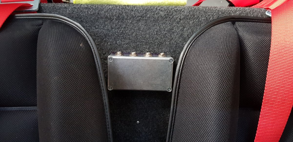
Hi Mark, I've been wondering the same thing about the headset jacks. I have the Lightspeed headsets, which have the inline battery holder/controls pod about 400mm from the plugs, and I've yet to come up with an arrangement that works well with that. Initially I had the sockets in the floor console, and the pod would end up between the seats, which was okay but a bit messy with a passenger. I recently moved them to a box between the seat backs, had hoped the cable and pod would sits over my right shoulder, but it slips off all the time. I'm now thinking along the lines of velcro or some such to anchor the pod: it's not something I need to access much once I get going, but I don't like it hanging loose. Another popular spot for the sockets is down into the front corners of the baggage shelf, next to where the fuel lines etc go down. I believe this is where the factory fits them. I didn't put them there as I didn't want the cable between me and the door, but that's maybe not such an issue. I'd still have to anchor the pod somehow...... Do let me know if you come up with anything better?
-
Facthunter I don't think he's talking about T into the wing tank vent line: he's looking at T ing the vent from his header (receiver) tank into the fuel return line that goes into the top of the RH tank.
-
1. In my view, T- ing in as you suggest will likely work very well for the header vent, and I can see no possible drawbacks. 2. The Sav uses 1/4" for the vent. I can't remember for the Fuel return and pressure gauge. It has to be small enough to match the fitting on the gauge. The flow is minimal so as small as you like there, but 1/4" is fine if it fits.
-
Yes kgwilson, I don't know what I was thinking when I said the harrier is the only NZ raptor. Pretty rare to see a falcon in the parts I have lived, though we did have a young one visited our garden in Havelock North one winter. Initially we crept around to get a better look without scaring it off: it then became evident that it wasn't in the least bit worried about us, sat low in a tree just looking at us, then finally left when it felt like it. You're a lucky man to have flown with one! Somebody who knew somebody I knew did a degree study on them: it seems they come in 2 varieties, bush and open country, with quite different flight characteristics, as you might expect.
-
I think part of the appeal of this guy was that he was doing this stuff with a nosewheel and not overly large tires on a 182. The 182 came to grief, but that was principally due to engine failure, which seems to have been due to foreign matter blocking an oil passage.
-
M........and RayBans. We had the aerobatics champs here a couple of times, and the airfield was a sea of RayBans........)
-
NomadPete, we have a very big native pigeon here in NZ, called a kereru. Like most pigeons, there's a lot of noise and flap when they first take off, but also like most pigeons, they go very well once they get going. During the summer season, they pull a manoeuvre much as you describe: from fast horizontal flight, a tight curved gliding pull up into the vertical , tipping back into a dive just on stall, then a curved gliding pull out. And in steep bush country, I've seen it combined with what topdressing pilots here used to call a split-arsed turn: the pigeon shot out of the bush on a steep hillside, tight curved pull up with a wingover just on stall, down, pull out and shot back into the bush where he came out. Either way, it's lovely to watch. And they're not bug eaters, so I'm pretty sure it's recreational. We also have harrier hawks here, they are our only true raptors: they normally soar along hillsides and fencelines at no more than 100-200' looking for lunch. But I've also seen them swooping and rolling up under cloud, and I'm sure they are playing in the turbulence.
-
Nope, it's for the jetjr.......
-
Okay, I'll ask the stupid question: What sort of sender? And if float, are you sure the senders aren't upside down???
-
Fortunately, the 701 has an admirably simple and reliable fuel system layout: high wing tanks feed into a receiver(or header) tank behind the pax seat. The receiver tank holds 20mins of fuel and has a switch at the top wired to a panel light, which comes on after about 2.5mins in cruise if no more fuel is arriving. On newer builds, the receiver tank also has a vent line running back up to a high point in one of the wing tanks. Provided the builder does a reasonable job of running the pipes from tank to wing root level or downhill, and without undulations, it takes care of itself without any need for pumps or valves. Crossporting the tank vents would put the icing on the cake...
-
Marty, it's pretty straightforward: You know the height difference between your tanks and the receiver tank behind the seat. You've got your fittings. Get the hose you're looking at using, and the fittings and set it up at those heights on the bench, with some sort of vessel at the top, and another at the bottom. Put in a known amount of fuel and time how long it takes to arrive. Online calculators are more normally used for longer runs of larger pipe at higher pressures, all sitting on the ground. They're good for sizing that sort of thing up. But in an aircraft, you're looking for the reasonable minimum (weight) that will do the job in practise. So, you're not looking for opinions, or for theoretical answers. You're looking for a practical answer as to whether your aircraft fuel system will deliver through 1/4" pipe fittings. And you check that by trying it.
-
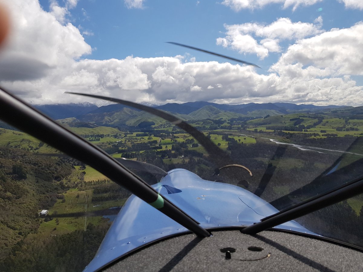
First fly since lockdown (it lifted a week ago but wx has been marginal and I've been helping with a build). After 5weeks, the engine would not initially fire at all: it took 3 sustained crankings of 7 or 8 sec with breaks in between plus cycling of the fuel pump. This was a first for this engine: in 180hrs of operation it has always started just about instantly. At a guess I would say very stale fule in the carb bowls? Once it did fire it vwas business as usual. So, a few circuits to make sure the feet still work, then a short flight over towards the ranges: this is one of many river valleys in the foothills. Broken cloud, base approx 2000', stayed under dodging light showers, carb heat on to avoid icing (the online time I've ever had this engine cough was flying up under cloud base.)
-

E-Props ...who has first hand experience with these
IBob replied to eightyknots's topic in Engines and Props
That red Sav must have been very naughty indeed to be kneeling in the corner like that......( -
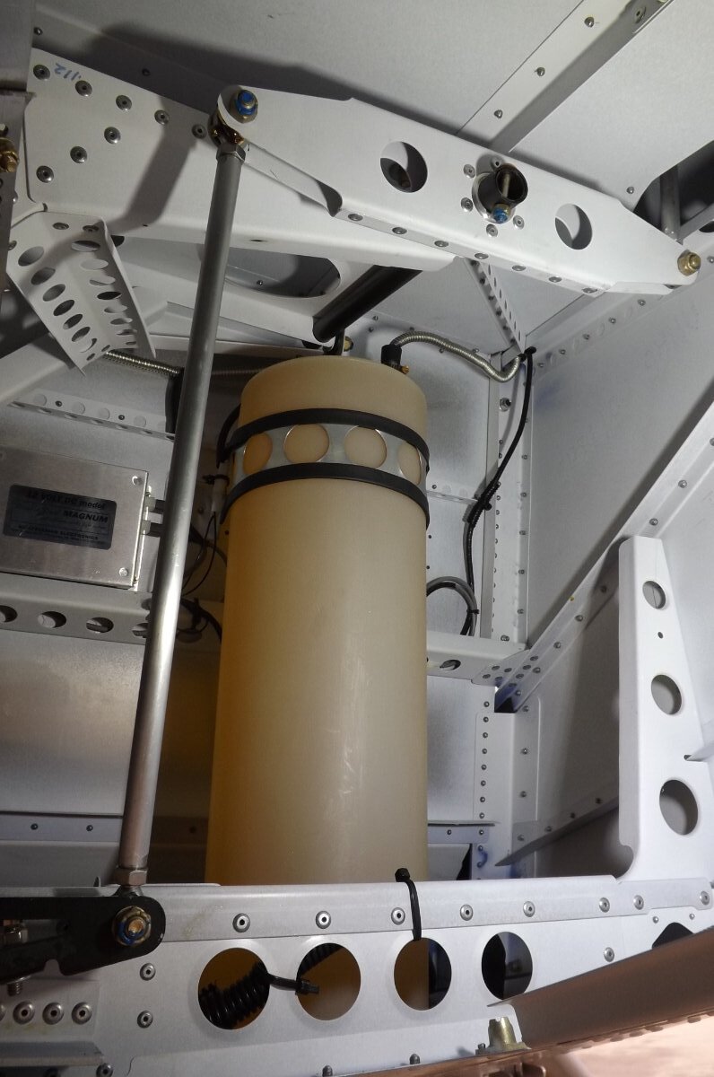
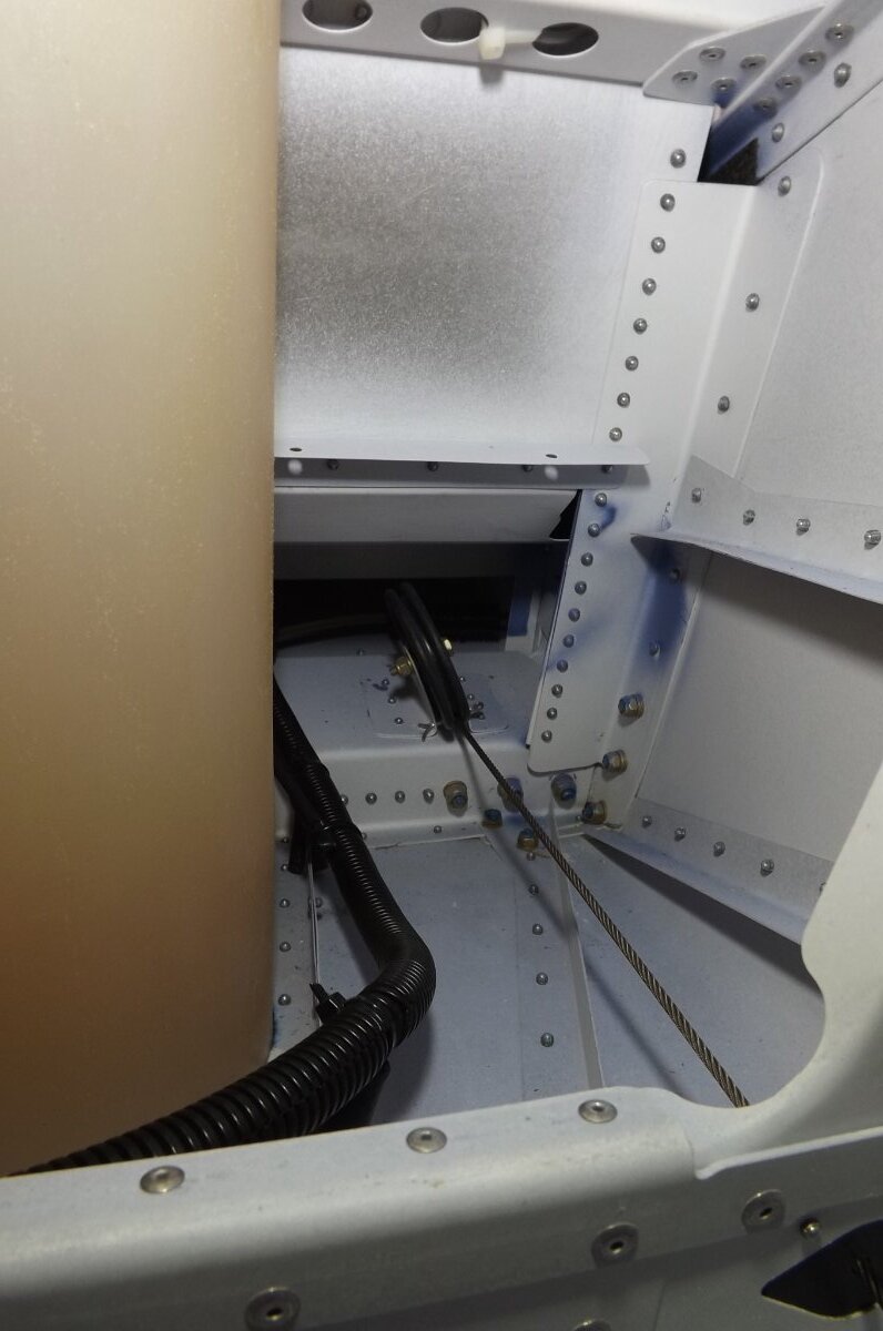
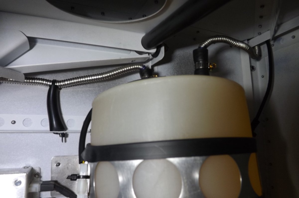
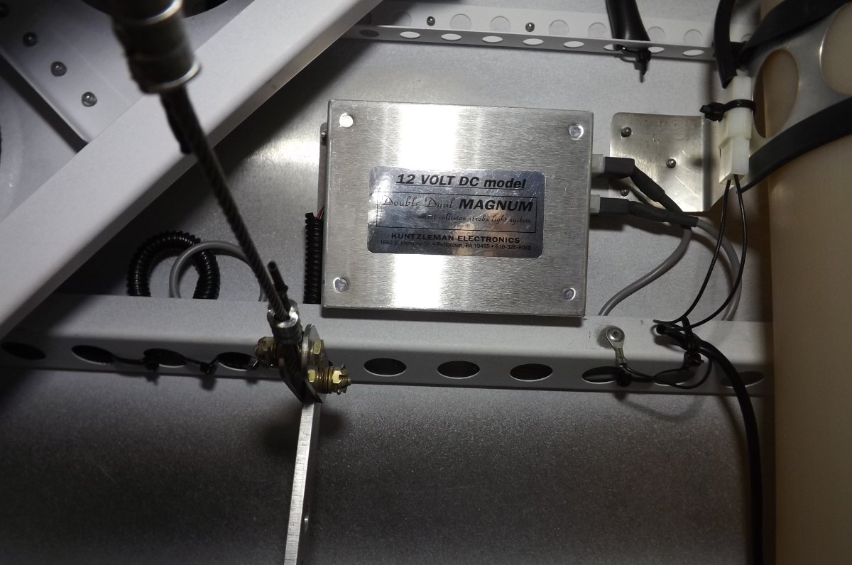
On the Sav, the breather goes into a point high in the side wall of the LH (inboard) tank: it has it's own fitting there. (I guess it could also be teed into the upper sight glass fitting, provided that tube was level or uphill from the tee to the tank, that would be one less fitting in the tank.) On the pics the RH top tube is the fuel coming in, the LH top tube is the breather. The breather pipe does a a very tight bend under the mixer, that steel pipe is excellent as it holds the bend you put in it, and bends without collapsing. You can also see the low fuel switch wiring lug riveted to the crossmember in the bottom pic. And the cable run in the black corrugated stuff at the base of the tank in the second pic down is the main battery + and - cables and the lead from the low fuel switch going forward. The other visible wiring is from the Magnum box to the wingtip strobes.
-
On the Sav, the breather goes into a point high in the side wall of the LH (inboard) tank: it has it's own fitting there. (I guess it could also be teed into the upper sight glass fitting, provided that tube was level or uphill from the tee to the tank, that would be one less fitting in the tank.) On the pics the RH top tube is the fuel coming in, the LH top tube is the breather. The breather pipe does a very tight bend under the mixer, that steel pipe is excellent as it holds the bend you put in it, and bends without collapsing. You can also see the low fuel switch wiring lug riveted to the crossmember in the bottom pic. And the cable run in the black corrugated stuff at the base of the tank in the second pic down is the main battery + and - cables and the lead from the low fuel switch going forward. The other visible wiring is from the Magnum box to the wingtip strobes.
-
Just sits on floor skin, no reinforcing, upper part is strapped to panel behind RH seat. Haven't seen one with 3 top fittings. Maybe one for each of the tanks, and the small one added later as a breather. On the Sav the breather goes into the LH inboard tank high up (and the fuel return from engine goes same place on the RH tank.) Having said that, no need for 3 fittings: normally one big one is used to bring fuel in from 1 or multiple tanks, the other big one is the breather. The low fuel switch is a simple reed switch, and when it is made (fuel low) it connects the wire to the aircraft hull. So that terminal there is normally riveted to the hull right next to the tank. The indicator at the panel has 12V on it all the time, the level switch completes the circuit by switching on the negative side. The indicator test button on the panel does the same thing: completes the circuit on the negative side. Not the best pics, sorry.
-
RFguy, if it hasn't been touched on here before: have you checked that your callipers are floating properly, so the pads are pressing fully on both sides of the disks? The brakes on my aircraft are very basic, the float is provided by dowels that are a very neat fit, with no way of cleaning or lubricating without dismantling. And float can be hard to check too: the brake can look okay with pads on both sides contacting the disk even if the calliper is no longer floating. So far, my braking is excellent, but if it starts to fade that will be the first place I will be looking.
-
OK - who is ready to do this in Australia?
IBob replied to SGM's topic in Student Pilot & Further Learning
Indeed. We have long since reached peak amaze. Which would be amazing if there was any amazement left in us........) -
OK - who is ready to do this in Australia?
IBob replied to SGM's topic in Student Pilot & Further Learning
You'd want to be confident the lines weren't painted on the road after a Friday lunchtime or on a Monday morning.......... -
I like the sound of your auto fuel pump, Mark. I would suggest the pump still needs to be started then stopped in manual prior to engine start and auto operation: (Part of my) prestart goes like this: 1. Check tank levels. 2. Check all fuel valves and isolator are set as required. 3. Master switch on. 4. Fuel pump on: check fuel pressure rises > 2PSI. 5. Fuel pump off: check fuel pressure falls to 0. This checks that the fuel return, which has a very small orifice, is not blocked. The fuel return is essential to avoid the possibility of vapour lock in the fuel delivery system. Since the fuel pump has a built in check valve, if the fuel return is blocked the pressure will not fall when the pump is turned off prior to engine start.