IBob
-
Posts
3,070 -
Joined
-
Last visited
-
Days Won
26
Content Type
Profiles
Forums
Gallery
Downloads
Blogs
Events
Store
Aircraft
Resources
Tutorials
Articles
Classifieds
Movies
Books
Community Map
Quizzes
Videos Directory
Everything posted by IBob
-

Question about Savannah wiring loom
IBob replied to Marty_d's topic in Instruments, Radios and Electronics
Marty, you already have your alternator yellow wires connected to the voltage regulator, right? -
Crikey, that is a long one, in this age of ever shrinking attention spans! But I am interested, so mental note for rainy day......
-
E-Props ...who has first hand experience with these
IBob replied to eightyknots's topic in Engines and Props
100hp 912 gearbox ratio is 2.43 : 1 so 5000 = 2058 5100 = 2099 5200 = 2140 5300 = 2181 5400 = 2222 5500 = 2263 5600 = 2305 5700 = 2347 5800 = 2387 -
Thank you, Meglin. I think here that would also be calendar time and what you call resource would be flight hours.
-
That's not a canyon turn, THIS is a canyon turn!
IBob replied to Garfly's topic in AUS/NZ General Discussion
Agreed, Garfly. I found that old clip quite wonderful..............) -
That's not a canyon turn, THIS is a canyon turn!
IBob replied to Garfly's topic in AUS/NZ General Discussion
Yep, it's the slippery slope of More Is Better. Quite aside from questions of legality, and the realisation that as a cheap drunk I might take a trip and never make it back, it was what deterred me from various drugs when various drugs were all the go: the real fear that altered states would render everyday life grey and bland by contrast. -
That's not a canyon turn, THIS is a canyon turn!
IBob replied to Garfly's topic in AUS/NZ General Discussion
Yep the camera work and editing is all getting so slick, it's losing it's impact. I just watched a similar Red Bull thing: lots of short fast clips, often from angles that accentuate the action, and while it ought to be more exciting, it somehow isn't. Also: at the back of the mind lurks the realisation that it is now so easy to CG or C modify this stuff...it just becomes a big shrug. -
I've been on DC6s that used water injection on very short strips. I was told it was to boost the engine output, while also helping improve cooling. I would think the combustion pressure in the engine would increase: I would want to be confident the engine could manage that
-
Hi Meglin, I am interested in what you have written here, but I am not understanding part of it. I am guessing by resource you mean working life? Also 'bends and tends to break...'? Can you check your translation? Thanks.
-
Battery options - Rotax 912ULS
IBob replied to Marty_d's topic in Instruments, Radios and Electronics
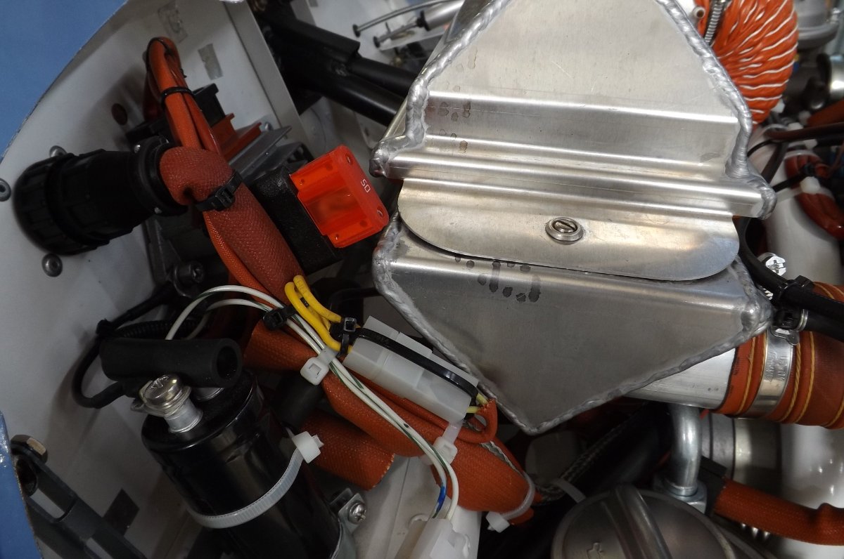
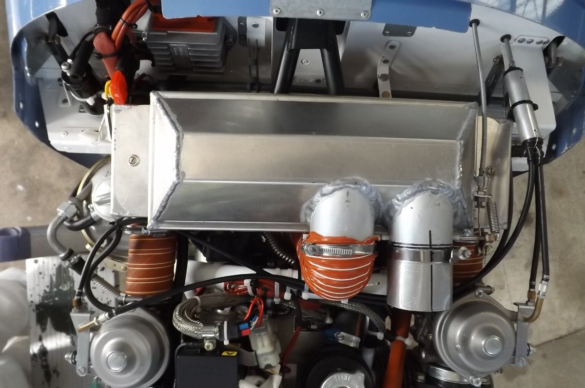
An aside regarding the charging and trigger coils that provide the energy and the timing for the ignition: off topic, and has been mentioned before, but this seems like a good place to revisit it. The gap between these coils and the trigger magnet cams on the flywheel is critical: too wide a gap has been seen to give poor starting, even with a well maintained engine and battery system. This gap is given as 0.4 - 0.5mm (16 - 20 thou) for old type coils, 0.3 - 0.4mm (12 - 16 thou) for new type coils. It is not hard to locate these fittings on the back of the engine, but the gotcha is this: Because the feeler gauge is between the strong magnet of the cam and the coil, it will stick tightly to the cam, and feel like a good snug fit, even if it is not. Furthermore, when 'feeling' from the side' the feeler gauge has to be flexed to fit the gap, which also gives the illusion of a snug fit. We found it easiest to use the brass feeler gauges which are part of some sets; also to remove (unscrew) the required gauge from the set to give better 'feel'. In the absence of brass feeler gauges, it would be essential to ensure the next size up gauge was 'no-go'. -
Battery options - Rotax 912ULS
IBob replied to Marty_d's topic in Instruments, Radios and Electronics
Plus one for the cranking: There is no electrical connection on the 912 between the battery and the ignition systems. The electricity for the ignition is generated by coils in the stator as the engine rotates, and the engine must rotate at a sufficient speed for that to happen. So, to start well and reliably, the engine needs to rotate briskly. -
That, and hold them still at the front while doing them up from the back...
-
https://www.theguardian.com/world/2021/aug/11/canada-helicopter-dairy-queen
-
Apparently they are a great aircraft, and unusually enjoyable for the pax too, as they get to see over the top........)
-
SIAI Marchetti take-off crash (Idaho, July 2021)
IBob replied to Garfly's topic in Aircraft Incidents and Accidents
Yep. Which is why I think something shifting back under the front-to-rear-stick torque tube with the initial acceleration and stick back takeoff, making it then impossible to get the stick forward, is a possibility: all the preflight checks would go just fine. -
SIAI Marchetti take-off crash (Idaho, July 2021)
IBob replied to Garfly's topic in Aircraft Incidents and Accidents
Indeed. And if your life depended on it? Furthermore, that aircraft never reached any great speed, so the principal force acting on the trim would be from the propwash... -
SIAI Marchetti take-off crash (Idaho, July 2021)
IBob replied to Garfly's topic in Aircraft Incidents and Accidents
I think he's barking up the wrong tree entirely here: while the dual trim tabs will provide a powerful trim, I would be surprised if they would overpower the pilot's ability to move elevator down, especially as it slowed in the climb. Here's an alternative possible scenario: Note the horizontal green tube that links the front stick to the rear stick, close to the floor, clearly visible at 2.00 in the above video. With stick back, that tube is raised, pushing the stick forward will lower it. And any solid object that has slid back during takeoff, lodging under that bar, will prevent the pilot moving the stick forward. Something like the fire extinguisher, visible at 0:33 would do it. And that's all it would take.... -
Yes, you did splendidly! Though several others here are a bit hot and cross...which invariably seems to be part of these little brain teasers too.........(
-
Incorrect angle of a attack on the wings would also do it....but that's pretty much the same as saying the empennage is incorrectly aligned with reference to the wings.
-
Skippy, your exceedingly large packed lunch has slid to the tail of the aircraft while you were executing that blinding climbout.......)
-
So, is the stick full forward...or is it forward as far as it will now go???
-
Battery options - Rotax 912ULS
IBob replied to Marty_d's topic in Instruments, Radios and Electronics
Yep, probably a bit on the light side. It's classed as a motorcycle battery. My 912 starts first pop, so the battery has never really been 'tested'. -
Battery options - Rotax 912ULS
IBob replied to Marty_d's topic in Instruments, Radios and Electronics
Unibat CBTX20CH-BS 12V18AH lead acid came with the kit, I've emailed for the spec, including weight. Works fine. Located behind the pilot and could be further back as the Savannah S tends to run out of elevator authority on landing rollout. Poor starting risks expensive damage to the 912 and good starting requires the engine to turn over briskly. So I fitted a battery negative cable (rather than relying on the aircraft hull), as others have done. -
Battery options - Rotax 912ULS
IBob replied to Marty_d's topic in Instruments, Radios and Electronics
Definitely put the battery behind you: it'll help with low speed elevator authority on rollout. -
Battery options - Rotax 912ULS
IBob replied to Marty_d's topic in Instruments, Radios and Electronics
The battery + goes to one terminal of the starter solenoid. That's the fat red cable. The output of the voltage regulator (B on the regulator) that keeps the battery charged goes to the the same terminal on the starter solenoid. Make up a short cable with lugs on the ends, and connect the + side of the capacitor to that same terminal on the starter solenoid. Make up another short cable with lugs and connect the - side of the capacitor to your negative bus point. The usual place for the capacitor in the Sav is at the RH end of the front shelf that carries the throttle bar etc. Best wait until you have the throttle bar etc in place, on the Sav there's not much room there.