dan tonner
-
Posts
125 -
Joined
-
Last visited
Content Type
Profiles
Forums
Gallery
Downloads
Blogs
Events
Store
Aircraft
Resources
Tutorials
Articles
Classifieds
Movies
Books
Community Map
Quizzes
Everything posted by dan tonner
-
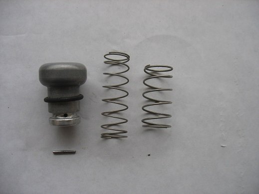
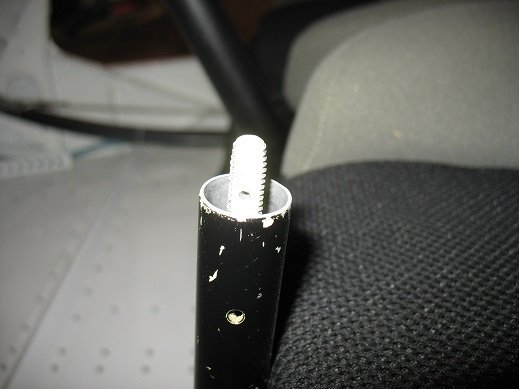
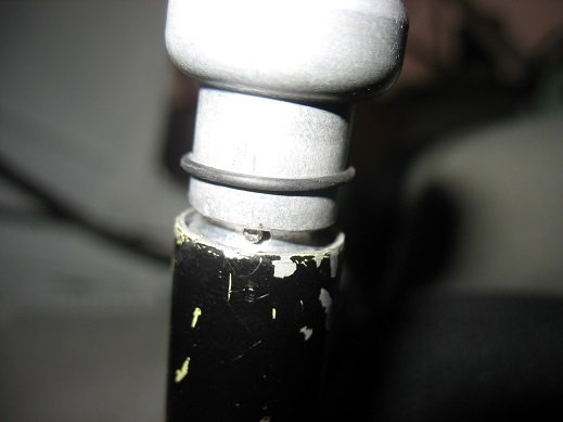
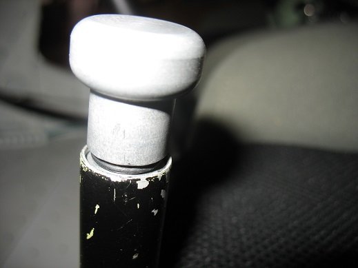
Hello Bill; I saw your post and thought you might want to have a look at a modification (or two) I made on the flap lever and spring following an incident where the original flap lever released during a final approach. I have also added a "Mark Kyle" flap lever bracket as well. The two springs slide over one another and increase the force on the mechanism that locks the lever in position. Did someone unscrew the knob from the lever resulting in the loss of the original spring? (Happened to me a couple of times before I made this modification.) Fly safely; CanadaDan A second spring was added internally to the flap lever push button to help prevent unintentional flap lever release from the locking grooves in the floor-mounted bracket. Additionally, the threaded knob and actuating rod inside the flap lever were through-drilled at the groove of the knob. A pin is kept in place by a suitable O-ring and prevents the knob from being unscrewed unless the pin is removed.

-
Sounds just like the discussion regarding renewals here in Canada. One has to appreciate the scope of duties in government offices: nails to be filed, coffee to be drunk, holidays to be planned, and so on....... CanadaDan
-
This is what I have been using - along with 10 liter plastic fuel cans and a Mr. Funnel. I have a sheet of bubble wrap that I set on the wing longeron next to the filler, set the plastic jug on it, slip in the pump and operate the switch with one hand and steady the funnel with the other. I changed the two "D" cell batteries after three years. The hose from the pump appears flimsy but has proven itself over the six years I have used it. The cost: $15.00 plus tax. I purchased two in 2016 because they looked a little cheaply made. The second one is still in the box and has never been used. Canadian Tire store as well as at other outlets -(Princess Auto and Home Hardware) NOTE: not all versions of this type of pumpare approved for gasoline. CanadaDan fuel pump.docx
-
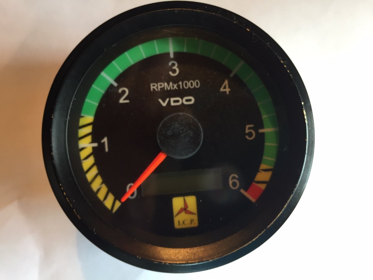
Thanks for the followup reminder, Farmpilot. The repair was a complete success. The main issue was getting enough of the crimp relaxed around the plastic case to free the faceplate. Patience and proceeding in very small steps was a key. The Hobbs/Tach is reinstalled (the Hobbs remembered the last reading) and I had a few flights since where all worked well. Thanks again so much for the advice and encouragement. CanadaDan
-
KGWilson and Farmpilot; Thanks for your replies. The replacement LCD screen is due to arrive today (along with Hurricane Fiona). Assuming my hangar and airplane withstand the meteorological assault, I'll let you know the results of the repair. I have already removed the tach, carefully prised open the case and removed the original screen. (Before ordering the replacement, I also snipped 1/8" off the end of the ribbon connector and reinstalled it - a trick I learned from repairing microwave oven keypads. However, this time it didn't fix the problem - the display was still as spotty and unreadable as before.) Farmpilot; I loved the video - that is one fellow I'd let work on my airplane anytime! I'll let you know how I make out with the fix. All the best; fly safely, CanadaDan
-
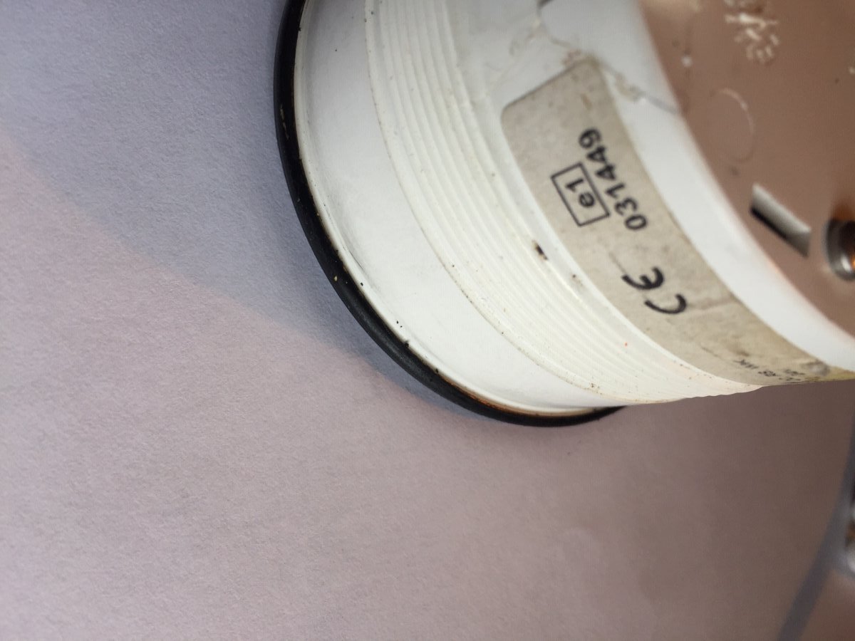
Thanks for the reply Farmpilot. The front bezel of my Tachometer is crimped over a lip on the front edge of the case; if this was the situation with your tach, how did you manage to un-bend (then re-bend) the bezel without seriously damaging it? (Photos attached) CanadaDan
-
The Hobbs readout window on my Tach/Hoibbs gauge began flickering and became unreadale (partial numbers) during a flight yesterday. Because the Hobbs gives a readout as soon as my battery master is "on" and the key is in the "run" position, it appears to be simply a real-time clock using active 12v power. The pink wire that comes from the Voltage regulator's "L" position provides the signal to both the Hobbs and the red "charge" lamp on the panel. The Tach, of course gets its signal from the RPM pick-up coil on the flywheel. There are no issues with the Tachometer or any of the other gauges or electrics. The red ":charge" lamp works as it should and shuts off as soon as the engine is running.The Tachometer ground wire and the signal wire (pink) from the regulator each show continuity from end to end. Is there a way to reset the readout on the Hobbs window? The gauge itself cannoity be opened - it has a crimped bezel holding the glass front to the plastic body. Could this be an issue with the voltage regilator? Anyting else? Rather than replacing the gauge, I would probably just be more vigilant with my watch and start-up and shut-down times. Or install a simple 12v digital clock that resets to zero on shutdown. Suggestions welcomed, CanadaDan
-
Honest cruise airspeed to expect on a Savannah S?
dan tonner replied to Jim Bair's topic in Savannah
Hi Jim; I have a 2010 VG XL tricycle and I see 85 MPH on the airspeed indicator at 5000 RPM. Dan -
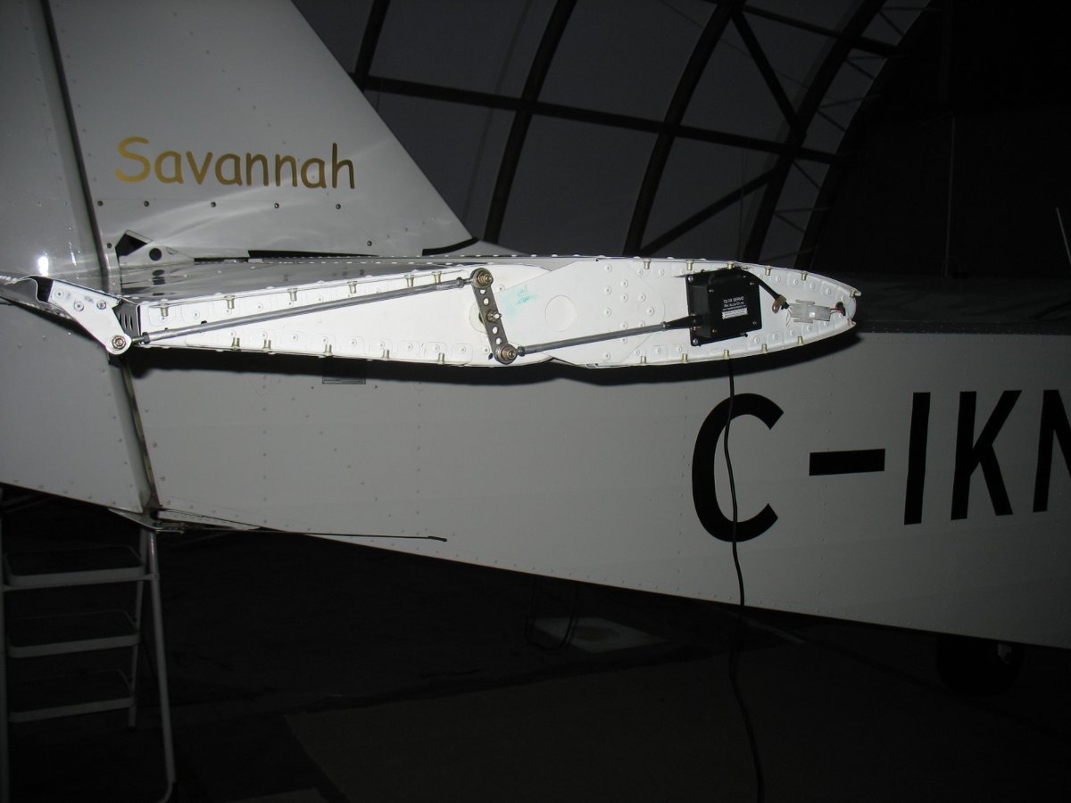
Bob: my trim indicator is a single lighted bar that moves up and down a 10-step “ladder”. I set it so that in cruise, the middle “rung” (sometimes both segments 4 and 5 ) are lit up. I had already changed the offset servo connections to “straight-on“ clevis connections to the push/pull trim control rods on both sides of the horizontal elevator. It required a small repositioning of the servo – see picture (full nose down position shown in attachment). Keeping in mind the indicator displays the servo ram position and not the actual trim tab position, here’s how I set the indicator: · I adjusted for cruise trim in flight then landed without making any more trim changes; · I secured the stick in a centered position and measured the trim tab deflection; · I pressed the trim rocker switch to move the indicator to the center position, then adjusted the push/pull rod lengths on both sides to achieve the previously measured trim deflection. Having shared all this, I believe this procedure would actually worsen your situation. Currently, in cruise configuration, you still have 7 “segments” of nose-up trim available. Were you to “center” the indicator to your cruise configuration you would reduce the “available” nose up trim segments to 5 and consequently require even more backpressure with flaperons engaged. I think Mark has it nailed; you may be a little nose heavy. When I press my tail down, I pass the “balance point” when the skid is about 6” above the level surface; when the skid is on the ground, it carries only an ounce or two of weight. I have the battery (and and about 25’ of gauge 4 wire leading to and from it) mounted in the tail; My tires are still the stock Carlisle “yard machine” tires…do you have a Condor on the front as well as the mains? I’ll be watching to see how you make out…. ANDY: Like Bob, I have Mark Kyle’s flap lever bracket installed. The original required the lever to be awkwardly pulled into the pilot’s crotch for full flaperons. During a test flight just after completion, my plane suffered a hard landing when the lever “released” during the landing flare (according to the pilot.) I suspect the awkwardness of the original lever contributed to a failure to fully lock in place. Broke my heart and cost lots in terms of time and money for repairs. I try not to look at those photos. I found with full flaperons (even with Mark’s 4-position bracket) I was uncomfortable with reduced rudder / elevator authority. Perhaps with experience and practice I will grow into that configuration, but for the time being, I’m happy with longer strips and 45 – 50 mph touchdowns. All the best, Fly safely. CanadaDan (Dan)
-
Hi Bob; You seem more concerned with the nose-down attitude at full flaps than with the extra force required to keep the nose where you are comfortable at full flaps. Is it possible that because you need to “pull” harder on the stick you end up thinking you are flying at a nose-down attitude? You mentioned that in cruise, your trim is at “3 bars”; but you didn’t say whether this was nose up or nose down. Since the RayAllen electric trim works opposite to the Anti-balance mechanical trim, depending upon whether you have a nose-up or a nose-down “3 bars” trim at cruise, this will affect control “feel” at full flaps – especially if you are three bars from full nose-down trim in cruise. The anti-balance function would have the trim tabs way up (trying to push the nose down) when you are using flaps and trying to hold the nose up with the stick. Rather than over thinking it (I probably already did); consider adjusting the trim so that the bar is centered when you are in cruise (with your “usual” weight-and-balance configuration). This works for me, along with NEVER using full flaps – but that’s another story. As for the “factory” settings, something as simple as where you mount the battery (mine is in the tail) will determine the “right” trim settings for your particular build. All the best, vfly safely, Dan
-
or "XLVG" :-)
-
Hi eightyknots; I've attached a link to Transport Canada's "Listing of models eligible to be registered as AULAs" Listing of Models Eligible to be Registered as Advanced Ultra-Light Aeroplanes (AULA) (canada.ca) Under ICP, you'll notice there is the "Savannah" (with two listings reflecting different MTOWs), the "Savannah VG"; the "Savannah VGW" and the "Savannah S". There is no "XL" or "VGXL". But, that's Canada. CanadaDan
-
IBob and Onetrack: Thank you for the replies: Dianne McNamara at Punkinheadair sent me this photo of a cover (along with another fitted to the older model Savannah VG). She was very helpful and spoke of a newer type cover fabric called WeathyerMax Surface Guard which is touted to be lighter weight, has a knitted polyester liner and has superior waterproofing and breathability characteristics. All for $640.00 plus shipping. It gives me a good place to start. All the best, fly safely, CanadaDan
-
Greetings all; As summer approaches the Great White North, I am anticipating flights which will have my Sav XLVG tied down, overnight. I have the fabric to make a cabin / cowling cover but no pattern for my particular airplane. I started this topic hoping to find a Savannah owner who has already been down this road and would be willing to share such a pattern with me. Fly safely, Canada Dan
-
Hello Microman; I built my Savannah XLVG in 2012 and discovered this Recreational Flying site during my build. It is unquestionably the voice of authority when it comes to the ICP Savannahs - all models. Within the site, I have often read comments that effectively say ...if the predrilled holes don't line up, you've done something wrong... I now add my voice to the same counsel. If you need to use a drill to get the holes to line up, you may need to STOP - BACK UP - RECHECK. As troublesome as the assembly manual is - and as unhelpful as the parts packing may be - the kit itself has been engineered to near perfection and appears to undergo even further refinements on a regular basis. Oversize rivet holes will come back and bite you and substituting a larger size rivet is not always possible or advisable. Because the aluminum is so soft, the use of a punch or an awl to "pull" the holes into alignment will usually distort the hoes as well and is not a good idea. A bit of a "perfectionist" myself, my kit took 1300 hours over about 14 months to build, working alone. Painting was contracted out. I am still in awe of the accuracy and detail used to produce, shape and drill the parts I received in my kit. I cannot recall a single occurrence where uninstructed drilling was needed although there were many times I had to find a better way to pull, push or tension skins to get all holes in alignment. I too just love flying the airplane and have always wanted to build another Sav - an "S" kit. All the best; fly safely, stay safe. CanadaDan
-
I bought and installed an MGL V6 in my Rotax powered Savannah in 2012. Great product with even greater product support. I was in touch with MGL Avionics in Torrance California for installation and operational issues (my fault, not theirs) and got great product support right from the horse's mouth - so to speak. I believe Michigan Avionics is now doing much of the product support for MGL equipment and they oversee a "Customer Support Portal" you can join from their website. www.michiganavionics.com That being said, my "go to" guy was Matt Liknaitzky at MGL Avionics in Torrance, California. A call from Mexico won't break the bank (424) 358-4510 and if Matt can't help you, he can steer you to where you can get it. www.mglavionicsusa.com is their website. FWIW: in my case, all engine-related radio transmission/reception noise was eliminated by properly grounding one end of the wire sheath covering the generator wires and the charging wires coming from the stator and going to the ignition modules and the rectifier/regulator, respectively. Stay safe; fly safely. CanadaDan
-
The promised followup: First - the summary: The problem was failed insulation on the two charging wires from the stator to the modules. The insulation over the wires was more like “putty” than “plastic” and at the point where they were zip-tied near the modules, out-of-phase voltage from the two coils seems to have been able to jump the compressed insulation and cancel. I believe this issue was the reason for SB 912-026 back in 1999 and my engine was never made compliant. Second - the test results: A) AC Voltage across each red lead to engine ground at cranking speed (modules disconnected) 5.6 VAC each side. (when wiggled – VAC fluctuated to 0). Bob: I also did the test with the modules connected – 4.55 VAC on each side; - as above, when the wires were wiggled, VAC fluctuated to 0. B) Resistance across a red lead to engine ground – 3.6 OHMS each side. Flexing the wires did not seem to make any difference. (Possibly redirecting the reading across the crossed wires and through either coil to ground? ie: no change) C) Resistance across the two disconnected red leads: 6.7 OHMS; when wiggled, the reading would change to 0 OHMS – indicative of crossed leads. NOTE: the 6.7 OHM reading is a measurement down one red lead through its charging coil to ground and then up through the second coil and its red lead. The resistance with the coils in series is summative: 3.6 + 3.6 = 6.7 + line/connection resistance? (The resistance would not decrease as I had erroneously speculated.) D) I did not perform the "fuel spray" test after I finding the “crossed” leads. I separated the leads beyond the zip-tied connector. (no fuel sprayed – no insurance claim 🙂) I proceeded to the next test. E) I removed the set of plugs served by the one connected module and, using sections of single-strand 12 ga copper house wire, I grounded each sparkplug and reconnected the caps. When the starter was engaged (higher RPM with plugs removed) there was lots of spark, in sequence, at every plug. After connecting the other lead to the module, the second charging coil produced identical results. F) No rats; no squirrels. (I didn’t really look….) So, where am I? I pushed back the wire mesh sheath and separated the charging wires to a point halfway between the last two clamps on the motor. I cut the wires here and spliced in two lengths of 22 ga red automotive wire and triple shrink-wrapped the soldered connections. I pulled the wire mesh back over the joint and along the wire as far as it would go – adding a second wire mesh sheath, shrink-wrapped at the joint, to gain a couple of inches of length. I secured the ”new” wire at the second clamp on the motor. The plan was to ensure there would be no movement from the charging coils all the way to the sparkplug coil bracket – especially where the “original” stator wires were still intact. I added two new female bullet connectors and reassembled the ignition unit. Because of heavy rain and muddy apron conditions, I did not roll the plane out of the hangar to attempt a start - and had to travel home (about 200 km away). I am certain it will start (on the first try) when I get to my hangar - I will only add to this “already-too-long” thread if it does not start. It is clear I need to either: · repair the “original” stator by replacing the red charging wires (and probably the yellow “generator” wires as well) right back to the coils, or, · replace what I have with a good second-hand “newer-style” stator. (I am not ready to purchase a new stator for US $1500.00 (plus, plus)...yet... Thanks everyone for “kicking in” – Stay safe; Fly safely. CanadaDan
-
Well. gentlemen; I have a plan for arrival at my hangar sometime this week. Below is a summary of some of your suggestions and my additions, deletions and thoughts regarding what to expect. Should you notice flaws in my reasoning (...my wife tells me from time to time that this is possible...) please jump in. Once I've completed the "trials", I'll update you all here. As you will probably notice; I am leaning heavily towards "stator failure" as the culprit with my engine and may be looking for a good used P/N 996 539 or P/N 888 675. Stay safe. Fly Safely. CanadaDan Engine checks in search of the cause(s) of sudden engine stoppage. NOTES: Mag switches were checked for proper operation. Fuel system was checked for quality, supply and flow control; carb bowls properly full. The result of any test may preclude the need for any number of the other tests. A) Measure AC Voltage across each red lead to engine ground at cranking speed. (Leads disconnected from modules.) · 5 – 7 VAC on each lead: Specification measurement; All OK. NOTE:: during B & C tests, I will flex the harness at pinch points. Reading changes will represent failure. B) Check resistances across each red lead to engine ground: · 3.2 – 4.5 OHMS on each lead: Specification measurement; All OK. · 0 OHMS: Short to ground (failure) · INFINITY OHMS: broken lead wire (failure) C) Check resistance across the disconnected red wire leads from the charging coils: · 3.2 – 4.5 OHMS: one lead wire is shorted to ground (failure) · INFINITY OHMS: broken lead wire with no grounding or shorting of leads. (failure) · 0 OHMS: shorting of leads or possible grounding of BOTH lead wires. (failure) · SMALL RESISTANCE: (half of 3.2 – 4.5 ohms) All OK. (measures resistance from lead through the first coil to ground then back through the other coil and second lead.) D) Attempt to start the engine while an assistant sprays fuel into the intake end of the carburetor(s). Any detonation indicates the presence of spark. Explosion and fire indicates the need for insurance. E) Ignition on; module(s) connected. Engage the starter with the top plugs removed, connected and grounded while an assistant looks for spark at the gaps. Results will also depend upon which modules/sparkplug coils are connected. F) Look for rats & squirrels in the exhaust pipe.
-
WOW! I think we're ready to ask NetFlix or Prime Video to produce series for us! So much to talk about. So little time. 😃 Bob - your last post describes the perfect scenario for instantaneous failure in both ignition systems - shorting across the two charging coil leads - the exact reason for the Rotax SB 912-026 in December of 1999. My first "test" at the hangar will be a close look inside the wire mesh sheath over the charging coil wires ...followed by checking the resistance between the connectors of the two "red" leads. And, if the stator were never replaced, my engine has had 23 years reach the point of collapse. Then I'll look for a squirrel in the exhaust pipe. Mark: if it weren't for Wikipedia I'd still be hung up on CRO but I'm still trying to get my head around: the square Root of the Mean of the Square. I get over my head quickly with electronics. Fortunately, I had no problem with the chart of multimeter AC Voltage vs RPM from Blueadventures - which was essentially confirmed by you. Thanks to all...keep safe, fly safely. I'll post my findings. (JG - this was your thread......still reading?) CanadaDan
-
Blueadventures..... ....My engine is a 1997 912 UL - The connection at each module involves 9 wires as follows: 1. one 4-pin plastic connector (feeds from the 2 trigger coils that feed that module), 2. a bullet-style connector for the module's mag switch, 3. a bullet-style connector for the charging wire from the stator, 3. two bullet-style connectors which feed signals from that module to its pair of sparkplug coils, 4. a black wire ground for the module which is tipped with a ring connector. NOTES: 1. My sparkplug coils ground directly onto the 1 / 3 intake manifold on the engine - on newer versions, these ground wires feed back into the modules. 2. My serial number is 4401811 - this engine was included in group A of the Service Bulletin 912-026 (December 1999) dealing with stators whose leads which were subject to insulation failure. I have just learned how to examine the wiring to determine whether or not the stator on this engine was replaced as mandated in the bulletin. The change was to have been done "at the latest" buy April of 2000. 3. There doen't seem to be a completely accurate diagram of my ignition setup in the latest version of the Heavy Maintenance Manual. Fig. 74-18 on page 25 of 74-00-00 purports to be the "old style" UL version but shows the sparkplug coil ground wires feeding back into the module. The module/ sparkplug coil / sparkplug assignment is like mine. Fig. 74- 21 on page 31 of 74-00-00 illustrates the "older style" 914 UL/F version. Although the sparkplug coil grounds are shown converging to a single engine groundpoint, the module / sparkplug coil / sparkplug assignment is specific to the 914's and not the 912's.
-
Thank you all again for your further input - I am preparing a list of tests to do on my next trip to the hangar. When I've resolved the issue I will post the solution and the final path that led to it. M61A1 - one amp; wiggle the wires....got it. (What did M61A1 evolve from?) Bob - am I correct to assume I would connect the AC voltmeter in series between one charging coil wire and its module in order to get a "dynamic" reading while cranking on battery? (I note Blueadventures appears to do these checks with the meter between the coil lead and ground whether cranking or during an engine run on one mag while the other is being tested.....unless there's another way to make it turn at 5000 RPM...🙂) Skippydiesel: I am still hoping that "simple" solution might involve removing a dead rat from my exhaust. All the best to each and all; CanadaDan
-
Thank you (all three of you for taking the time to offer suggestions...) Mark: Correct me if I've misunderstood you but, as long as there is no contact between the two CDI coils "hot" leads and ground, no break in the wire or windings and a good ground at the other end, I will see "specification" resistance through these coils of 3.2 - 4.5 ohms. (not "zero" reststance) (I get readings of 3.6 and 3.7 ohms on the static engine.) I do understand you to say that the current could jump across a tiny "gap" to ground before reaching the modules when the engine is spinning if the wire insulation is deteriorated and being compressed at the hold-downs. That is one scenario. BUT; WHAT WOULD HAPPEN IF CURRENT CROSSED FROM ONE POSITIVE LEAD TO THE OTHER POSITIVE LEAD DUE TO INSULATION FAILURE INSIDE THE WIRING SHEATH? (I'm trying to understand why all resistance checks are "good", the module is good and trigger coil gaps are good but the engine won't make spark. I haven't measured the AC from the CDI coils (disconnected modules) with the engine turning on the starter. I don't know what voltage or amperage to expect and my multimeter has limited current capability; this test is not described in the Heavy Maintenance Manual and I don 't know how to properly set it up. SkippyDiesel: You have summarized where I am headed quite nicely. M61A1: Can you recall what the "very low" resistance readings of your failed stator were? I am still getting specification readings from each (which happen to be "very low" at a little over 3.5 ohms). It is possible that there is a crossover between the "hot" leads either at standstill or when the engine is turning. I don't know what effect this would have on the resistance reading(s) across the CDI coils since they are quite low anyway at 3.3 - 4.5 ohms. Thanks again foir the inpou. Stay safe. Fly safely. CanadaDan
-
Thanks again SkippyDiesel; I wasn't joking about the squirrel in the exhaust...my hangar is rural and I have trapped a squirrel attempting to set up a home in the hangar before.... and, "bin there; done that with blocked chainsaw and lawn mower exhausts (carbon though, not rodents.). I have removed, sanded, applied dielectric grease and reassembled the ground wires for the coils and modules. Also double checked the ground wire between the engine, battery and frame (I use a copper busbar grounded directly to my battery for the engine, all instrumentation and switch grounds.) The SB on the early 912 stators was due to an insulation issue that included the two charging wires that run to the modules. In these early stators, (and mine was one, but I don't know if it was ever swapped out) both insulated wires were bundled together inside a "fabric-type" cover that was then contained in the grounded wiremesh sheath. It seems the insulation over the copper wire tended to break down, exposing the copper wire and allowing for corrosion, and possible breakage and/or cross-connection with the other lead. The "fabric-type" layer would have to deteriorate or break to cause a short to ground. My 23 year old motor will have had lots of time for this insulation to fail. The "improved" stator has each insulated wire inside a black plastic insulation tube, bundled inside the "fabric" sheath and further bundled inside the wire mesh sheath which is grounded. I believe the wire itself also had an improved type of plastic insulation. HERE'S A QUESTION: I am trying to understand how it is that I am still getting spec-level 3.7 ohms of resistance between each charging coil lead and ground if the charging coil leads are cross-connected somewhere inside the wire sheath....it seems clear the leads are not "grounded" before reaching the coils or I would see zero ohms. Assuming those leads are cross-connected, what would you expect to see on a multimeter checking resistance from the connectors at the module end and ground? Perhaps more significant, what would happen to the current if the leads "joined" inside the sheath while the engine were running......a surge?.......a reduction of curent?......no current? Are we having fun yet? "best, CanadaDan
-
Thanks for the reply Skippydiesel; I only did the "spark test" on a couple of plugs - there was no visible spark. I will use a spray bottle to send atomized fuel into the carb intakes (air filter removed) while cranking the engine. If there is any spark - properly timed or not - there will be some form of ignition - possibly an insurance claim. = ) A squirrel trapped in the muffler is a possibility I haven't fully investigated. The "suddenness" of the engine shutdown on the runway after months of perfect performance is, I think, key here. There was no hesitation, roughness, slowing of the engine (taxiing at about 3000 RPM), and no "kickback". The engine just stopped. And no restart. A visual engine examination afterwards revealed nothing out of order. We're on the same page with your analysis. Stay safe. Fly safely. CanadaDan
-
Hello JG; I realize I am replying to a very old thread you started but which was hijacked about 2/3 the way along.... To come to the point: my very well working 912 UL just stopped while I was back-tracking for take-off. If I didn't know better, I'd have said someone flipped BOTH mag switches to ground. The engine was included in the Rotax 912-026 SB of 1999, and the logbooks do not reflect a stator change. The SB was 21 years ago and the engine has been a gem for about 1000 hours - about 300 of them, mine. Here's what I have tried without so much as a *cough* from my engine since the catastrophic failure: The mag switches were tested and found to be working. (I even tried a start with the kill-switch wires disconnected from the modules.) Nada Continuity tests were done on the charging coils and the trigger coils - I checked resistance between engine ground and each of the charging coil connectors at the modules; each checked out at 3.6 ohms - exactly on spec. I also checked the resistance of the four ignition trigger coils and all were within spec around 230 ohms. I followed the fuel supply from the tanks right up to the carburetors - disconnecting, checking and re-connecting at every stage; the final test was disconnecting the fuel lines from the carbs and opening the valve in the cockpit. "Gravity only" fuel flow was steady through all lines, the filter, BOTH fuel pumps, the "spider junction" and into a cup. I also carefully removed each float bowl and found the bowls full, the floats "floating" and the float needle adjusted properly. I checked the throttle and choke connections and found all to be as they should. I tried restarting after removing my BushCaddy soft-start module. Not a cough. I removed both modules and the BushCaddy and installed a single known-to-be-working module wired to one set of plugs through their respective sparkplug coils. When that produced nothing, I switched to the other set of coils. Nothing. I tried the other combinations of coil-to-modules connections. (I didn't expect this to work since these combinations only involved only two cylinders - it did not.) I tried these combinations with and without the kill switch connected. Still nothing. All testing was done over a period of a week and every day's testing involved a freshly charged battery. Cranking speed was normal and on cooler days, I warmed the engine with an external heat source. One thing I did not check was the trigger coil gaps - but it would seem rather odd to have all four suddenly be unable to trigger a spark. I used the same logic to excuse the four dual sparkplug coils from possible failure. Ultimately, what resolved your issue back then? Fortunately (I suppose) my problem does not seem to be intermittent; I just can't find it. Any suggestions? CanadaDan