dan tonner
-
Posts
125 -
Joined
-
Last visited
Content Type
Profiles
Forums
Gallery
Downloads
Blogs
Events
Store
Aircraft
Resources
Tutorials
Articles
Classifieds
Movies
Books
Community Map
Quizzes
Videos Directory
Everything posted by dan tonner
-
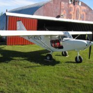
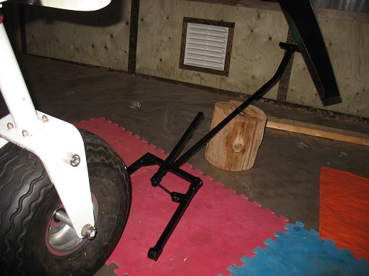
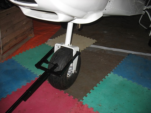
Hi Neil; I've attached a couple of pictures of a towbar a friend made to fit both his CH701 and my Savannah VGW (VGXL). The knobs on the fork are sections of 1" aluminum rod drilled and recessed for 5/16" stainless bolts. Although the towbar is made of steel (hangar use) it (or a similar arrangement) could be fashioned from aluminum tubing to save weight.

-
With a few careful cuts and folds, I modified the battery box so the battery drops into a "well" cut into the top of the original "shelf". I added some rubber padding on the bottom and sides. I elected to install a battery isolator solenoid on the positive cable in the wiring at the battery box. A ground wire from the solenoid runs to a "Master" toggle switch on the panel. Grounding that wire via the switch powers the system. This leaves lots of room to connect the battery cables either before or after battery placement and makes installation and removal a snap. My solution to battery access. Fly safely, Dan
-
Agreed; I believe the thanks belong to Valter dellaNebbia, the Savannah agent (ICP North America Ltd) in Archer City Texas. I love the way Savannah picks up on great ideas... Fly Safely, Dan
-
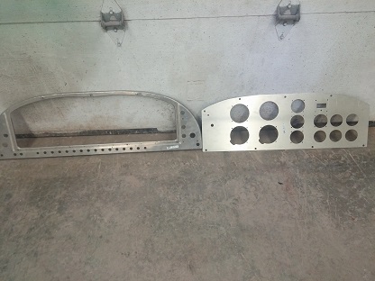
I am in the process of changing out my "original" instrument panel frame and the panel itself for the newer style of frame and panel. The newer style allows for removal of the instrument section of the panel while leaving the throttles, ignition switch, carb heat, choke and power socket undisturbed on the new-style frame. (A picture is worth a thousand words - new style frame and panel pictured.) I would like to get a copy of the assembly manual pages for the new setup showing the suggested positions of the instruments, controls, indicators etc. I note that the new style panel has nine 2 1/4" instrument holes versus ten holes on the original panel. Does anyone have this? Fly safely, Dan
-
Nicely done Rankamateur; Did you turn the nylon bush and the spacer yourself or were these supplied with the XCOM kit? I am at exactly that point with my MGL radio and would like to use the grips that came with the Savannah. Fly safely, Dan
-
https://www.google.com/search?sourceid=navclient&hl=en-GB&ie=UTF-8&rlz=1T4GUEA_enAE573AE573&q=SABIC+LEXAN+solid+uncoated+and+coated+sheet+technical+manual This manual from SABIC (the makers of LEXAN) gives detailed do's and dont's regarding the installation and cleaning of Lexan. In particular, on page 24: "Benzene, gasoline, acetone, carbon tetrachloride or butyl cellosove should never be used on Lexan* sheet." ...while on page 19: "Table 14: Recommended Solvent Cleaners" White Spirit various Petroleum Ether (BP65˚) various Hexane various Heptane various I think Hasse is on the right track.... (Interesting results with Aviation Fuel) Dan
-
This thread continues to be a valuable study for those using polycarbonate windscreens. Googling "lexan" provided a Wikipedia listing of the physical and chemical properties of "polycarbonate" which may suggest Hasse's experiments and conclusions are very astute. For example, the chemical resistance of polycarbonate is listed as "poor" to concentrated acids, aeromatic hydrocarbons, halogens and ketones; "good - fair" to greases and oils; and "good - poor" to alkalis and hydrogenated hydrocarbons (whatever that means). Chemical resistance to Alcohol is shown as "good". Wikipedia also lists the thermal properties of polycarbonate including the coefficient of linear expansion and thermal conductivity figures. Perhaps a reader with a working understanding of these indexes could suggest whether or not they contribute anything further to this discussion.
-
Hello Eric; beautiful videos and a handsome airplane. Regarding your flap position comments: You might wish to check out Mark Kyle's thread (Kyle Communications). On page 20 of his build thread you'll find some discussion and some design work he has done with the flap lever support plates. Engaging full flaps with the stock setup requires a forearm and wrist motion to pull the lever straight back towards the pilot's crotch. Mark has been able to incline the lever further forward in all positions with repositioned slots, detents and the lever pivot point. No other modifications are needed other than fabrication of new flap lever support plates. Fly Safely, CanadaDan
-
Thank you Rick; As you may surmise if you read the thread I started yesterday about undercarriage issues, it will be a few months before the throttle project is completed. When it is completed, I'll post some photos. Fly safely, Dan
-
My VG XL has experienced a couple of setbacks (no serious injuries) since being completed in the summer of 2014 - both involved a front fork tube collapse and all the associated prop/cowl damage that go along with that type of failure. The second collapse occurred when the full flaperon lever position unintentionally released during the flare. The jury is still out whether the outcome would have been better or worse had the loss of full flap occurred earlier or later during the approach. That discussion is purely academic at this point. The real issue resides with design ergonomics. Mine is not the first unintentional flaperon release posted in this forum. I am interested in other approaches to flaperon lever modifications such as the one developed by Mark Kyle and described in great detail in this forum. During the second incident my main gear also folded under causing other damage. Both forward undercarriage mounting bolts had pulled through the lower support brackets. The bolts did not shear; they remained intact although bent rearwards; the brackets, still attached to the rearward bolts (also bent), prevented the main spring from completely separating from the airplane. I offer this for two reasons: as a further example of the oft-mentioned front gear failures, and, to find out if other Sav owners have experienced similar main gear bracket failures. During initial assembly, I felt there was very little fore-and-aft support at the outer ends of the main gear but could not visualize a method to rectify this. Thoughts? Fly safely, Dan
-
Hello Rick; I am going to equip my XL VG with solid rod throttle controls based on your pioneer work using them; I have a couple of questions about the hardware. With reference to your replies to erd72's thread "Throttle Control", I plan to use a pair of eyeball-type sockets at the firewall (Aircraft Spruce 05-00958 which have the 1/4" hole to fit the outer cable sheath) with a pair of A-820 Friction Lock Controls. (An aside: all three North American Aircraft Spruce warehouses are out-of-stock on the 05-12250 "Cable Safe" items with no information regarding re-stocking. The manufacturer may no longer be in business.) I already have the R&L hand thread Aurora Stud-type Bearings, the CroMo tubing and the R&L hand thread taps for the rods. My questions: After the eyeball mount is secured on the firewall, is the sphere still free to rotate or is it clamped in a fixed orientation? How is the outer cable sheath of the control attached to the eyeball itself - that is to say, what prevents the outer sheath from moving fore and aft through the 1/4" hole in the sphere? What was the reason you opted for 6061 aluminum rods for later prototypes instead of staying with the CroMo tubing? I follow all your posts - along with those of others who have done wonderful things with the Savs - and really appreciate the Recreational Flyer forum. Regards, Dan
-
Hello Rankamateur; You will not regret waiting a little bit for that upgraded front fork support. Your plane looks great! Fly safely, CanadaDan
-
Hello Skee; I believe those two parts are the trim pieces that fit under the stabilizer on each side to close the gap between the uipper rear of the fuselage and the bottom of the empennage. Very nice work on your airplane; fly safely, Dan
-
Greetings all... I've been following this thread with some interest and thought that the article attached might help explain some of the issues we encounter with Lexan under stress. I can't confirm or refute anything the author says, so leave it to you to use - or not use - any information provided. Fly safely, Dan Lexan vs Plexiglas.doc Lexan vs Plexiglas.doc Lexan vs Plexiglas.doc
-
Thanks (again) Mark; I've written Reg with my questions. Where will I find your blog regarding fitting of the plastic tips on the ailerons, wings and rudder. I've already been through this once; although, regarding the ailerons, was not entirely happy with the results. Best, Dan
-
Hello Kyle; You've made reference to your "build blog" a few times in this thread and I'd like to have access to it. If you are willing, would you care to share it with me? I also created a chronological photo journal which followed my "first-build" log (almost 1300 hours, by the way) but I know there are better ways to do many of the assembly steps. One upgrade I'd like to make is 3-point door latches - but I don't see these listed with FlyBuy USA (I'm in Eastern Canada). Another appealing feature on the new Savs is adjustable seating - but I doubt this is available as a retrofit to a VG XL. I do have the beefed-up front gear support (but continue to have reservations about the strength of the front gear leg). Fly safely, and Happy New Yeaar. Dan
-
Hello Osteri; I'd love to see more details of your handbrake modification and a summary of your level of satisfaction with it. I have a Savannah XLVG and can't quite get comfortable with the toe brakes. In your photo I believe I see a Park Brake built in as part of the mechanism - is this correct? Do you have drawings and details you'd be willing to share? Best regards, fly safely, Canada Dan
-
This is somewhat late, but will complete the thread.... Kudos to Scott Hendry. The RPM gauge pickup coil was faulty. The pickup coil produces and delivers a pulse. That's all. It does not power anything. This being the case, I tapped into one of the ignition trigger coils with the RPM gauge feed wires. Problem solved. I did check the continuity of the RPM trigger coil wires and there were no problemwith any from the coil outwards. I managed to find a "used" coil at half the "new" price of $275.00 Canadian. (!!!!!) Thanks to all, in particular, to Scott. Fly safely, Dan
-
Here's an update...thanks to Old Man Emu, Kyle, Tom, Old Koreelah and Scott for taking the time to write and offer encouragement and suggestions. The problem persists..... all seems ok up to about 3500 -4000 RPM at which point the gauge begins to jump up - eventually reading full scale although the engine speed has only marginally increased. Keep in mind everything was working fine up until the day I had arranged for a ferry pilot to bring the plane across the head of the Bay of Fundy to her home base in Amherst, Nova Scotia - I suppose THAT should have been predictable! (*&^$#@) The pilot and I set the prop pitch to very coarse (15degrees) and he flew her home without the benefit of the Tachometer anyway. Here's what I've done and the results: each trial was done separately from the others and afterwards the tach was reconnected normally and confirmed the issue persisted. switched the tach wires - (the tach gave no reading whatsoever) installed a 10 Kohm resistor (later, a 30 Kohm resistor) in series with the sensor wires (first one, then the other) - no change - tach continued to read erratically upwards from about 3500RPM installed a 1N4004 diode in series with the blue-yellow signal wire - either no tach reading at all or (when diode was reversed) gave no reading up to about 2000RPM, then gave steady readings above this....(prop is still set to very coarse - maximum RPM about 4500) installed a 230 ohm resistor in parallel across the signal wires - no tach response. I measured the continuity across the solder joints on each of the 5 trigger coils: the four ignition trigger coils gave readings of 350 - 365 ohms (coils were not unplugged at the connectors). The RPM trigger coil gave a reading of 9 Mega ohms - the signal wires were disconnected at the time and I didn't have the presence of mind to take another reading with these connected to the tach - or even shorted to each other. (If it is a failed trigger coil, why do I see a tach response up to 4000 RPM?) I measured continuity in the signal wires across the plastic gang connector at the firewall and found (to my surprise) an 85 ohm resistance here - I don't know whether this is significant or not. These tests were done with the engine not running (of course) and all switches and ignition off. With the engine running and the signal wires disconnected from the tach, I measured the voltage across the signal wires: I saw about .27 volts at 2000 RPM rising steadily to .5 volts as engine speed increased when measured on the A/C scale of my meter. The reading was a steady 2.3 volts at all engine speeds when measured on the D/C scale of my meter. (I don't know what this means - if anything.) And here I am. No tach and very limited opportunity to borrow another tach or trigger coil to test, or even another 912 setup to which I could connect my tach. I would like to be able to "re-set" my VDO tach but there was no manual supplied with the tach and I cannot find a manual for it on the 'net. (I am very reluctant to press the "factory-set" button on the back without some direction regarding what to do next. Anybody make any sense out of all this??? Fly safely, Dan
-
Hi all; I just recently got my new Savannah XL VG (80 Hp Rotax UL) completed and in the air. I am very pleased with the results and look forward to spending the next bunch of time with her in the air instead of in a workshop and hangar. I ran into an unusual situation in that the ICP stock VDO Tachometer started performing erratically just before the first flight. It had been working perfectly through many hours of taxi trials and engine runs, but decided to start acting up when my test pilot arrived. The gauge seems to read accurately up to about 3500 - 4000 rpm, but then the needle dances to maximum and then gives readings that seem all over the board when attempting to test prop pitch at full throttle. At one point during the initial flight, the gauge needle dropped to zero for a few seconds before continuing its erratic journeys across the face of the dial. Unfortunately, ICP did not provide any manuals with the new tach but I believe (from data on the 'net) this gauge goes through a self-check each time the power is switched on. During the check, the needle on the gauge swings momentarily to maximum. All this led me to look for momentary power interruptions at the gauge - so far without finding any such problem. Have any of you encountered similar (or unsimilar) issues with the VDO Tach? Best regards, fly safely, Dan
-
Hello Rich, Absolutely enthralling photos! Here in eastern Canada (Nova Scotia) we use ice for chocks....this year, even in May. But I do have a Canadian made Tilley hat capable of safely traveling through an elephant. Washing before wearing is recommended. I expect to make the maiden flight in my VGXL kit-built this month. I will try to share some of the N.S. landscape (in pictures) with you. Fly safely; all the best. Keep those magnificent pics coming. Dan Tonner
-
Hi all; I'm Canadian, waiting for some of the snow to melt and for spring to arrive and have too much "think-time" available. Regarding the fuel leakage issues - I commented on this once before and was considering installing suitable one-way valves on each fuel supply line into the secondary tank behind the seat (permitting fuel flow INTO the secondary tank of course...) I didn't get much response. Siphoning of either tank via the vent line will not occur once the fuel level drops below the opening in the fuel cap (the tube should not dip into the tank past the cap) BUT, if fuel in one tank is at a higher level than the upper arc of the vent tube in the lower tank, the fuel in the upper tank will pour through the secondary, into the lower tank and out the lower vent tube until the level in the upper tank is below the upper arc of the lower tank's vent tube. It doesn't take much of a tilt to have the upper tank's fuel level higher than the lower tank's upper arc - in fact, I think a 15 or 20 degree lean might completely empty the fuel tank on the higher side through the lower tank's vent. Has anyone given the one-way valve a try.....I would prefer not to install shut-off valves at the wing roots. Fly safely, Dan,, spring to arrive
-
Steel bungee possibility for Savannah aircraft?
dan tonner replied to eightyknots's topic in Savannah
Hi Eightyknots; The data on the Viking site is a little confusing. I think the steel cable that loops over the top of the front tube was only used in the prototype while the spring-type front gear was in development. According to the link below, the latest version has a top "cap" and a bottom "saddle" connected by a threaded "preload" rod that travels through the center of the spring. The exposed upper portion of the spring reveals the amount of tube travel as it slides up and down through the stock guides on the firewall while the "cap" is held in place by two external threaded rod/plates. These plates probably to anchor on the channel on the firewall - probably where the bungee pin is located. The link below gives a drawing of the new parts - if not the setup. I think the accessory is still in development. There's no mention of the weight penalty - and - with all that steel, there's got to be a few pounds added forward of the CofG. http://www.zenith.aero/profiles/blogs/steel-bungee How unreliable IS the bungee setup? Fly Safely, Dan -
The first snow flakes appear in the skies of the Great White North and herald the arrival of winter weather and increasing time spent on these websites. Conversly, the absence of new postings from sub-equatorial aviators heralds the arrival of superb flying weather and more hours spent in the cockpit in the DownUnder and the African Continent . Do "southern" pilots spend as much time on these aviation sites during their off-season as their "northern" cousins? Do "southern" pilots have an "off-season"? Can you tell how restless a Bluenose Canuck can get when the plane is grounded and there's no new posts in three weeks? Fly Safely. Dan


.jpg.3f8f7e206cb4130b3bc92eda0af67cf6.jpg)
.jpg.59187e7d00c419acdbfdfcfe5e1c6f11.jpg)
.jpg.0d27613ececf584f54c82fb27479059a.jpg)
.jpg.56255f9db3e7d9d40cca26704b235c9f.jpg)