perrynz
-
Posts
65 -
Joined
-
Last visited
Content Type
Profiles
Forums
Gallery
Downloads
Blogs
Events
Store
Aircraft
Resources
Tutorials
Articles
Classifieds
Movies
Books
Community Map
Quizzes
Videos Directory
Everything posted by perrynz
-
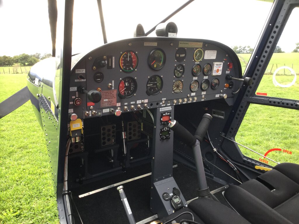
 Hi Mark. The AoA gauge is a Bendix King KLR 10.
 -
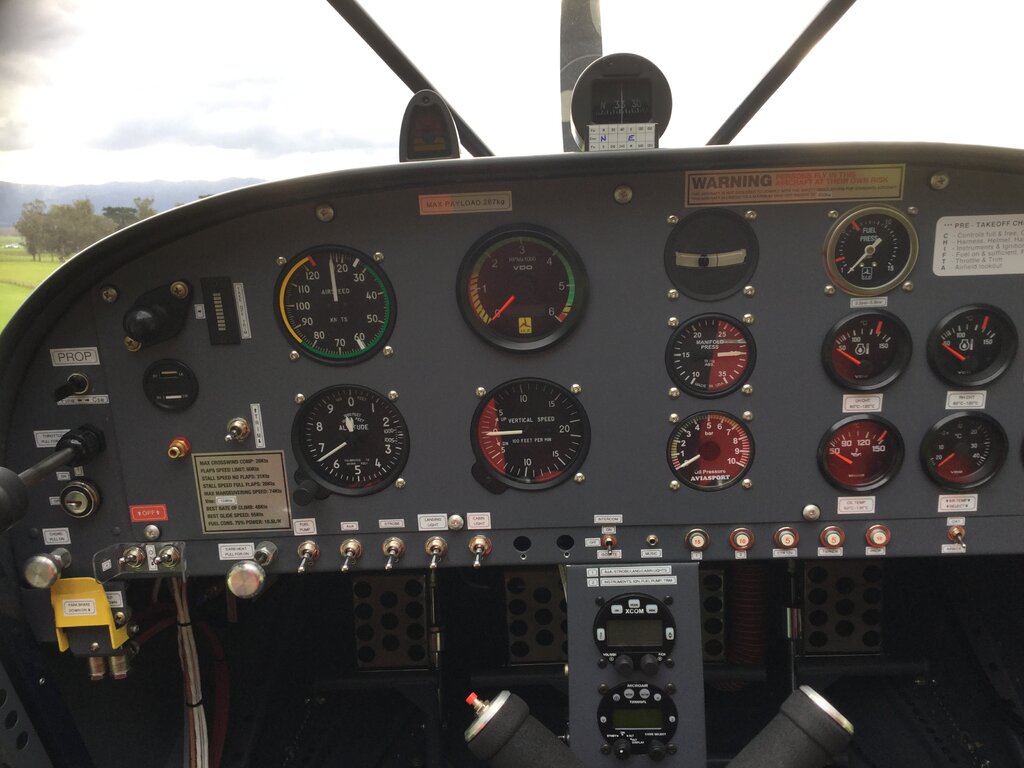
Here’s my Savannah S panel. The instruments I tend to focus on are the VSI (I find it great for fine tuning my hands off trim flight), and the AoA (Angle of Attack/lift reserve) The AoA gauge sits in my peripheral vision and is absolutely amazing. It takes into account the total aircraft weight in determining how close to the stall speed I am at. (There can be considerable difference in the stalling speed between that of a lightly loaded aircraft, and one that is flying at its MTOW) For a STOL type aircraft, it provides peace of mind when flying very slowly and also talks to me through my headset when close to the stall, all without needing to look at the ASI, therefore allowing me to keep my eyes focussed outside the cockpit on landing and takeoff.

-
What about this one. Clue: it’s not international.
-
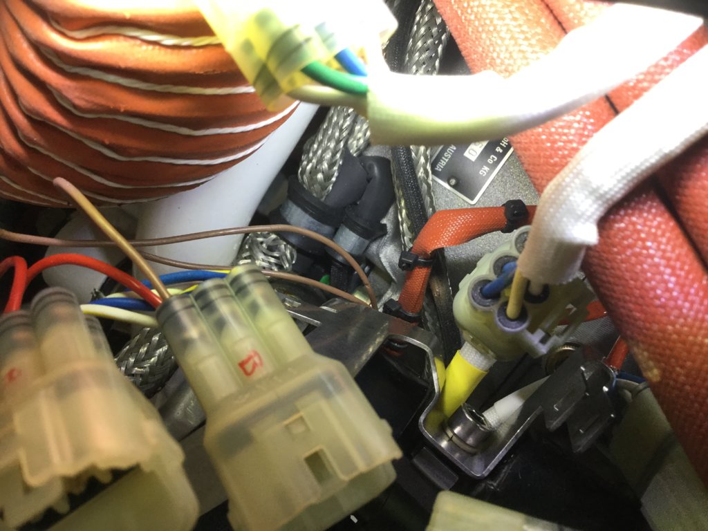
I had a no-charge problem on two different aircraft. (both Rotax 912) In the first instance I found that the two yellow wires on the connector that plugs into the regulator/rectifier (wires labelled “G”) had backed out of the plug slightly, to the point where the spade connectors on those two wires were not actually connecting. After discovering that, and then pushing the spade connectors in, problem fixed. The second time time was on my latest build. In that instance, I found that the recommended mounting of the regulator/rectifier was not giving a good earth. The fix was to make up a separate earthing wire connected to a good earthing point and bingo. Two simple checks before you dig too deeply. Cheers. Perry
-
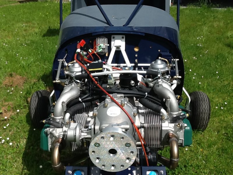
Hi Friarpuk. I had on-going ignition problems with my 912 after about 20hrs from new. When carrying out the pre take-off ignition checks, I would regularly experience RPM drops of 400 to 1000RPM, even to the point that the engine would basically quit but then spring back to life again. I tested and suspected lots of things. Checked earth connections. Changed all of the spark plugs etc etc. Eventually, in order to isolate a CDI unit failure/problem, I swapped the CDI unit (6 pin) plugs around. (The ones that come out of each CDI) This immediately fixed the problem, but I didn’t know why. (proved it wasn’t a CDI fault anyhow) Alas, after probably another 20hrs the problem reoccurred. Long story short, after pulling most of my hair out, and thinking life without an aeroplane would be much simpler, I stumbled on THE fault. One of the two brown wires (that go to the ignition switches) had been fretting itself on the bracket that holds the CDI units. When I swapped the 6 pin plugs over, it had temporarily re-routed the wire so it sat off that bracket, and the engine ran perfectly for a while. I could see an area of slight discolouration on the suspect wire, and double checked my suspicion with a multi meter. Sure enough, there was bare wire earthing itself onto the bracket. Effectively, each time the wire touched the bracket due to vibration, it had the same effect as switching off one of the ignitions. Anyway Friarpuk, it may not be your engine’s problem, but it’s worth a look. Here’s a pic. If you follow the brown wire down and enlarge the pic, you can see the fretted area. Cheers. Perry
-
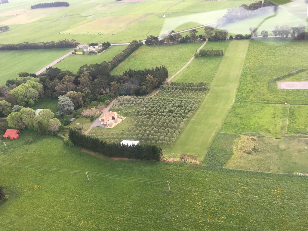
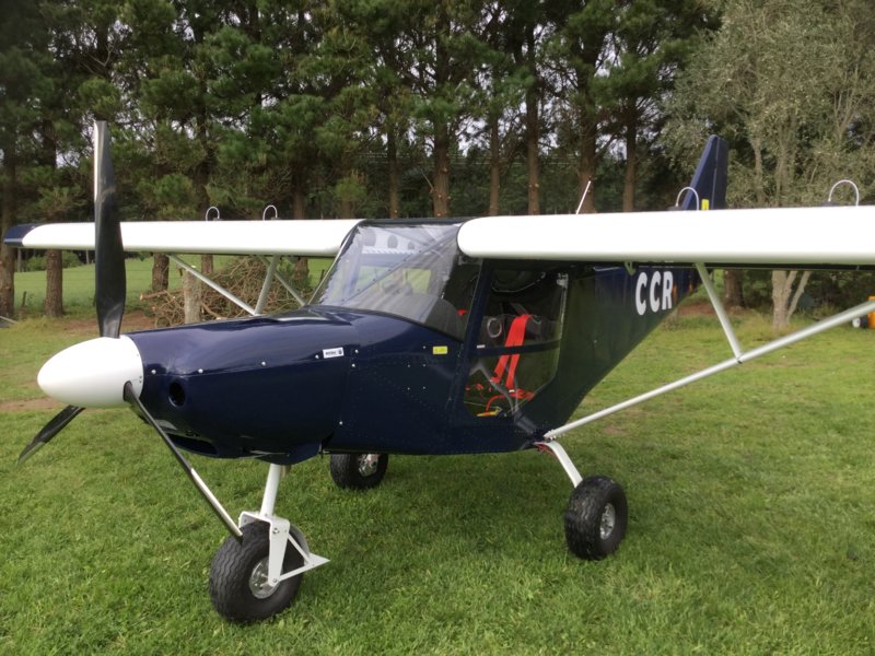
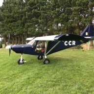
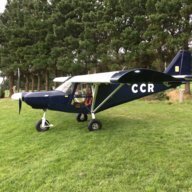
Landing my Savannah S at our strip in Wairarapa, NZ. Janine on camera duty. The aircraft has 72hrs flown so far since July last year.
-
Here’s a pic.
-
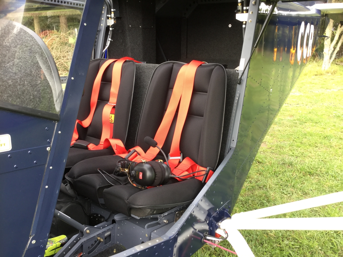
Hi Rodr. I have the adjustable seats in my plane and can say that they are bloody marvellous. There's four separate positions, with a total of four inches of travel. (100mm) Very easy to adjust, although this cannot be done in-flight. Only on the ground. As far as building them goes, the seats were probably the most enjoyable components to construct. All pre-drilled and the holes aligned absolutely spot on, which is amazing considering the final shape. Height wise, I'm almost six feet tall and there is plenty of head room, and that includes me having a 50mm thick foam pad fitted under the ICP supplied upholstery. (The supplied upholstery is very thin and uncomfortable when used by itself) I fly with the seat in the aft most position, and my (long) legs are almost straight. My partner is a shorty at 5'2", and she can "just" touch the pedals when the seat is in it's forward most position. She could probably do with a back cushion if she actually needed to fly the aircraft. Another point to note is that as the seats are moved forward, they actually rise up by probably an inch. (25mm) Cheers. Perry
-
Well done Bob. I'll have to pop up for a look at some stage, rather than just flying over your house! Perry
-
Here's the first flight.
-
Eightyknots. I hope you have some Devine intervention, or are ageless. If your current building rate of two hours every 3 months continues, your build will take 192.5 years! LOL. Perry.
-
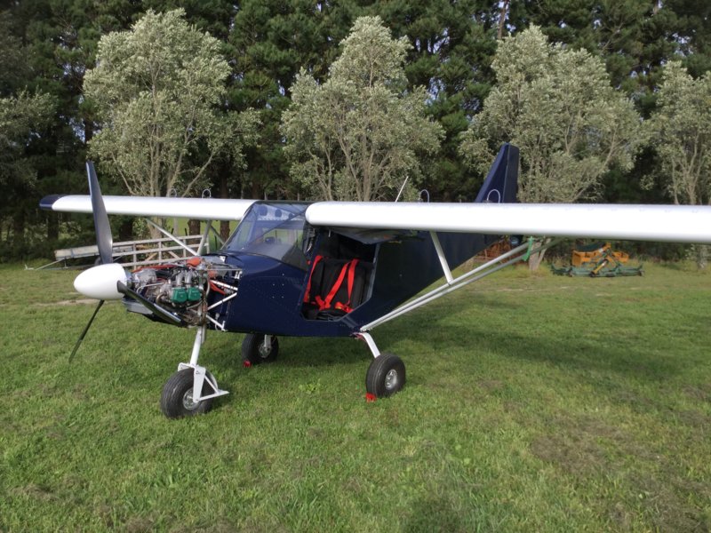
Hey MT. Do you sleep at night, or just keep building your aircraft? I can't believe how quickly you have got to this stage. Well done. Here's a pic of mine. First engine runs last Friday. I've spent 1540 hours building mine to date, and yet to paint the cowlings, and make some better seat cushions, as the factory supplied ones aren't comfortable. We may be in the air around the same time.
-
Hey Bob. My screen doesn't touch the upper diagonals. It's riveted with 6 or 8 rivets on the bottom half only. (ie: below the bend) Perry
-
That pilot is a crazy bathtard.
-
Hi Mark. I'm between Featherston and Martinborough. Nearly finished my build. Pete flies in here occasionally too when he's not working. We have accomodation if you wish. My mobile number: +64 211845791. Cheers. Perry
-
Hey Mark, are you still coming over to NZ Feb?
-
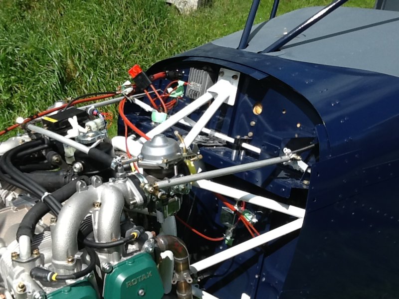
Hi Eric. I'm building a Savannah S. I didn't really like the cable set up either. It would probably work better if the cables were attached one on the LH side, and the other on the RH side, which is quite doable, but I really like the push/pull rod arrangement. It remains to be seen if there is enough engine movement to inadvertently affect the throttle operation, but by all accounts, with the "ring engine mount" system, it works well. Just last week I finished making the throttle set up using push/pull rods. As far as the hardware part numbers goes, I used what Rick posted regarding the rod-end bearings. (There's a RH threaded one and a LH threaded one for each push rod, which enables very accurate adjustment) Having access to a lathe is very helpful. You also need to purchase a LH thread tap. I purchased all of the hardware, including the LH tap, from Aircraft Spruce in USA. In addition to the rod-end bearings, you will need four "check nuts", that lock the bearings in place. (2x RH, 2x LH) For my rods, I used aluminium tube 0.500" x 0.058" 6061-T6, and turned up on the lathe the threaded inserts for the bearings to screw into. The inserts are held in place with rivets. I fitted my rods to the outside of the "fingers". It would be better to fit them to the inside though. To do this on the RH side is easy. In order to do this on the LH side requires removal of the throttle cable bracket. I didn't wish to do this just in case I need to revert back to the original cable throttle arrangement. Here's a couple of pics of my set up. I am very happy with the finished product, BUT PLEASE NOTE, I have just posted this to show what I have done. It is intended for information only. If you don't have the technical know how and access to machinery, then you are better off to stick with ICP's cable system.
-
The gap looks about normal. I did away with the "patch" piece that (in your photo) is clecoed behind the cabin frame. Instead I made a "patch/cover" that neatly fitted over the gap forward of the cabin frame. The windscreen rubber seal then tidily sits on top of that.
-
Hey MT. Before you "match" drill the two holes in the front of the cabin frame (the steel structure) through the firewall, you must FIRST fit the cabin frame very accurately. You will need the instrument panel pinned in place, but not necessarily the upper skin. The cabin frame is fitted using the supplied jigs that position the forward wing mount. Those two fwd holes will be the final task in fitting this structure, using the engine mount as a guide, as Kyle Communications mentioned. As a precautionary note, my manual (and probably yours too) states that there is a 5mm tolerance in the diagonal measurement when setting up the cabin frame. That tolerance seems awfully large to me. There is a possibility that the measurement should read 0.5mm. Either way though, the more accurate you drill that diagonal measurement into the frame, the straighter the wings will be when attached to your fuselage. Kyle Communications has some good pictures of how he measured the diagonal, by using nails accurately clamped to the fwd wing mount holes, which are used as a datum for sitting one end of your ruler of tape measure onto.
-
Hey MT. There's no stupid questions. I'm sure every builder has scratched their head trying to find info in the manual. Everything seems to be in there, just sometimes not in a logical place. I'm still working through it also.
-
Hi MT. You are allowed to look ahead in the construction manual so that you have an idea what you can rivet now, or wait. Also, the parts manual is very helpful to suss out how parts go together. I looked up the parts SF240/241. They hold the cowling in place, and attach on the OUTSIDE of the lower and upper skin. There is nothing that is sandwiched between the firewall and lower skin. Getting back to the firewall, I riveted pretty much all of the parts that attach onto it prior to fitting it. It is a lot easier to do that. Have a look at the parts that attach to the firewall also, so that they don't extend out from the edge. Some parts on mine needed a little trimming so they didn't touch the lower skin. With it on the bench you can also trial fit the NLG to make sure you get a good sliding fit of the leg. If you desperately want to rivet the firewall to the airframe at this time, I suggest you temporarily fit the upper skin and instrument panel, (instrument panel makes the correct shape) in order to find the correct position of the firewall. I say this because the firewall needs to pick up the holes in the upper skin. Just work through everything methodically. Sounds like you are doing fine. Cheers. Perry
-
It's probably easier to build the firewall up on the bench first. That way you will also have a bunch of cleco's spare. I found that some parts required a little trimming so that they don't interfere with other parts. For instance, you don't want the end of the angles (on the sides) to be tight into the radius of the firewall tabs. Just take your time and inspect as you go. As long as you don't trim too close to the rivet holes, you should be fine. General rule of thumb is to maintain 2.5 times the rivet hole diameter as the minimum edge distance.
-
Also I could not find parts SF 275 and 276 in the manual. MT: These two items don't seem to get much of a mention in the manual which is surprising, as they are a major structural part. From memory, you should see them in the parts book. They attach below and behind the rear panel of the cockpit, each side. They connect the meaty seatbelt angles to the fuselage sides.
-
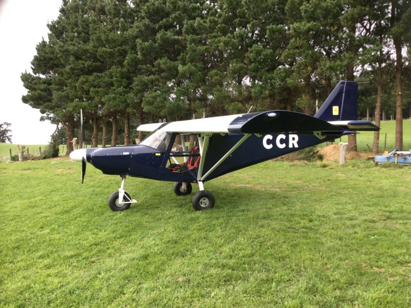
Gidday Hank. You are correct. Neither are steel blue. The colour scheme is what I am going for. Replace the dark colour with steel blue. I like the contrast with the white MLG/NLG etc. Have you ordered your kit yet?