Kyle Communications
-
Posts
6,669 -
Joined
-
Last visited
-
Days Won
100
Content Type
Profiles
Forums
Gallery
Downloads
Blogs
Events
Store
Aircraft
Resources
Tutorials
Articles
Classifieds
Movies
Books
Community Map
Quizzes
Videos Directory
Everything posted by Kyle Communications
-

Repacking a parachute(GRS)
Kyle Communications replied to Bluey's topic in Trikes and Microlight Aircraft Usergroup
My parachute came on a Emirates flight from Europe -
Repacking a parachute(GRS)
Kyle Communications replied to Bluey's topic in Trikes and Microlight Aircraft Usergroup
My parachute is a GRS The dangerous goods thing is pretty over the top. The rockets are anchored and you have to remove that anchor when it is installed. I imported mine directly from the factory but I piggybacked the freight with the BRS agent here. I also found out a few things about how this dangerous goods" thing is done and who does it. I found out by accident and now know who to approach directly for the dangerous good import details . These devices all come to Qld because it is who does the dangerous good import and paperwork and internal freight here in OZ. I have to get another parachute for my RANS S-21 but its a bigger one than the 600kg and is a lot more expensive but I will be chasing the freight for it directly with my now updated knowledge of how to do it. The 6 years repack and rocket changeout I was not going to worry about as I have done a bit of research into previous tests with older rockets and chutes and I have seen videos of rockets and chutes that are up to 15 and 20 years old and they were deployed to see if it was still viable and they all still worked. OH&S is a rippoff in most cases it redtape crap gone mad and not sensible as usual govt bullsh*t is. This makes things overcomplicated and of course expense comes with that when realistically it doesnt ahve to be. -
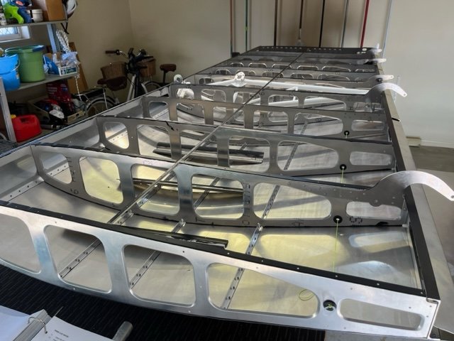
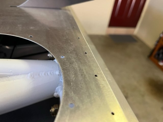
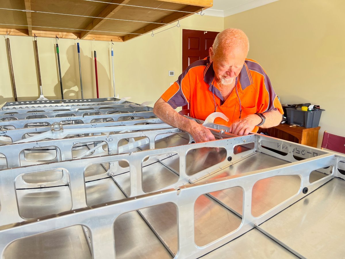
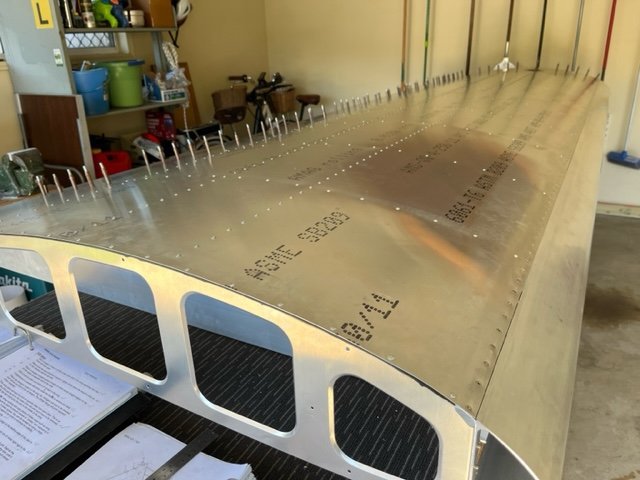
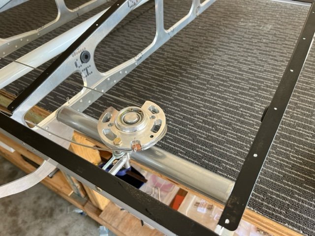
I have to confess its not all me doing this work on the RANS wings. I am not superhuman 😅 . I have great guy helping me get this done because I do have too many things happening at once here . I am very lucky to have him helping me get the wings done. Rodger wanted to have another project to do as he is retired and offered to give me a hand...of course I jumped at the offer. He has previously made a set of these same series wings for his aircraft, He is a master builder too. The previous aircraft a Waiex and RANS S-20 with the metal wing he has built are beautifully made. There is still a lot to do of course. The tail feathers and the fuselage will be delayed until I can get the new shed built here as all the other sheds have to be removed for the development of this block here at Burpengary. Mabel is almost ready to go to the hangar as soon as I can get the parachute install finished and that has to be done in the next week or three so the build shed can be cleared out to store all the stuff out of the first 2 of 6x9 sheds to be sorted and packed into boxes and stored in the 7x15 shed while the new 9 x 18 shed gets put up. Mabel will be moved to the hangar and the build table dismantled. Then all the gear will be stored in the 7x15 shed until the new one is up then the 7x15 will be taken away and the RANS will then be under way again in the new 9x18 shed...The house build at the farm should have its final inspection in about 2 weeks and the new shed up there hopefully will be erected in November, the concrete for the floor went down 2 weeks ago. That way all the farm gear will come out of the current hangar there and the hangar will be available for Mabel and the Mistress when she is finished.
-
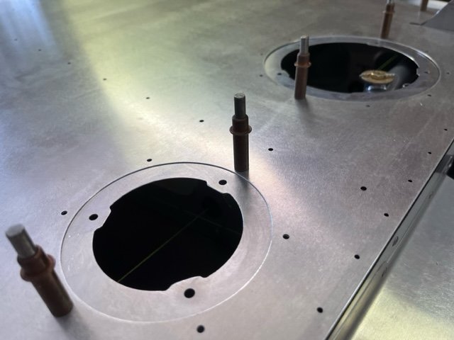
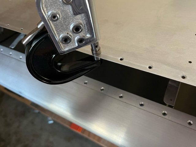
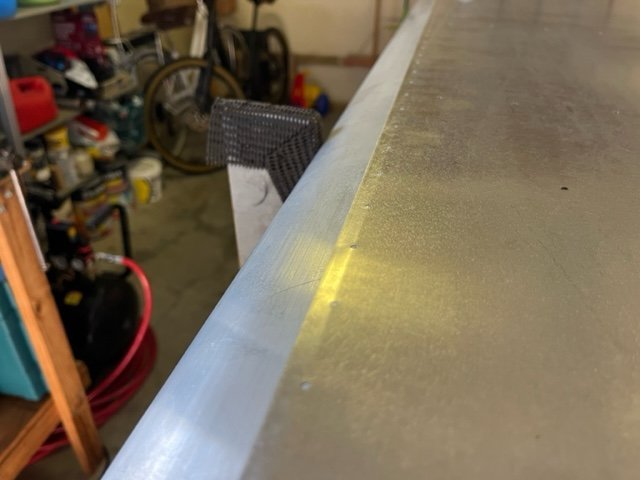
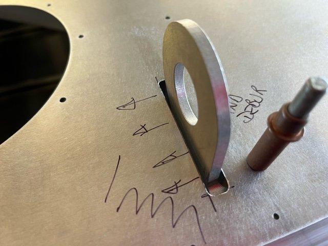
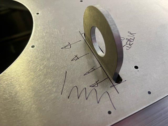
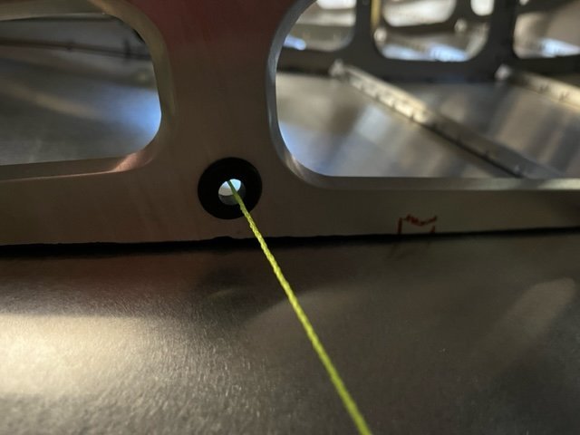
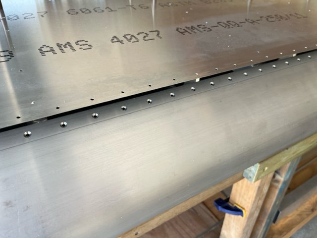
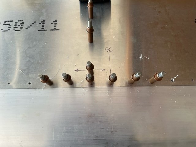
22-09-23 Removed bottom RH wing skin and vacuumed swarf from cavity. Roller applied two coats of anti corrosion paint to ribs, stringers, spars and fuel tank supports. Deburred access cover ring tabs and clecoed in position on skin. Squared and leveled wing structure and refitted skin. 2.1h

-
E-Props ...who has first hand experience with these
Kyle Communications replied to eightyknots's topic in Engines and Props
EXC-3-185-C4-T (X-AIR Rotax 582 gear ratio 2.62) This is what you would require for your Xair -
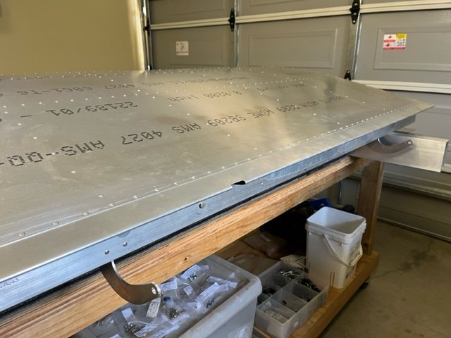
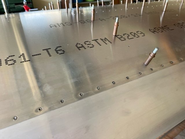
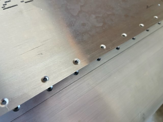
19/09/23 Match drilled leading edge of RH bottom wing skin to main spar. Removed clecoes and deburred bottom skin. Microstop countersunk main spar. Dimpled lead edge skin and re-clecoed skin to spar and ribs. 2.7h
-
E-Props ...who has first hand experience with these
Kyle Communications replied to eightyknots's topic in Engines and Props
Read the instructions for Eprop..they are the designers and manufacturers..they say pitch for 5500 WOT in level flight. This is where the prop is most efficient Setting it anywhere else you will obviously compromise the original design critieria. That drop off seems to be pretty large from my experience here with over 50 Eprop propellors fitted you must have a very high AOA on takeoff. most will climb at around 5200 to 5300 rpm when set to 5500 at WOT -
Marty I doubt that very much...still have a lot of work still to get done on Mabel and the S-21. The problem is there isnt enough hours in a day now I am retired..its worse than when I had a real job. Between trying to get the house at the farm to a final inspection and the concrete went down for a new tractor shed up there last week also subdividing this block we are on here at Burpengary not to mention trying to get CDI modules and throttle kits made, things here at Burps will come to a grinding halt soon as I have 4 sheds to pull down and a new 9 x 18 mtr workshop shed to go up which will be the new build shed as well. The sheds have to go for the develoment of the block and a new shed put on a totally new alignment. I hope I live long enough to get it all done. 😩
-
peeing while on long flight
Kyle Communications replied to RFguy's topic in AUS/NZ General Discussion
Dont forget the women as well DHCare Portable Female Women Urinal Camping Travel Toilet Device 4PCS,Purple : Amazon.com.au: Health, Household & Personal Care WWW.AMAZON.COM.AU DHCare Portable Female Women Urinal Camping Travel Toilet Device 4PCS,Purple : Amazon.com.au: Health, Household & Personal Care
-
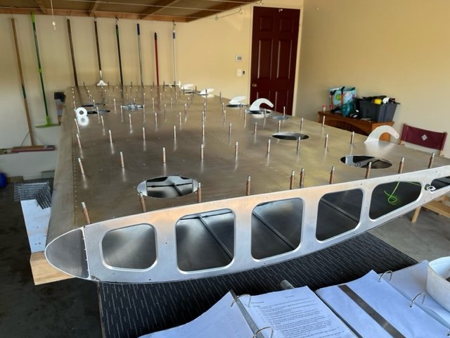
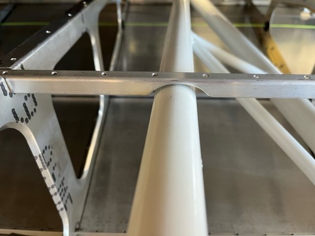
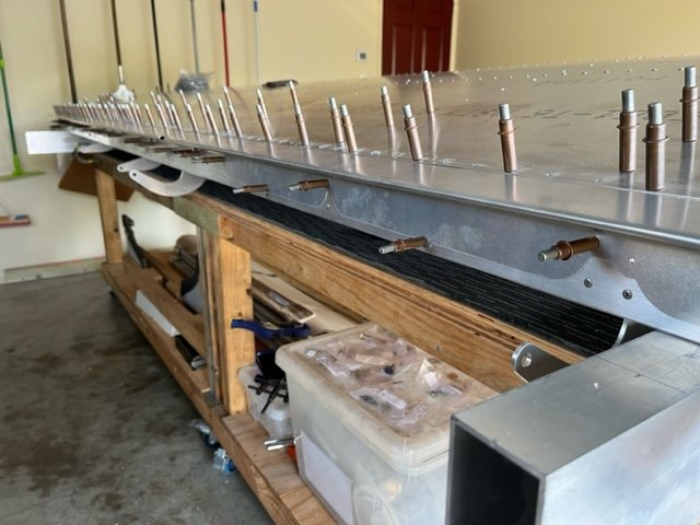
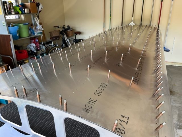
18/09/23 Inverted wing, leveled and squared structure on supports. Installed draw string for wing lights. Notched stringer around wing truss. Clecoed bottom skin to ribs to check aileron/flaps/tie down attachment penetration clearance. Removed skin and rolled edge break on leading and trailing edges. Trimmed skin around binding penetrations. Reinstalled and clecoed skin to ribs. 2.7h
-
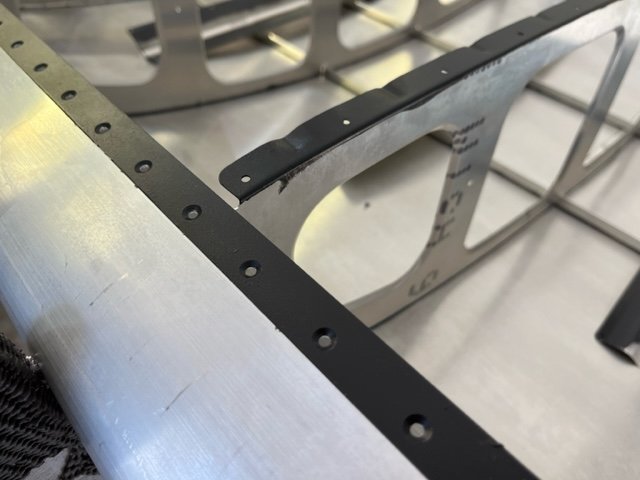
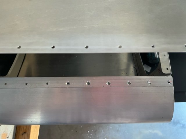
15/9/23 Match drilled rear spar to upper RH wing skin. Removed skin clecoes and deburred rear spar. Trimmed and deburred aileron and flap wing gap seals. Aligned gap seals with upper wing skin profile and clecoed into position. Match drilled gap seals to spar and removed to debur. Refitted gap seals and riveted remaining rows to wing ribs. Riveted gap seals to rear spar. 4.8h
-
New throttle system for Rotax
Kyle Communications replied to Kyle Communications's topic in Savannah
Oh yes she has many commands I must get done..she is still working so I am the gopher -
New throttle system for Rotax
Kyle Communications replied to Kyle Communications's topic in Savannah
Well I understand what you mean...been retired as such fr about 3 weeks and I need to go back to work for a rest -
New throttle system for Rotax
Kyle Communications replied to Kyle Communications's topic in Savannah
Savannah have a similar system on the firewall but use bowden cables one long and one short which of course creates issues with travel over each cable. Some have modified that to use 2 straight cables including myself. The rotating rod wears out over time. Most aircraft firewalls have other crap mounted on them. It was easier and more consistant to mount the whole assembly onto the carbs to tie them together and just use one throttle attachment. A couple of uys with savannah used my carb mount and use their bar on the firewall and use 2 rods with turnbuckles to operate my system. That seems to work fine as well so long as on a ring mount not a bed mount as the bed mount allows too much engine movement -
New throttle system for Rotax
Kyle Communications replied to Kyle Communications's topic in Savannah
I havent made any for a while as I have been so busy with other projects. I have another 10 almost ready except for the tig welding of the bars.Maybe in a couple of weeks I will have another batch done. I have just retired and am finding I still dont have enough hours in a day at the moent. But hopefully soon I can get a routine going building all this add on gear. -
Headset Jacks
Kyle Communications replied to skippydiesel's topic in Instruments, Radios and Electronics
The 3.5mm and 2.5mm plugs are used for handheld hadios -
Headset Jacks
Kyle Communications replied to skippydiesel's topic in Instruments, Radios and Electronics
I bought a set of Lightspeed Zulus. and have used them for about 10 years then Lightspeed offered a $450 upgrade to the the next version with the sexy kevlar cables and updated controller. Pacific Avionics did it and returned in less than a week. I have a set of DC,,,may as well be in the bin the Lightspeeds are light years ahead in comfort and performance -
Headset Jacks
Kyle Communications replied to skippydiesel's topic in Instruments, Radios and Electronics
Helicopters have a "Nato" plug ...seems to be a hold over from the military copters and never changed -
09/09/23 Riveted RH upper wing skin to ribs and stringers from leading edge back to five rows forward of rear spar. 3.7h
-
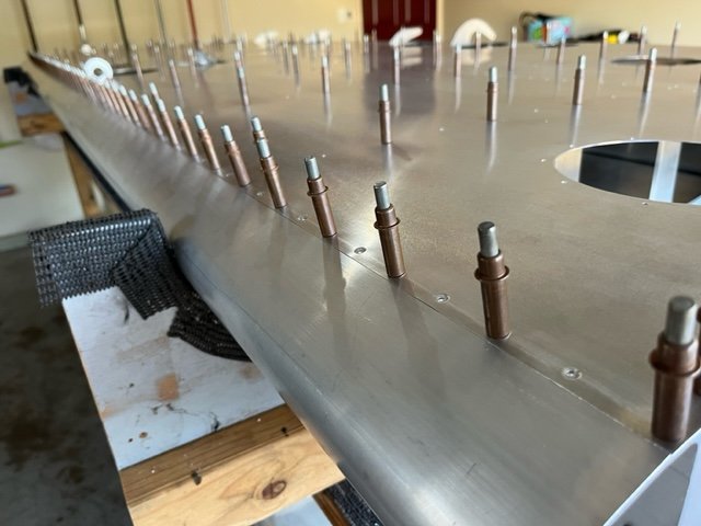
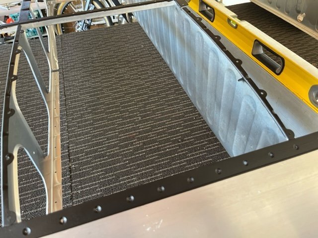
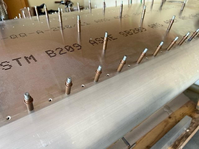
06/09/23 Checked adhesion of scupper plate to inner surface of RH upper wing skin. Safety wired aileron and flap bellcrank bolts to rib lightening hole flanges. Match drilled upper leading edge to forward spar and deburred. Microstop countersunk leading edge rivet holes. Dimpled RH upper wing skin leading edge rivet holes. Removed wing skin and roller applied two coats of anti-corrosion coating to ribs, forward and aft spars, stringers and fuel tank support contact surfaces. Reinstalled upper wing skin and levelled wing on supports. Riveted lead edge of upper RH wing skin to forward spar. 5.9h
-
No its not a red herring it is the start of the distaster..its the bit that triggered it. The pawnee may have called he was going to stop short but it looked like he was going to land a bit further than what he had planned. You MUST STOP at the crossover regardless It is in the ops manual and also just common sense. I have the benefit of seeing all the video and reviewing it many times as I had to recover it and send it to the coroners evidence folder and the ATSB.
-
When in doubt go around
-
No he didnt stop and just went straight across as the pawnee was touching down. The Pawnee would have expected him to stop so elected to do a go around after just touching down..which is what I would have done I think..as usually thats what I was taught .
-
Regardless of what runway was being used. Crossing 06/24 to get to 11/29 you are required to STOP before the crossover and look. Not necessary for any radio call of crossing but the requirement like any runway crossing anywhere is to STOP and look. The radio is a secondary input
-
I hve never heard of lapping lifters ever..only valves of course