bexrbetter Posted April 2, 2015 Share Posted April 2, 2015 I was surprised Rotec did not copy Jab heads, they have a collar on the guide so the guide can't come loose, Air-cooled engine concept, water cooled heads should never reach those temps, i.e. expansion, for guides to come loose. 1 Link to comment Share on other sites More sharing options...
AVOCET Posted April 2, 2015 Share Posted April 2, 2015 Sounds like a case of tradesman blaming their tools , when in fact , the poor old tool just carnt get it right ! Link to comment Share on other sites More sharing options...
hyundai Posted April 5, 2015 Share Posted April 5, 2015 CHT gauge how can I check if it reading right I put the end in boiling water it only showed 100 deg. Maybe it does not register in water the right way. I would think it would read 212 deg F. Link to comment Share on other sites More sharing options...
Guest Andys@coffs Posted April 5, 2015 Share Posted April 5, 2015 I presume the thermocouple is a K type, in which case the voltage it produces at ambient should be circa 1.2mV to 1.6mV (20C to 30C) at 100C it should produce 4.5mV These are very small voltages and you will likely need a DVM that has a thermocouple input (and usually comes with a thermocouple probe) Jaycar has these from about $40 and if you buy a cheapie and need a reference thermocouple, they are available (type K) with an appropriate plug for about $12.... I seem to recall mine cost about $60 and came with a thermocouple and did just about all electronic components measurements (V/R/L/C/Transistor Hfe and Temperature). As I said very small voltages so any dodgy connections will destroy the effect. Automotive spade connectors for crimping etc are imho crap and I personally prefer to solder, however understand that you are creating another junction in doing that (as you are with crimping) if the 2 materials being joined are not the same metallic content. there is plenty of guidance material on the net about extending thermocouples and what to do and what not to do..... I personally am not so interested in actual measurements, in flight, but rather am looking for changes in flight....I recall that the very original temp gauges that were fitted didn't even have markings for voltage/or temp other than something that said each increment on the gauge was X degrees...again your looking for delta's in flight, but you do need to know they are working accurately to start with, which is why a DVM with a reference thermocouple (known good) can be used to fault find, your engine thermocouple, or your dash meter, or any thermocouple extensions (avoid if at all possible) Andy Link to comment Share on other sites More sharing options...
bexrbetter Posted April 5, 2015 Share Posted April 5, 2015 CHT gauge how can I check if it reading right I put the end in boiling water it only showed 100 deg. Maybe it does not register in water the right way. I would think it would read 212 deg F. 100C = 212F. 1 1 1 Link to comment Share on other sites More sharing options...
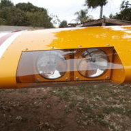
facthunter Posted April 5, 2015 Share Posted April 5, 2015 The LCH are cast. The others are machined from billett material. Castings if not elaborately done can be porous. This may/will cause leakage of oil and possible coolant displacement by combustion gases, dependent on where it occurs. Nev 2 Link to comment Share on other sites More sharing options...
gandalph Posted April 6, 2015 Share Posted April 6, 2015 Fo The LCH are cast. The others are machined from billett material. Castings if not elaborately done can be porous. This may/will cause leakage of oil and possible coolant displacement by combustion gases, dependent on where it occurs. Nev For example: Link to comment Share on other sites More sharing options...
hyundai Posted April 7, 2015 Share Posted April 7, 2015 Yes I believe Rotec have changed there way of making these LCHeads but that does not help me. If he would have done more stringent testing instead of just running the engine for a few hours. He should have come to the party and gave me 4 new heads?????. But at the end of the day I would not have anything from his shop on my aircraft. The later ones are not machined fron a billet like jab heads. Cheers Nev 1 Link to comment Share on other sites More sharing options...
Admin Posted April 7, 2015 Share Posted April 7, 2015 I personally wouldn't touch anything from that company 1 Link to comment Share on other sites More sharing options...
hyundai Posted April 7, 2015 Share Posted April 7, 2015 I personally wouldn't touch anything from that company Landing is mandatory ....... I like that quote, Link to comment Share on other sites More sharing options...
hyundai Posted April 7, 2015 Share Posted April 7, 2015 Landing is mandatory ....... I like that quote, I was thinking last night would it be great if CAMIT cam up with cross flow heads for jabiru engines that is intake On the top of the heads not from under as they are now. Would alimenate different cyl temps I am sure? I know Camit would be the company to make them. They would sell like hot cakes. Link to comment Share on other sites More sharing options...
facthunter Posted April 7, 2015 Share Posted April 7, 2015 The best place for the carburetter(s) is under the motor for safety reasons. With direct or port injection it wouldn't matter. The actual cross flow does not do much for heat variation, but designing more fins around the hot parts and flowing cooling air correctly, does. Most of the engines we are considering don't have extra cooling around the exhaust side of the heads and are symmetrical pretty much as far as ports are concerned. It would be practically impossible to billett machine an LCH as you can't do the water jackets without subsequent welding or an extra gasket, or join. Most aero air cooled engine cylinder heads are cast with some being forged. This is really high quality work with metal dies and vacuum casting techniques. High cost and prohibitive for low volume. You get what you pay for. Nev 1 Link to comment Share on other sites More sharing options...
fly_tornado Posted April 7, 2015 Share Posted April 7, 2015 If you want liquid cooled heads, why not buy a Rotax? bound to work out of the box, no problems, set and forget, turn the key and go. Link to comment Share on other sites More sharing options...
facthunter Posted April 7, 2015 Share Posted April 7, 2015 A correctly designed aircooled motor is satisfactory and simpler. No water pump, radiators hoses etc. There's no vehicle more suited to air cooling than an aeroplane. With liquid cooling there are advantages for things like glider towing, crop dusting and para drops. Nothing is absolute in all this. Nev 1 Link to comment Share on other sites More sharing options...
Ron5335 Posted April 7, 2015 Share Posted April 7, 2015 If it's 100 deg C , then it's spot on 2 Link to comment Share on other sites More sharing options...
gandalph Posted April 8, 2015 Share Posted April 8, 2015 If you want liquid cooled heads, why not buy a Rotax? bound to work out of the box, no problems, set and forget, turn the key and go. Well there's always the problem of engineering approval, fitting, plumbing, weight & balance...... Link to comment Share on other sites More sharing options...
jetjr Posted April 8, 2015 Share Posted April 8, 2015 Lack of power for many, absurd cost, expensive parts........... 1 Link to comment Share on other sites More sharing options...
Old Koreelah Posted April 8, 2015 Share Posted April 8, 2015 ...and that horrible clunk when they shut down. 1 Link to comment Share on other sites More sharing options...
SDQDI Posted April 8, 2015 Share Posted April 8, 2015 ...and that horrible clunk when they shut down. But it does seem to be mainly when I turn the key off:surrender: Lol couldn't help myself OK:victory: 3 3 Link to comment Share on other sites More sharing options...
Guest Andys@coffs Posted April 8, 2015 Share Posted April 8, 2015 Well there's always the problem of engineering approval, fitting, plumbing, weight & balance...... And assuming you need all of those with the rotax then which of those can be avoided with the alternate? Link to comment Share on other sites More sharing options...
gandalph Posted April 8, 2015 Share Posted April 8, 2015 And assuming you need all of those with the rotax then which of those can be avoided with the alternate? Well , if I changed the word "fitting" to " fettling" I would suggest almost all of them could be avoided. The original post in this thread referred to a problem fitting LC heads to a Jabiru engine and FT asked why not fit Rotax, I Would suggest that replacing a jab engine with a jab engine (like for like) would need none of those steps I mentioned apart from , obviously, fitting the thing. As a cautious person, I would check that the plumbing for air, fuel and exhaust remained suitable and the w&b remained as before and complete all necessary paperwork. Link to comment Share on other sites More sharing options...
Guest Andys@coffs Posted April 8, 2015 Share Posted April 8, 2015 Which was what I was getting at, LCH or rotax, both are not minor and imho all those things are really needed for both. I do accept that the engineering analysis needed for the rotax is more substantial, but the LCH isn't imho plug and play. Link to comment Share on other sites More sharing options...
gandalph Posted April 8, 2015 Share Posted April 8, 2015 Which was what I was getting at, LCH or rotax, both are not minor and imho all those things are really needed for both. I do accept that the engineering analysis needed for the rotax is more substantial, but the LCH isn't imho plug and play. Ah. Sorry, I misread your meaning of alternate. I thought you meant it in the wider sense of an alt engine. My oops. Link to comment Share on other sites More sharing options...
Kai Lyche Posted April 8, 2015 Share Posted April 8, 2015 I for one am one happy user of the LCH´s on my (previous broad finned head) mech lifter 2200A. From the production # it is evident that my heads were manufactured sometime in late 2013. I was forced to make a choice between new aircooled narrow finned Jab heads and LCH when I due to plain ignorance overheated my two rear heads during ground running and they went "plastic". Pricewise the LCH conversion kit from Rotec won hands down, as it turned out I would have to substitute my heads with the newer narrow finned ones. Another reason for making this swap was an intense desire to reduce the possibility of detonation. A "happy user" does not imply that everything was initially plain sailing with these heads. I went through the first ordeal when I test pressurized the cooling system: the connector banjo´s on top of the heads refused to seal properly. I am embarrassed to admit that it took a while before I discovered that I had installed the banjos upside down :-( Things perked up after this! Still with comparatively few hours on the LCHs (apprx 50), mainly due to dismal winter weather (I HATE those stories of beautidul flying weather that always seems to prevail both Down Under and in the US), the next issue was lubeoil leakage due to worn o-rings on the rocker shafts. It turns out that center groove for the 1/4" capscrew intended to lock the rocker shafts in place, is too deep: the shafts were oscillating along with the rockers and could not be kept still. Substituting the capscrews with others having an unthreaded part, solved this- but not the entire oil leak: the orings still wear out or flatten or soften up, or whatever. Presently the leak is just annoying and I have a program going trying to introduce some super sealant as well in the oring grooves. If that does not help I will substitute the shafts with 12mm diam close tolerance bolts, using bolt head and nut as a positive sealing surface. BUT the heads are cooling as advertized. Very seldom I have as much as 90C on the cooling liquid and 120C on the cht. A far cry indeed from the previous 170C on the aircooled heads. 3 Link to comment Share on other sites More sharing options...
Ron5335 Posted April 8, 2015 Share Posted April 8, 2015 Which was what I was getting at, LCH or rotax, both are not minor and imho all those things are really needed for both. I do accept that the engineering analysis needed for the rotax is more substantial, but the LCH isn't imho plug and play. Definitely not plug and play, and probably not as simple as it sounds, as the radiator and pump are below the engine, so any air in the system will congregate up high in the furthermost cavity away from the pump (A Head) but every time you take the filler cap off, it will be full and you can run the pump all day and it will stay there. This is overcome by inserting a header tank at the end of the circuit (Where the coolant goes from being pushed to being pulled) and as the coolant flow slows due to the size of tank, any trapped air will be released and simply stay at the top of the tank (That also doubles as the filler point). If your using a cross flow radiator, don't forget to TIG in a 5mm nipple on the top of the side tank, that you use as a bleed point to ensure the radiator is full of coolant and not air. No mention about that in the instructions, then again...... What instructions? "It's a long climb to get to the top, but the top but once there it's worth it" 1 Link to comment Share on other sites More sharing options...
Recommended Posts
Create an account or sign in to comment
You need to be a member in order to leave a comment
Create an account
Sign up for a new account in our community. It's easy!
Register a new accountSign in
Already have an account? Sign in here.
Sign In Now