facthunter Posted July 27, 2015 Share Posted July 27, 2015 You seem to be keeping away from idle boredom. Nev 1 Link to comment Share on other sites More sharing options...
Oscar Posted July 28, 2015 Share Posted July 28, 2015 HITC, that's really impressive. Your welding is something I admire; having built several race-car tube frame chassis and a number of aircraft-related bits and pieces, the skill required to get a complex set of tubes all welded up without them pulling everything out of feck is not a skill most people will truly appreciate. You - very obviously to me - understand that it's not just fitting but also weld sequence in a multi-tube frame that makes the difference between something that comes out to spec. and something that ends up just not to dimension. Been there... I notice that you intend to incorporate the 'Dafydd Llewellyn' vg ideas in your design. May I - respectfully - suggest that you get in touch with him and discuss the intricacies of those? He lives not all that far away from you. About six months ago, I believe, the chief Test Pilot from the FAA Small Aircraft Directorate flew the Sunbird Seeker, and commented that the stall characteristics were amongst the best he has ever flown. He added that he will be recommending to the FAA Small Aircraft Directorate, that they contact Dafydd Llewellyn to (this is not a verbatim quote) 'seek his assistance to understand how the aerodynamic design works'. Subtext: the application of the vgs to the Sunbird Seeker is sufficiently subtle in design that it's NOT intuitive nor something that one can say: 'oh, I see how that works, no worries'. Sub-subtext: 'none of you smart@rse engineers in the Directorate have the brains to understand how this works'. The Seeker vg installation took many, many months of trial, test flying and changes, to get it right. With the greatest respect to companies such as Stolspeed - who have done great work and provided excellent information for those looking to use vg's to improve their aircraft's flight characteristics - there is NO 'one size fits all' answer - you cannot JUST apply a handful of vg's to your aircraft and it becomes magically transformed. A familiar analogy would be the time in the 70's when 'lowering and wide wheels' was considered to be the 'magical' answer to an ill-handling motor vehicle. Sometimes it worked, other times it made a dog into a vicious dog. Your project is fascinating; there is very obviously a great deal of experience, thought and plain hard yakka involved. It will be extremely interesting to see how it all progresses. 2 2 Link to comment Share on other sites More sharing options...
Head in the clouds Posted July 28, 2015 Author Share Posted July 28, 2015 Thanks Oscar, kind words indeed. Yes, welding sequence is critical and before that, the sequence of the tacking. Since it's very difficult (read impossible) to keep the frame clamped flat to the bench during the welding out (because you can't get all around the joint without re-positioning the frame frequently) it's important that the tacks hold it mostly flat as the welds are completed, and keeping a weather ear out for the 'ting' of a stressed tack letting go and re-tacking it as necessary. You're right, I should have a chat with Dafydd, he's a very learned and helpful man, if a little taciturn on occasion when dealing with we 'unqualified non-engineers'. Nonetheless he was very helpful in revealing the intricacies of his Airflow Kit mods in the "Do vortex generators really work" thread. Actually, I'm not particularly a fan of VGs and don't have any plan to use them initially, if at all*. I mentioned that I would be incorporating some of Dafydd's methodology and that part is the inboard features, the stall strip and wing fences to act as a power-off stall-limiting device and the consequential vortices that keep the yaw under control. Outboard Dafydd's method uses a drooped leading edge with VGs whereas I will have fixed slots instead. (* - One objection I have to VGs is how much harder it is to clean that part of the wing, and the consequent corrosion that could develop around each of them. I may, however give in and use them but only directly in front of the ailerons where they may help to ensure that part of the wing is the very last to stall, especially if they can be shown to keep that part unstalled even if full aileron is employed when the rest of the wing is stalled. That would ensure that wing-drop will not occur at any stage of a (progressive) stall, and permit use of aileron (though I don't approve personally, I use rudder) to keep the wings level in the stall - all part of fool-proofing the design as much as possible). The fixed slots will give me flow attachment to a higher alpha than VGs ever could and provide a CL Max of around 1.75 (and over 2.1 with slotted flaps deployed as well), also way higher than VGs alone can offer. Using the slot shape described in NACA Report 407 (Weick & Wenzinger) I can avoid the complications of a movable Handley Page style of slat and still have minimal extra drag in the cruise. The only drawback being the extra limitation on Va due to the high CL Max that might be achieved when encountering gusts. That simply means a combination of slightly beefier spars and a lower Va imposed when flying light. ( Those who don't know about Va could read the Manoeuvring speed thread, one explanation is in post #34). Link to comment Share on other sites More sharing options...
Oscar Posted July 28, 2015 Share Posted July 28, 2015 Ah yes, that 'ting' noise..... I know it well. Got the sequence wrong on one chassis and after three goes, decided to plate the corner - it was that or dismantle too many tubes and start again. Using too many vg's in front of the ailerons is tricky; it can introduce a final and very, very sharp breakaway stall of the aileron which can make the stall very 'interesting'.. The inner vg's on the Seeker are designed to influence the downwash on the tailplane so that it it actually limits the maximum amount of elevator power so you can't drive the thing into a severe stall - but to the point where the thing settles into a mush with the centre section benignly stalled, keeping the ailerons fully effective. I know that it's tricky to get right; at one stage they re-painted the wings on the test mule and suddenly it wasn't flying quite right - because ONE of the centre vg's had been put back out of place, by not much either! Re corrosion - I like the Stolspeed vg's, they look pretty good and won't cause a problem ( well, I can't see how they could!). Moving slats... I'd not go there, I agree, unless there is some really compelling reason to do so. Flew in something - I am having a mental block re the name - low wing, French design - that had them from Canberra-Tocumwal and return once; it climbed like crazy but at cruise, the combination of the slats and a bit too much dihderal had it weaving in every gust like a Sunday-morning drunk on his way home from the pub.. Now, the set-up on the Wittman Buttercup, I think is rather clever, though a danger when doing the D.I. Will be fascinated to watch your progress; it should be quite a machine when it's finished. I suspect Dafydd Llewellyn would be most interested to chat with you - he appreciates people who THINK about things rather than just draw a shape because they think it 'looks right'. Cheers! 2 Link to comment Share on other sites More sharing options...
ave8rr Posted July 28, 2015 Share Posted July 28, 2015 Moving slats... I'd not go there, I agree, unless there is some really compelling reason to do so. Flew in something - I am having a mental block re the name - low wing, French design - that had them from Canberra-Tocumwal and return once; it climbed like crazy but at cruise, the combination of the slats and a bit too much dihderal had it weaving in every gust like a Sunday-morning drunk on his way home from the pub Oscar - were you thinking of the Socata Rallye MS880B? From my memory, they flew a bit like as you described above. Mike 1 Link to comment Share on other sites More sharing options...
Oscar Posted July 29, 2015 Share Posted July 29, 2015 YEP - that's the one. I've had more comfortable trips in a fat-bottomed yacht in a 3/4 following sea.. 1 Link to comment Share on other sites More sharing options...
David Isaac Posted July 29, 2015 Share Posted July 29, 2015 Morane Saulnier Rallye Type MS880B STOL actually, made by Socata, I did my first solo in one in 1970 at 16 years of age. Great thread Alan, thanks for your info; eagerly watching. 1 Link to comment Share on other sites More sharing options...
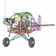
Head in the clouds Posted July 29, 2015 Author Share Posted July 29, 2015 Last Monday/Tuesday I completed the welding of the second fuselage side and really enjoyed doing it. The welds are getting neater and brighter as I get more practiced again. Once I had the sides done I had to go back to the early part of the next stage so it was all a bit deja vu. Back to the CAD work and produce a dimensioned set-out for the aft fuselage sides, produce full-size templates of all the member junctions, transfer the full-size set-out to the project bench, attach the cluster templates ready for fitting the wood blocking that will hold the tubes in position, produce the CAD wrap templates for the tube member ends, cut the tube members to length and de-scale them in the lathe ready for painting. Then I cut the wood strips up for the blocking. I did have an interesting moment while de-scaling the lengthy longeron members. Necessarily I had a long overhang at both ends and they decided to resonate and had the lathe jumping around the shop floor so I hung a bit of rope over each end with a couple of pounds of lead attached to act as a damper, worked a treat. A bit of graphite dust where the rope was rubbing made sure it didn't get hot from friction and catch alight ... Pics show welds still getting better and the preparation for the aft fuselage sides - 2 Link to comment Share on other sites More sharing options...
Oscar Posted July 29, 2015 Share Posted July 29, 2015 Jeez, that is NICE welding! You wouldn't get a raised eyebrow, I reckon, if you said it had come out of Barry Manktelow's shop - and Barry is an artist with a tig torch. Well. maybe from Barry himself, but few others would know. Thanks for the heads-up on the 2% Lanthanated tungsten electrodes; I've always used thoriated on steel and was completely unaware of the health aspects. I'll be changing.. haven't done a lot of tig stuff recently ( like, last ten years!) and am a bit rusty; my last job of late was an engine mount for an engine test cell, and though I claim 'extenuating circumstances' because it was done outside and freehand, your welding leaves me mighty jealous. About the only thing good about it, is that a Jab engine plugs straight on, so I got the welds to not pull things out of line. Incidentally - if you are ever looking for a tube notcher (and your stuff says you don't need one..), I bought a JD2 Notchmaster ( https://www.jd2.com/p-63-notchmaster.aspx ) a few years ago, after many years of notching by hand - and it is a REALLY good tool. They are gaggingly expensive by comparison with the el-cheapo pressed-steel ones, but are as solid as a cyclone-rated brick outhouse and correspondingly accurate.. You need to put a chamfer on the cut edge to ensure proper penetration throughout the joins, but with a thin s/s cutting wheel used carefully, ( yes, they should NOT be used for grinding, but hey, they do the job and don't leave bits of carborundum in the join face) the joins come up just a treat. 2 Link to comment Share on other sites More sharing options...
Head in the clouds Posted July 29, 2015 Author Share Posted July 29, 2015 Slow 'real work' days on Monday and Tuesday gave me time to cut, drill and screw the woodblocks onto the table, positioned along the lines on the paper templates. Then marked and bent the longerons by heating with a propane torch. And used the wrap templates and spray-paint to mark all the tube ends ready for notching - Total hours on the project to this stage is 185hrs 1 Link to comment Share on other sites More sharing options...
Marty_d Posted July 30, 2015 Share Posted July 30, 2015 HITC, I'm amazed at how quickly you're getting this design from concept to physical. Added to which, while I know nothing about welding, those who obviously do are impressed by the level of craftsmanship you're displaying. Thanks for sharing this with us, it's inspiring stuff! 1 3 Link to comment Share on other sites More sharing options...
Guest SrPilot Posted July 30, 2015 Share Posted July 30, 2015 Thanks Hitc for describing your project. Everything I've seen so far appears superb. I built one kitplane and finished another one so I can appreciate to some extent what you're experiencing. Not all though - I built from kits; I didn't design anything (other that small parts such as fairings), and I never learned to weld. No need on my projects. But I am an admirer of craftsmanship and your welding looks great. I also echo Marty_d's amazement at how far you've gone in such a short period of time. I spent 6 1/2 years building a "200 hour" kitplane! (More like 2500 hours, I think). The discussion of your thought processes is as interesting as your description of your work. I find it just as fascinating to read why you are doing things as it is to read about what you are doing. Thanks for sharing all of it. Joe Link to comment Share on other sites More sharing options...
Kyle Communications Posted July 30, 2015 Share Posted July 30, 2015 So after this weekend I will expect we will see the sides of the fuselage done. Allan certainly isnt mucking around Mark 1 Link to comment Share on other sites More sharing options...
Kyle Communications Posted July 30, 2015 Share Posted July 30, 2015 That notcher is really nice. It would be a tool you would have to buy doing the amount of tube work done on this thread The freight would be dearer than the unit 1 Link to comment Share on other sites More sharing options...
Oscar Posted July 30, 2015 Share Posted July 30, 2015 Ha! I bought it direct from the factory and the airfreight to Australia was something like $100 or so - then - because I had STUPIDLY not elected to have it posted to my local P.O. but instead elected to collect it from a freight store in Sydney... Sydney airport charged me $90 to get it off the plane. Any parcel, they charged for at pallet rate. The airfreight company charged me something like $160 to move it less than 1 km to their premises, and Customs charges caused it all to cost me $340 or so before I could get my hands on it. It is lucky that Sydney is still standing, I went thermonuclear. However, it IS really good; I had a specific project for it, which unfortunately changed direction, but every time I've used it - e.g. that engine mount - I've not regretted spending the money on it. Link to comment Share on other sites More sharing options...
facthunter Posted July 30, 2015 Share Posted July 30, 2015 Pilots are cool Oscar Remember that. Nev Link to comment Share on other sites More sharing options...
Oscar Posted July 30, 2015 Share Posted July 30, 2015 Damn near melted the headlining off the car after I'd paid the bill.... but the actual JD2 people were great to deal with, and everything up to it arriving in Sydney had been great, and very reasonable priced. Link to comment Share on other sites More sharing options...
Kyle Communications Posted July 30, 2015 Share Posted July 30, 2015 Ha! I bought it direct from the factory and the airfreight to Australia was something like $100 or so - then - because I had STUPIDLY not elected to have it posted to my local P.O. but instead elected to collect it from a freight store in Sydney...Sydney airport charged me $90 to get it off the plane. Any parcel, they charged for at pallet rate. The airfreight company charged me something like $160 to move it less than 1 km to their premises, and Customs charges caused it all to cost me $340 or so before I could get my hands on it. It is lucky that Sydney is still standing, I went thermonuclear. However, it IS really good; I had a specific project for it, which unfortunately changed direction, but every time I've used it - e.g. that engine mount - I've not regretted spending the money on it. I see they are available here in australia. All of the JD squared stuff...it in Sydney http://jd2.com.au/ $525 inc GST would probably cost that to get one here from the USA given the current exchange rate anyway Link to comment Share on other sites More sharing options...
Oscar Posted July 30, 2015 Share Posted July 30, 2015 I see they are available here in australia. All of the JD squared stuff...it in Sydneyhttp://jd2.com.au/ $525 inc GST would probably cost that to get one here from the USA given the current exchange rate anyway Yes, it cost me more than that. There was no agent in Aus. when I bought it about five years ago. The only local alternative then was a Hafco pressed-tin lousy device, and 4130 buggered-up isn't cheap. Link to comment Share on other sites More sharing options...
Head in the clouds Posted July 30, 2015 Author Share Posted July 30, 2015 Incidentally - if you are ever looking for a tube notcher (and your stuff says you don't need one..), I bought a JD2 Notchmaster ..... Looks like a good bit of gear Oscar. If I hadn't gone to the extent of producing the wrap templates I'd probably be taking you up on your kind offer but with the shape laid out in spray paint it just takes a couple of minutes to cope each tube end and a couple more to fit them up a bit better. In the longer term, if the aircraft lives up to expectation and I was ever to consider producing a kit then probably any manual method is just too tedious but I reckon the way to go would be to get the tubing notched like this - I hope so Mark. I should have both sides tacked together by the end of Saturday all things being equal but then there's a day or more to weld out each side and that part gets really tricky as the tubing gets smaller and thinner toward the tail. The rearmost pair of diagonals are only 1/4" (6.35mm) outside diameter and 0.035" (0.9mm) wall thickness, so it's easy to blow that thin stuff away altogether with too hot an arc, let alone just blowing holes in it ... can't afford to lose concentration for even a second on that stuff. 2 Link to comment Share on other sites More sharing options...
Kyle Communications Posted July 30, 2015 Share Posted July 30, 2015 Wow I love that laser cutter. For work we use a mob over the southside to get all of our metal work lasercut although its all flat plate stainless and aluminium and zincaneal. They are very progressive I wouldnt be surprised if they had a cutter like that and they are super cheap for what we get done. I might flash them a email and see if they have that capability or at least know who does. Link to comment Share on other sites More sharing options...
Kyle Communications Posted July 30, 2015 Share Posted July 30, 2015 Funny about the tig welding. Just saw this on a FB post thought I would put it up here. This is some special tig welding skills https://fbcdn-video-b-a.akamaihd.net/hvideo-ak-xtp1/v/t42.1790-2/11721705_954854061227322_1170893149_n.mp4?efg=eyJybHIiOjYyNCwicmxhIjo1MTJ9&rl=624&vabr=347&oh=19e5f90a3fbd0f084dcb141c43f45d95&oe=55BAC582&__gda__=1438304977_287d9d5ef6256ae9d71ec8cf96bb87f5 You can make the video bigger of course to get a better look Link to comment Share on other sites More sharing options...
fly_tornado Posted July 31, 2015 Share Posted July 31, 2015 these guys do the whole aircraft tubing kits, works out about US$2500-$3000 more expensive than just the material http://vr3.ca/refdocs.html have a look at the fuselage links at the bottom of the page, it has detailed part descriptions 1 Link to comment Share on other sites More sharing options...
Oscar Posted July 31, 2015 Share Posted July 31, 2015 Yep, they are well respected. However - and at the current exchange rate - there are several good CAD programs that will draw paper templates for each tube; slower but a lot cheaper! Link to comment Share on other sites More sharing options...
Kyle Communications Posted July 31, 2015 Share Posted July 31, 2015 https://fbcdn-video-b-a.akamaihd.net/hvideo-ak-xtp1/v/t42.1790-2/11721705_954854061227322_1170893149_n.mp4?efg=eyJybHIiOjYyNCwicmxhIjo1MTJ9&rl=624&vabr=347&oh=280f7c0284085068bc7b33220edd6492&oe=55BB2342&__gda__=1438331377_e387fc9283b40ed1795e5164c124b85d This link should work Link to comment Share on other sites More sharing options...
Recommended Posts
Create an account or sign in to comment
You need to be a member in order to leave a comment
Create an account
Sign up for a new account in our community. It's easy!
Register a new accountSign in
Already have an account? Sign in here.
Sign In Now