fly_tornado Posted January 27, 2016 Share Posted January 27, 2016 this is how titan do adjustable pedals, the adjuster is between the pilots knees on the floor Link to comment Share on other sites More sharing options...
Head in the clouds Posted January 27, 2016 Author Share Posted January 27, 2016 this is how titan do adjustable pedals, the adjuster is between the pilots knees on the floor[ATTACH=full]41005[/ATTACH] Yes, it's an example of one of the 'simple' ones I described in para 3 post #92, and only has nice pedal geometry if you're 5ft 9in - but if you're shorter or taller the pedals move up and down instead of just back and forth. It's also got another very questionable aspect because it relies on the nosewheel steering linkages to operate the rudder cables. So if you break, bend, disconnect or generally damage your nosewheel steering on takeoff you lose your rudder control as well. 1 Link to comment Share on other sites More sharing options...
fly_tornado Posted January 27, 2016 Share Posted January 27, 2016 The front wheel is connected via push rods which means [push pull] so you would have to break both push rods to get into trouble. If you have broken both push rods you've crashed. The worm drive is pretty simple mechanism for adjusting the pedals, I've never seen a simpler system. Link to comment Share on other sites More sharing options...
Head in the clouds Posted January 27, 2016 Author Share Posted January 27, 2016 The front wheel is connected via push rods which means [push pull] so you would have to break both push rods to get into trouble. If you have broken both push rods you've crashed.The worm drive is pretty simple mechanism for adjusting the pedals, I've never seen a simpler system. You're a worry FT ... Try removing one of the steering pushrods and see if you still have any rudder control. You won't have, because you'll no longer have a closed loop which is required for that (very poor) rudder control design. To activate left rudder you push left pedal, it moves the left steering pushrod, which moves the right steering pushrod which pulls the right rudder cable, which crosses over to pull the left rudder control horn. Remove/break/damage either of the nosewheel steering pushrods and you have no rudder control. Do you think that's a smart design? And - if you re-read my post #92 you'll see that it's the simple pedal adjustment systems that I criticise because their pedal geometry for anyone who isn't average height is invariably hopeless. I didn't suggest that the Tornado had a system that wasn't simple, I said it had one where the pedal geometry is poor for anyone who isn't about 5ft 9in. 1 2 Link to comment Share on other sites More sharing options...
Geoff13 Posted January 27, 2016 Share Posted January 27, 2016 HIC, leave Darwin alone! 3 Link to comment Share on other sites More sharing options...
fly_tornado Posted January 27, 2016 Share Posted January 27, 2016 To activate left rudder you push left pedal, it moves the left steering pushrod, which moves the right steering pushrod which pulls the right rudder cable, which crosses over to pull the left rudder control horn. Remove/break/damage either of the nosewheel steering pushrods and you have no rudder control. Do you think that's a smart design? the rudder cable is made connected via swages, their a fraction of the strength of the front wheel assembly. Its not a issue that I have ever heard of affecting any Tornadoes. Link to comment Share on other sites More sharing options...
Oscar Posted January 27, 2016 Share Posted January 27, 2016 the rudder cable is made connected via swages, their a fraction of the strength of the front wheel assembly. Its not a issue that I have ever heard of affecting any Tornadoes. And it would work independently of the steering pushrod assembly PROVIDED you can push the rudder cables. Normally, that is not an effective methodology for a control mechanism, but perhaps Tornados have a different arrangement with basic physics. 1 Link to comment Share on other sites More sharing options...
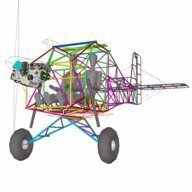
fly_tornado Posted January 27, 2016 Share Posted January 27, 2016 this is what the front end of a tornado looks like after an off field adventure the bottom tubes are supposed to be straight coming out from the floor of the fuselage. as you can see its taken a fairly big hit, and the aircraft stuck in a ditch but the linkages are all intact but a bit bent due to deformation of the frame. Link to comment Share on other sites More sharing options...
Head in the clouds Posted January 27, 2016 Author Share Posted January 27, 2016 this is what the front end of a tornado looks like after an off field adventure ... Thanks FT. My point is proven. I have personally witnessed an aircraft running into a large runway light and then getting airborne with similar damage. As you can see, having sustained that damage the rudder cables are now slack and the steering pushrods are bent. Both of those factors separately mean that the rudder cannot now be controlled by the pedals. Conclusion - bad design ... > > > This thread is intended as the Australian location of the build log for the DooMaw and as such is something of an 'official document'. Most build logs don't permit comment except by the builder but I'm quite happy to have input on the thread that discusses good design and workmanship principles and I'm grateful that there has been some very useful contribution to the DooMaw design by others as a result of the thread being open for comment. However I'd really rather that folks don't use this thread to discuss the relative merits (or otherwise) of material that isn't of specific relevance or benefit to the DooMaw design and construction. I've already given my opinion of the Tornado rudder control design and it's not a positive one, since flexible cables can't be pushed. I will never be convinced that a design like that is appropriate in an aircraft. If you want further discussion of the Tornado design please by all means start a thread of your own about it and I, and others I'm sure, will be happy to contribute there. Thanks. 4 1 Link to comment Share on other sites More sharing options...
Kyle Communications Posted January 28, 2016 Share Posted January 28, 2016 Here here.... piss off FT and annoy another thread...this thread is for actually learning something not a pedastil for your crap 3 1 1 Link to comment Share on other sites More sharing options...
Head in the clouds Posted February 11, 2016 Author Share Posted February 11, 2016 27th January - 11th February 2016 Another couple of weeks. I've turned all those bits into two sets of adjustable pedals. Lots of drilling, jigging, clamping and fiddly small welding later, but I'm happy with the result. It was a bit of a battle to get the brake cylinder cleats properly lined up and uniform so I had to make a small jig from telescoping tubing and threaded rod, shown in the first image. I then made up the parts for the adjuster locking mechanism and it works nicely and is very secure, so there shouldn't be any accidental pedal adjusting happening at the wrong time. While I was in small parts welding mode I jigged up the parts I'd made some while ago for the bellcrank and elevator control horn and welded them, so the elevator centre section is ready for the addition of the hinges and the external horns which carry half of the pylon500 hinges (see post #91) that engage with the elevator control surfaces, and allow the the complete horizontal stabiliser to be folded upwards for trailering without disconnecting any controls. Following that I removed the fuselage from the project bench and put it back on its dolly wheels under the house because shortly I need the space on the bench to build the vertical and horizontal stabilisers and the rudder and elevators. I took a day out of the workshop to do the CAD work and CNC files for all the convoluted plates with myriads of holes in them for fitting the windshield, sheetmetal sides to the forward fuselage, firewall and cowling, and sent them off to the laser-cutting people for them to get started on. The material for that and the next stages of the project should get here in a week or so. Part of the material arriving soon is the thin CRMO sheetmetal for forming the ribs for the tail surfaces, they're .025" (0.6mm) CRMO sheet and it's cut into strips and folded into a C section, parallel 7/8' (22mm) for the fixed stabilisers and tapered 7/8" to 3/8" (22mm to 10mm) for the control surfaces. I had intended to get that sheetmetal guillotined up and folded in a sheetmetal shop but the folding is a fiddly and quite critical business that has caused me grief previously, and there are a lot of instructions to write out if there's to be any hope of them getting it right and not wrecking all my chromoly sheeting. So I'd far rather fold them myself. The problem is that the flanges are too small to fold it in a pan brake. A brake press is ideal but it requires a very narrow bed and not many workshops around here have one that small. I figured that I'd had good success with the tiny 4" (100mm) long brake press I made to go in my baby 6T shop press, for making the folded brackets a couple of months ago, so I thought that since the sheet for these ribs is only half the thickness or less, of the thickness of the brackets, perhaps I could make a much longer brake press the same way and fold them myself. The first problem was getting some control over the bed so that it didn't tilt as it folded, which would end up with one end folded to a much sharper angle than the other end. I won't try and describe how I made that side of it work, the pictures will show it much more easily ... The blade pulled and bent as I welded it of course, because I got the welding order wrong, but I linished and re-ground the edge straight again afterwards and once I got it working properly I folded the dummy tapered rib in the last picture from a piece of scrap colourbond as a test piece. It's worked out perfectly. It looks a bit wavy but that's not the fold, it's just a rough cut with shears along the edge of the sheet - once I get the proper sheeting pieces guillotined it looks like it should do the folding nicely. 77 more hours for the log, a total of 729 hours so far. 6 1 Link to comment Share on other sites More sharing options...
Kyle Communications Posted February 11, 2016 Share Posted February 11, 2016 Stunning work Allan as usual 4 1 Link to comment Share on other sites More sharing options...
Head in the clouds Posted March 6, 2016 Author Share Posted March 6, 2016 12th February to 6th March 2016. How time flies when you're having fun. Another three and a half weeks since the last report but lots of fabricating has been done as well as planning and prep work to get the next materials order worked out, a bit more of the CAD and design work and all that fitted around my real job which is starting to get busier now as the construction industry year gets up steam again. I usually try and make log reports when milestones are reached, in other words when the next part of the build is completed but at the moment I've been working on several things at once so I have quite a number of things that are partially completed. I finished welding the joystick assembly but haven't taken a photo so I'll show that next time. The biggest priority I had was to get the next lot of materials ordered so that took up a fair while just mentally going over all the next stages in the hope of not forgetting to order something or other because the freight costs add 20% or so to every order and they also have minimum order amounts, so you can't just order a single piece of tube or plate that you missed ... anyway I got the order finalised and sent off - another $1000 or so of materials - and as far as I can tell I only forgot a couple of items which can be ordered next time when I get the materials for the wings. I fitted the Rotax ring mount to the engine and roughed out the CAD model of the engine mount, and produced the machining drawing for the rubber vibration isolation carriers. I had them machined as they are a bit heavy for my small lathe. While I was at it I modelled the tailwheel assembly as well. While I was waiting on the freight I set up the HS and VS jigs on the project bench, cut all the tubing, descaled it in the lathe, notched the ends, painted it and welded up as much of it as I could in the jigs. I was limited how far I could go by not having the ribs to install yet. I was able to make a preliminary fit-up of the ventral fin to the vertical fin and match them to the attachment points on the fuselage, adjust them accurately and then weld all in place. It all fits nicely and the two-piece rudder post is straight, which is pleasing, since it only takes one of the legs to be 1-2mm longer than the other to really throw the alignment askew. Next I set up the blocking for the tailwheel support assembly. It's an unconventional tailwheel setup because it will have to deal with rolling over some rough surfaces on occasions as well as being thumped down for landings in confined areas, so instead of the traditional leaf-spring design I have a strong trailing link supported by a reasonably long-travel strut above, which is buried in the aft fuselage structure and attaches near the HS attachment on a cross-member between the top longerons. The completed assembly is shown in the centre of the picture above. The tailwheel fork is a bit more complicated affair than usual too. It's quite a large tailwheel, the tyre is a 3.00x4 on a four inch rim, so it's 250mm/10" diameter and about 85mm/3.4" wide, consequently a sheetmetal wheel clevis large enough to carry it would be quite heavy, especially for the aft fuselage where we like things to be as light as possible. I found a very small tube bender that bends 3/8 tube as tight as 43mm/1.6" c/l radius. It's made of gravity die-cast aluminium and only intended for copper plumbing tube but I managed to make most of the bends in the CRMO tubing before I broke one of the handles, then grafted a stronger and longer handle on and kept going. Some of the bends can be seen on the extreme right side of the pic above. Once the new materials arrived I was able to mark out the guillotining of the thin 0.025"/0.6mm CRMO sheet for forming the ribs for the tailfeathers and have that cut up. Then bend the 5/16 CRMO tubing for the brake pedals, using the revitalised bender, also in the picture above. I deburred and descaled the guillotined rib sheetmetal and marked out the notches in the ends of them, cut them and painted them. Then it was time to re-visit the mini brake press I made a month or so ago. I had some off-cuts to use as practice pieces and found I needed more control of the blade to get both ends of the bends reliably at 90 degrees and also to keep the blade central to the V bed. Clamps, packers and spacers took care of that and it started to make accurate bends. The first part was to go through all of the rib blanks and make a 10 degree bend 3mm/1/8" in from the long edges. This is to protect the fabric from getting worn by the edge of the sheetmetal. Then the 90 degree bends have to be made very accurately because the rib must end up exactly the same width as the diameter of the tubing it will be welded to. The HS and VS ribs are parallel because the front and back tubes are both 7/8" diameter, and the elevator and rudder ribs taper from 7/8" to 3/8" at the trailing edge. Half a day's work and that job was done and the little brake press could be put away as I don't think I'll have a further need for it this project. I fitted and welded the ribs to the VS and they worked out well. I had to drill one rib to accommodate the 3/8" diameter diagonal brace which resolves the tailplane wire rigging loads, and I also added the internal ventral fin web members which prevent the fabric tension pulling the top and bottom chords (tubes) together. Last I started making up some of the endplate/clevis assemblies that attach to the inner ends of the HS to allow it to hinge up for trailering. Another 84 hours for the log, a total of 813 hours so far. 2 Link to comment Share on other sites More sharing options...
Head in the clouds Posted March 16, 2016 Author Share Posted March 16, 2016 7th to 16th March 2016 Just a quick catch-up on the log - This session its mainly been about getting the HS, VS, rudder and elevators built. There's not much new 'technology' to write up, just the usual printed plans off the CAD model, wooden blocks screwed to the bench to hold all the parts in place, careful tack welding each side in several places to prevent it all pulling out of shape when completing the weld runs. Bending the trailing edge tubing (CRMO 3/8"x0.035") required care to make sure it was all bent where the corners were supposed to be rather than a bit long or short, and more particularly so that all the bends were in the same plane i.e. so that it would sit flat on the bench rather than with a twist in it. It all came out well and next I have to add the hinges and the through-tubes that accommodate the bolts for the diamond-brace wire rigging. In the photos below you can also see the endcaps on the HS parts with their cleats which allow the HS to fold up for trailering, fitting them required another small jig to keep them aligned so they hinge up without binding. Last I got back onto making the parts for the hinges. Previously I'd used a grinder and then a flap disk to dress a couple of lengths of 8mm x 10mm key-steel to round off two of the edges, and then cut them up into short lengths ready for drilling. I had a couple of people ask me how I would drill them accurately and consistently off-centre, they expected I'd use the drill press and so I received blank looks when I said I'd use the lathe. That made me realise that not everyone has used lathes and four-jaw chucks, of course. For those that may be interested - lathes don't always have to be equipped with a self-centring three-jaw chuck, you can also fit a face plate which allows you to bolt flat plates (or other things) to the spindle and machine them, or a four-jaw chuck which has jaws that are independent of each other and so can be adjusted to hold things of various shapes and hold them off-centre if you desire. To drill something like my small hinge parts I first set all the jaws to hold a piece of 8mm ground bar-stock central, by adjusting each jaw in turn while measuring the run-out of the bar with a dial-gauge. Once I had that running true within a thou or so I could then back one jaw the required amount off-centre to insert the small hinge blocks. I then taped up the other jaw key-holes, to prevent me loosening the wrong one by mistake as I drill the 40 or so pieces. Because these hinge parts act as bearings we want them just the right clearance on the hinge pins so they are loose enough to rotate freely but not so loose they rattle and cause excess wear. It's a fairly fine line, about 0.0015" is ideal. The hinge pins will be 3/16" AN bolts and they're fairly close tolerance on 3/16" (0.1875") so the next drill size above is a Number drill, #12, which is 0.189". To accurately achieve this size and not get an out-of-round hole we need to drill it with a few steps to the process. One of the pictures below shows the drills I used, first a centre-drill to make sure the hole is at the centre of rotation, then a 3/32" pilot drill, then 3/16" and then the #12 drill. Although the #12 drill removes barely any material it's a good idea to run it through quite slowly so as to produce a nice internal finish to the surface of the hole, that and regular lubrication will prolong the life of the hinge considerably. Another 34hrs for the log - 847hrs so far. 2 1 Link to comment Share on other sites More sharing options...
Oscar Posted March 17, 2016 Share Posted March 17, 2016 Lovely work - as always ( and btw, I just caught up with your pedal set-up - that is a work of art and really clever design - tips me lid!.) Interesting chuck - I've not seen one quite like it with what appears to be a removable front plate? Looks as if it has been faithfully serving you for a long, long time! I have two lathes, an old - like 40 years old - small Tiawanese one, and a Smart & Brown 1024 high precision one which I have not yet managed to get into commission. It has both an independent and a centreing 4-jaw chuck ( and a six-jaw as well), and I'm really looking forward to getting it working. The Taiwanese one was always very inaccurate with the three-jaw, but I adapted the S&B collet adaptor and with a full set of collets up to 1", boy has it made life easier!. The range of things one can do better with a lathe, is very considerable... 1 Link to comment Share on other sites More sharing options...
Head in the clouds Posted March 22, 2016 Author Share Posted March 22, 2016 Lovely work - as always ( and btw, I just caught up with your pedal set-up - that is a work of art and really clever design - tips me lid!.)Interesting chuck - I've not seen one quite like it with what appears to be a removable front plate? Looks as if it has been faithfully serving you for a long, long time! I have two lathes, an old - like 40 years old - small Tiawanese one, and a Smart & Brown 1024 high precision one which I have not yet managed to get into commission. It has both an independent and a centreing 4-jaw chuck ( and a six-jaw as well), and I'm really looking forward to getting it working. The Taiwanese one was always very inaccurate with the three-jaw, but I adapted the S&B collet adaptor and with a full set of collets up to 1", boy has it made life easier!. The range of things one can do better with a lathe, is very considerable... Thanks again Oscar. Yes it's an old chuck that's done a lot of work, that's for sure. But not quite the sentimental old faithful that it might appear. One of my big regrets is that when I went away commercial flying I got rid of my good machinery with the thought that I'd I buy similar again when and if I returned years later. Unfortunately after those years passed it was very much more difficult to find quality machinery than it was in the 1970s and 80s. I did have a nice Swiss milling machine until about 5-6 years ago and a good Taiwanese lathe in the British pattern, but also let them go because they were just a bit too large for current needs, and again I thought I might be able to find something to my taste but a fair bit smaller. No such luck so far, at least not within my rather limited budget. So - a few years ago I needed a small lathe quick-smart for a specific job and just bought a Chinese one off ebay that was the right size, without any thought for its use afterward. I regret I didn't buy the next size up which has a geared head and Norton box for thread-cutting because I detest fiddling with belts and manual change gears for threading and feeding. Also mine doesn't have a powered cross-slide. But worst of all it's an American pattern. In general the American machinery design isn't too bad, after the German and Russian designs in my opinion, with British probably fourth or fifth. However the yanks really did take their eye off the ball with their lathe pattern. Whatever possessed them to control the carriage travel with the left hand, with the consequence of feeding all the hot swarf over that hand, is beyond me. Anyway, the cheapie lathe I bought didn't come with an independent four-jaw chuck so I found one on ebay with a spindle thread that almost matches ... and converted it. It is an unusual construction though it's not so much a removeable faceplate - it just looks like that in the photos because of the 100mph tape I put over the three jaw adjusters I didn't want to move accidentally. But the construction is bolted from the front rather than the usual rear. The chuck originally came from a Hercus or Southbend I think, or possibly a Myford 7. Sounds like your S&B will be a delight when you get it running, I'm jealous ... yes, can't beat collets, particularly for fast repetitive work. Surprised to hear the Taiwanese lathe was inaccurate, I've found them to be quite well made generally, especially considering the price. Mainland Chinese ones are best considered to be a starting point, a kit if you like, from which to start building yourself a lathe by re-machining and adjusting everything except the bed, hopefully ... can't get anything cheaper though, so at least they allow more people to have an entry into machining if they wish. 1 Link to comment Share on other sites More sharing options...
Head in the clouds Posted March 22, 2016 Author Share Posted March 22, 2016 Every now and then we all have a day when everything goes well. And it's said that these things often happen in threes. Well it certainly did for me just recently, and typically they seem to happen just when you've given up hope. Two of my three things aren't relevant to this thread but the third certainly was. I've designed DooMaw to use the Desser 850x6 Aero Classic tyres. They're not quite true Bush Wheels which can probably be described as starting at the 26" Alaskan Bushwheels Airstreak, but they are quite large by LSA standards, and will roll easily over quite rough ground and absorb significant shock. As we all know, anything to do with aeroplane ownership requires a very healthy personal fortune, a friendly bank manager and/or some pretty creditable abilities at finding the best value deals, and the Aero Classics, at US$225 per tyre represent good value. They're a fair step more than the 14" and 15" tyres most LSAs use, for comparison those are around US$60, but they're a lot less than the first of the 'Bushwheels' at well over US$1000 each. So - now it's getting to time to test the gear strut loads and make up the suspension, for the last six months or so I have been trying to get a pair of 850 tyres and tubes over from the US at a reasonable cost. It pretty much looked like the freight was going to double the already significant cost, when taking into account an extra US$80 per tube and the poor exchange rate. In fact, if I bought two pairs of tyres and tubes and could depart at short notice, it was cheaper to buy a discount airfare and go over and bring them back as accompanied baggage, how crazy is that ...? Anyway, I heard that forum member Nick Duncs changed his Bearhawk off 850x6 tyres to the 26" Airstreaks and passed on his 850s to Doug Evans and I found another member who had made a similar 'upgrade'. I sent him a PM and asked if I might buy his 850s to help me avoid this freight problem and I'm still overwhelmed by his response - he said I could have them for the price of a cup of coffee and a chat and a look over DooMaw when he's coming past this way! Well, I've wanted to chat with him anyway, because I've always enjoyed his well considered and interesting posts on the forum, so Thank You again SDQDI, I'm so very grateful - words just aren't enough! Pic below of my fabulous gift - they arrived yesterday by TNT, they look brand new, they don't show any wear on them at all - and they perfectly match the tailwheel I sourced last month. They're certainly a very nice big wheel compared to the 'normal' LSA tyres I already had and which I'd almost resigned myself to having to use for now. The second pic shows the 22" 850x6s, the 'normal' 15"x6 LSA tyres, and the tailwheel for DooMaw with the red hub. Note that the 11" tailwheel is as large as the main wheels were on the very early Drifters - 3 1 Link to comment Share on other sites More sharing options...
Guest nunans Posted March 23, 2016 Share Posted March 23, 2016 Very interesting build, congrats on the ideas and the progress. When you get to the covering stage, since you're after a light weight stol design might I suggest you include Oratex 6000 in your shortlist for consideration. www.betteraircraftfabric.com Link to comment Share on other sites More sharing options...
nickduncs84 Posted March 23, 2016 Share Posted March 23, 2016 Every now and then we all have a day when everything goes well. And it's said that these things often happen in threes.Well it certainly did for me just recently, and typically they seem to happen just when you've given up hope. Two of my three things aren't relevant to this thread but the third certainly was. I've designed DooMaw to use the Desser 850x6 Aero Classic tyres. They're not quite true Bush Wheels which can probably be described as starting at the 26" Alaskan Bushwheels Airstreak, but they are quite large by LSA standards, and will roll easily over quite rough ground and absorb significant shock. As we all know, anything to do with aeroplane ownership requires a very healthy personal fortune, a friendly bank manager and/or some pretty creditable abilities at finding the best value deals, and the Aero Classics, at US$225 per tyre represent good value. They're a fair step more than the 14" and 15" tyres most LSAs use, for comparison those are around US$60, but they're a lot less than the first of the 'Bushwheels' at well over US$1000 each. So - now it's getting to time to test the gear strut loads and make up the suspension, for the last six months or so I have been trying to get a pair of 850 tyres and tubes over from the US at a reasonable cost. It pretty much looked like the freight was going to double the already significant cost, when taking into account an extra US$80 per tube and the poor exchange rate. In fact, if I bought two pairs of tyres and tubes and could depart at short notice, it was cheaper to buy a discount airfare and go over and bring them back as accompanied baggage, how crazy is that ...? Anyway, I heard that forum member Nick Duncs changed his Bearhawk off 850x6 tyres to the 26" Airstreaks and passed on his 850s to Doug Evans and I found another member who had made a similar 'upgrade'. I sent him a PM and asked if I might buy his 850s to help me avoid this freight problem and I'm still overwhelmed by his response - he said I could have them for the price of a cup of coffee and a chat and a look over DooMaw when he's coming past this way! Well, I've wanted to chat with him anyway, because I've always enjoyed his well considered and interesting posts on the forum, so Thank You again SDQDI, I'm so very grateful - words just aren't enough! Pic below of my fabulous gift - they arrived yesterday by TNT, they look brand new, they don't show any wear on them at all - and they perfectly match the tailwheel I sourced last month. They're certainly a very nice big wheel compared to the 'normal' LSA tyres I already had and which I'd almost resigned myself to having to use for now. The second pic shows the 22" 850x6s, the 'normal' 15"x6 LSA tyres, and the tailwheel for DooMaw with the red hub. Note that the 11" tailwheel is as large as the main wheels were on the very early Drifters - [ATTACH]42046[/ATTACH] [ATTACH]42047[/ATTACH] Ah well now I feel guilty! Poor Dougy paid me 500 for mine! about half price what it cost me which I thought was a decent deal! For what it's worth, the ABWs sure are a big difference on the bearhawk, but a big part of that was that I was having to run the 850s at 20psi with the weight of the bearhawk. The ABWs run at 8psi and that's what makes them soak up the ground on landing. I'm sure the dessers at low pressure would be awesome. I've flown the same ones on a cub and they were very nice. Link to comment Share on other sites More sharing options...
pylon500 Posted March 24, 2016 Share Posted March 24, 2016 G'Day HITC, been following the thread off and on and must say I love your manufacturing skills an attention to detail. Having said that, I now and then spot something which, from an outside perspective, I have a little head scratch about but is usually solved by reading the text a little more closely. However, I spotted the detail for your tail wheel drawing as well as the photo of your proposed plastic tailwheel, and feel I should comment again... Being an avid tailwheel driver, I do find people thinking of tailwheels as 'just the little wheel down the back', and then running into problems with them. Obviously when you think about it, a tailwheel is equally important as a nosewheel, as it does the same job, so all it's load factors and dynamics need to be considered as closely as is a nosewheel. To start with, I wouldn't trust the plastic tailwheel hub as far as I could throw it, with or without good roller bearings. While the moment arm of a tailwheel will give it better leverage over the mass of an aircraft compared moment arm/side loads imposed on a nosewheel, the side loads are still significant to be imposed on a plastic hub. I know many use them and get away with it, but I get the impression the 'DooMaw' is being aimed into the STOL/Bushplane operation so robustness is somewhat of a requirement. My other concern is the layout of your tailwheel fork hinge line dynamic. I see these serious 'aft' trail tailwheel on a regular basis, and always question their use...? When asked, designers using them tell me that having a lot of 'trail' in a tailwheel helps keep the plane straight, supposedly by resisting any sideload !? While this sounds about right, what really happens is these tailwheel will happily follow wherever the fuselage is going, unfortunately if there's a crosswind or the aircraft has decided to head off into a ground loop, then the sideloads on this type of layout make it nearly impossible to stop a ground loop without the use of brakes. I find the reality is, these aircraft are usually hard to turn when taxying, being very heavy on the pedals and usually requiring the use of brakes to assist turning. I am also sometimes told long trail tailwheel are less susceptible to shimmy, but I don't believe that, only that the shimmy frequency is lower (but just as damaging). My own 'Stollite' (https://picasaweb.google.com/113292981019876413104/BuildingAndFlyingTheStollite#) uses a modified Lightwing tailwheel where I reduced the amount of trail, and it is very easy to taxi in strong crosswinds without the use of much brake, which is just as well as the brakes (cable operated) are not the best. The pictures show (sort of) the difference in rake or trail in the forks, between a standard Lightwing (red) and the modified (white) forks as used on my Stollite. Sorry for the long winded description of what most people think is a simple item. 1 1 Link to comment Share on other sites More sharing options...
Head in the clouds Posted March 24, 2016 Author Share Posted March 24, 2016 G'Day HITC, been following the thread off and on and must say I love your manufacturing skills and attention to detail .......... Sorry for the long winded description of what most people think is a simple item. Hi pylon500, thanks for the kind words, and please don't make any apologies, I really appreciate your considered and most valuable input based on your extensive real-world experience, thanks for taking the time. I posted this log online primarily in the hope of inspiring someone into considering their own build, be it a kit assembly or a scratch-build - but the great benefit to me for the DooMaw build is the 'peer-review' aspect. I certainly don't know it all and comments people have made have been invaluable. Having said that, I now and then spot something which, from an outside perspective, I have a little head scratch about but is usually solved by reading the text a little more closely.However, I spotted the detail for your tail wheel drawing as well as the photo of your proposed plastic tailwheel, and feel I should comment again... Being an avid tailwheel driver, I do find people thinking of tailwheels as 'just the little wheel down the back', and then running into problems with them. Obviously when you think about it, a tailwheel is equally important as a nosewheel, as it does the same job, so all it's load factors and dynamics need to be considered as closely as is a nosewheel. To start with, I wouldn't trust the plastic tailwheel hub as far as I could throw it, with or without good roller bearings. While the moment arm of a tailwheel will give it better leverage over the mass of an aircraft compared moment arm/side loads imposed on a nosewheel, the side loads are still significant to be imposed on a plastic hub. I know many use them and get away with it, but I get the impression the 'DooMaw' is being aimed into the STOL/Bushplane operation so robustness is somewhat of a requirement. ..... Yup I agree, I'm no fan of plastic wheels either. However it's a value judgement thing for the interim and not intended to be permanent, but it's the best solution I can come up with at present. That said, maybe forumites could help with keeping their eyes out for a better rim? Early days we did use plastic wheelbarrow-type wheels and even plastic bicycle wheels for main wheels, let alone tailwheels, and we generally got away with it until we had a really hard landing, or one with a lot of drift on. Then the bearings would tear out of the hub. Gladly our flying speeds were so low that other damage or injury was unheard of. That said, I spent a lot of time trying to find the tailwheel components I really wanted and this plastic hub is the best temporary solution. It does have better-designed bearing support than any other I have come across in the past, the molded 'spokes' are quite substantial, the hub annular support for the bearings is quite thick, the plastic is cross-linked polyethylene, so it has a reasonable amount going for it compared to the average. It's a Fallshaw wheelchair wheel with a load rating of 90kg/200lbs, I changed the low-speed roller-bearings for high-speed ball-bearings of course. How the rim choice came about was that I really wanted to run that particular tyre which not only has a rib tread pattern but is also 4 ply and has an excellent load rating of 350lbs with a weight of only 0.8kg. The whole wheel, with tube, bearings and bearing compression spacer is only 1.5kg. The only stronger rim I could find that would carry that tyre was a split steel rim which weighs 3kg on its own. So - given that the early proving flights will be conducted off good surfaces and in moderate winds it gives me time to make a better rim. Unless I can find a suitably light cast or spun aly rim I'll have to machine the dies to have one spun and machine up a suitable hub to suit, and if I'm making one I guess there'll be other bushplane owners (Stollies?) who might be interested too. ...... My other concern is the layout of your tailwheel fork hinge line dynamic.I see these serious 'aft' trail tailwheel on a regular basis, and always question their use...? When asked, designers using them tell me that having a lot of 'trail' in a tailwheel helps keep the plane straight, supposedly by resisting any sideload !? While this sounds about right, what really happens is these tailwheel will happily follow wherever the fuselage is going, unfortunately if there's a crosswind or the aircraft has decided to head off into a ground loop, then the sideloads on this type of layout make it nearly impossible to stop a ground loop without the use of brakes. I find the reality is, these aircraft are usually hard to turn when taxying, being very heavy on the pedals and usually requiring the use of brakes to assist turning. I am also sometimes told long trail tailwheel are less susceptible to shimmy, but I don't believe that, only that the shimmy frequency is lower (but just as damaging). ..... Damn ... you got me this time! I certainly didn't treat the tailwheel as 'just the little wheel down the back', in fact I gave it a lot of thought, research and design work, but I obviously took my eye off the ball for a moment and completely missed one vital consideration. Sometime last year I entered into a lengthy discussion on HBA about tailwheels but the majority of the subject was about shimmy prevention and avoidance and I have to admit I allowed that to dominate my thoughts and the overall design, and that, in combination with a need to keep the overall height of the tailwheel assembly as low as possible to maintain the 16 degrees angle of attack on the ground, I completely missed that I was designing in far too much trail length/angle. It's not actually quite as bad as it appears in the image I posted earlier, because that image is shown with the fuselage datum level (level flight condition), rather than at the angle it sits on the ground. When the image is rotated by 13 degrees as it would be when at rest on the ground, it brings the steering rake angle positive instead of negative, but I now realise the trail is still far too much. I'm very grateful that you brought this up now, actually one day earlier would have been better, since as you see from the photos attached, I made up the very complex tubular clevis just yesterday ... ;-( Anyway, I've made a quick adjustment to the CAD model to see what can be done as a fix which still uses the same components. I'll have to cut and shut the tubular steel clevis and add a couple more bends but that's the beauty of welded structures, the very fact that you can do that. The new shape retains the positive rake angle but means the wheel must come forward and be more underneath the steering pivot point - this has several effects. Firstly it greatly reduces the steering loads and massively assists in resisting steering into groundloops due to side loads applied by crosswinds - as you mentioned. Secondly it makes the assembly taller which is unfortunate because it creates more drag and also reduces the static AoA but that latter is not as bad as I thought it would be, it's only reduced by 3/4 of a degree - I can live with that, extreme STOL landings would contact the tailwheel first anyway, and its structure and suspension is designed for that. Thirdly, I had shaped the bottom of the rudder to allow the tailwheel to move up into that zone under full suspension motion before contacting the bump-rubber stop, I can get rid of that 'notch' now - another cut-and-shut job. Very interesting build, congrats on the ideas and the progress.When you get to the covering stage, since you're after a light weight stol design might I suggest you include Oratex 6000 in your shortlist for consideration. www.betteraircraftfabric.com Hi nunans. Yes, covering is in mind at present so peoples' comments and suggestions are most welcome. I've certainly been thinking about Oratex, particularly since it saves dealing with dopes, aluminium coatings for UV protection (which adversely shield the internal part of the VHF antenna I want to use) and, potentially, paint. Though I'm not overly impressed with the colour selections available so would probably choose to paint it anyway. Have you used Oratex nunans? Any experiences to relate? I'm only going to need fabric for the covering of the fuselage and tail aft of the cabin. forward of the cabin will be 0.016" aly sheeting, and I've decided to do the wings with the same, to avoid using twin struts and the extra trouble that would introduce to the wing quick-folding mechanism. ................................. Progress report 17th to 24th March - It's mainly been about completing half-done jobs at the moment. I've been welding on hinges for the tailfeathers and adding the through-tube fittings for the diamond wire bracing. I made up the centre-section of the HS, the complex frame that carries all the hingeing mechanism for the HS as well as the elevator controls. It was critical to get all the hinge alignments right, in three planes, so that the HSs were both 'flat' relative to each other and their rear spars were in a straight line, the individual elevator hinges all had to be in a straight line also, so the elevators would move smoothly up and down without binding and the HS and elevator hinge-lines that allow the whole assemblies to fold up for transport, also have to be concentric so that it folds without binding. The last part of the above complexity was brought about by pylon500's earlier suggestion for the elevator control attachment, and although it was a little awkward to arrange (it required a third jigging to achieve), the benefits are wonderful because there'll never be any risk of forgetting to connect a control after unfolding the wings and tail before a flight. I also made up the brake pedals with their cleats, which go on top of the rudder pedals. Also fitted the new tyres from SDQDI to the Black Max 6" rims I had before, they suit the rims well and the hubs carrying the bearings look quite sufficient. BM do offer a hub that carries bearings for a 3/4" axle as an upgrade to the 5/8" ones that I already have. The brakes though, are another matter. I had been thinking they look rather puny but time will tell. Then I received another extremely kind offer from nickduncs84 who says I can have the rims and brakes he took off his Bearhawk when he fitted the Alaska Bush Wheels. They're Clevelands, and very much more substantial, so many thanks again for such generosity Nick, it's very much appreciated! Some pics - Adding hinges and the through-tubes for the bolts that secure the wire bracing The brake pedals HS flat on the bench with close-ups of the centre section - note the pylon500 hinge, bottom-left in the 4th pic HS in folded position - note the controls are still connected, 3rd pic shows bottom view Tailwheel and the tubular clevis I made up yesterday, 3rd pic shows the 'notch' in the bottom of the rudder to increase tailwheel suspension motion SDQDI's tyres fitted to the Black Max rims - outside, hub side and hub close-up Tailwheel geometry - the first pic is the one posted earlier with the fuselage in flight attitude, the second pic shows how it would have been sitting on the ground, note how this brings the steering pivot angle positive instead of negative i.e. the hinge pin is sloping backward with the top of the pin aft of the bottom, this in combination with the right amount of trail, is necessary to help prevent shimmy. The third pic shows the clevis adjusted to give much less trail and and length - converting what I've already started to make will be today's challenge. This last image shows a bit of what we're trying to achieve for low steering loads and resistance to shimmy. 67 more hours for the log, a total of 914hrs so far. 7 Link to comment Share on other sites More sharing options...
Head in the clouds Posted March 26, 2016 Author Share Posted March 26, 2016 Done - I made up some new bends and cut the tailwheel tubular clevis up to graft them in. Then added the top and bottom bearing plates that connect the clevis to the suspension frame. The geometry is now as near identical as I can make it, to the properly installed Scott tailwheel shown in the last image in the previous post. It was pleasing to find that the whole tailwheel assembly shown in the first picture below only weighs 2.3kg. Since the wheel is 1.4kg that means all the steelwork with bolts and spacers is only 900g. I also cut and shut the bottom rail of the rudder to remove the notch which isn't needed now. Another 10hrs to do that lot - a total of 924hrs so far ... 5 Link to comment Share on other sites More sharing options...
Marty_d Posted March 26, 2016 Share Posted March 26, 2016 I know you must get sick of hearing this, but bloody brilliant work HITC. 3 1 Link to comment Share on other sites More sharing options...
Kyle Communications Posted March 26, 2016 Share Posted March 26, 2016 I am in awe of what you are doing. You know Alan you have been renamed as Leonardo Leonardo DaVinci..the master 1 2 Link to comment Share on other sites More sharing options...
Head in the clouds Posted March 26, 2016 Author Share Posted March 26, 2016 I know you must get sick of hearing this, but bloody brilliant work HITC. I am in awe of what you are doing.You know Alan you have been renamed as Leonardo Leonardo DaVinci..the master Aw ... shucks guys ... Seriously though, I really appreciate the kind words. As others have commented elsewhere, a plane build is quite a long and lonely road so it's pleasing to be able to share the experiences with the forum and good to hear that folks enjoy reading about it. Can anyone say yet that this has encouraged them to consider a build from plans, or a kit perhaps? Or ... shudder ... has it put anyone off? Yesterday afternoon I pulled the fuselage out again, from under the house, and I added the hinges for the tailwheel and the bottom hinge for the rudder. So it's sitting on three wheels now and easier to move around. Today's project is laser-aligning a piece of 7/8" tubing at the aft fuselage so that I can fit the bent and curved saddle brackets that hold the centre section of the HS. If that goes to plan I might do a trial fitting of the new wheels to the gear legs and fit the real gear legs to the fuselage (at present it's riding on temporary short gear legs and small wheels otherwise it won't fit under the house). That might be the cue for a photo-shoot on the lawn if the weather clears up - it was a bit wet overnight. Coming up shortly is making the seat base. It's made from PVC coated polyester, a bit like truck tarpaulin material but lighter weight. It's laced to the cross-bars in the cabin frame and ends up a bit like those old-style spring folding camping chairs. I already have the fabric but I let my industrial sewing machine go some years ago - so does anyone have an industrial or sail-making sewing machine, or know someone who does within 100km or so of Yatala i.e. I'm halfway between Brisbane and the Gold Coast. I'll supply the fabric already cut out and marked up so it should be a straightforward job. 2 Link to comment Share on other sites More sharing options...
Recommended Posts
Create an account or sign in to comment
You need to be a member in order to leave a comment
Create an account
Sign up for a new account in our community. It's easy!
Register a new accountSign in
Already have an account? Sign in here.
Sign In Now