Head in the clouds Posted February 12, 2017 Author Share Posted February 12, 2017 Last weekend I'd hoped to finish the clevises that attach to the spar cleat on the wing, which I'd shown just started last post - but it wasn't to be. I've never been a fan of air-conditioning, I prefer open breeze-ways and fans when necessary but after four or five consecutive weeks of heat-wave I capitulated, so last weekend was spent installing air-con and a roof sprinkler system - the corrugated iron roof doesn't help when the sun's this persistent ... So at least last week was very pleasant in my home office too, I guess I could get used to air-con, just for the very hot times. Anyway back to what really matters - this weekend I did get the clevises finished, at least as far as I can go until I can remove the parallel vise from the mill and fit the rotary table to round off the ends of these, and several of the previous parts. Photos below show the parts and reaming the holes for the pins, they're the last of the fittings for the upper end of the struts, and now I'm back to CAD for modelling the lower end fittings. They're a lot simpler than the ones I've just finished so we should be getting back to some more visible progress soon. Another 13 hours in that, it probably should have taken less than that, but in this heat ... making a total of 1419 hours so far. Incidentally, the second anniversary of 'laying the keel' of DooMaw was last month. I hadn't expected the build to last more than two years but I've just been too busy with my 'real' work, to get enough time to work on the plane. Normally I have a couple of quiet months over the Christmas period but this year it was full on, I just managed four days off and then it was back to it again. So at this rate it might be another year before we're test flying. Never mind, making hay while the sun beats down relentlessly, so to speak. 4 Link to comment Share on other sites More sharing options...
Blueadventures Posted February 12, 2017 Share Posted February 12, 2017 Last weekend I'd hoped to finish the clevises that attach to the spar cleat on the wing, which I'd shown just started last post - but it wasn't to be.I've never been a fan of air-conditioning, I prefer open breeze-ways and fans when necessary but after four or five consecutive weeks of heat-wave I capitulated, so last weekend was spent installing air-con and a roof sprinkler system - the corrugated iron roof doesn't help when the sun's this persistent ... So at least last week was very pleasant in my home office too, I guess I could get used to air-con, just for the very hot times. Anyway back to what really matters - this weekend I did get the clevises finished, at least as far as I can go until I can remove the parallel vise from the mill and fit the rotary table to round off the ends of these, and several of the previous parts. Photos below show the parts and reaming the holes for the pins, they're the last of the fittings for the upper end of the struts, and now I'm back to CAD for modelling the lower end fittings. They're a lot simpler than the ones I've just finished so we should be getting back to some more visible progress soon. [ATTACH]48427[/ATTACH] [ATTACH]48433[/ATTACH] [ATTACH]48429[/ATTACH] [ATTACH]48430[/ATTACH] [ATTACH]48431[/ATTACH] Another 13 hours in that, it probably should have taken less than that, but in this heat ... making a total of 1419 hours so far. Incidentally, the second anniversary of 'laying the keel' of DooMaw was last month. I hadn't expected the build to last more than two years but I've just been too busy with my 'real' work, to get enough time to work on the plane. Normally I have a couple of quiet months over the Christmas period but this year it was full on, I just managed four days off and then it was back to it again. So at this rate it might be another year before we're test flying. Never mind, making hay while the sun beats down relentlessly, so to speak. Have you considered trunking some cool air from the house to your work shop? Thanks for the update I enjoy your posts and like your quality of building. Regarding fastenings through the aluminium parts have you read the specs for the anti corrosive paste 'TefGel'; I believe it would be worth a read when you have time. Cheers Mike Link to comment Share on other sites More sharing options...
Head in the clouds Posted February 12, 2017 Author Share Posted February 12, 2017 Have you considered trunking some cool air from the house to your work shop? Thanks for the update I enjoy your posts and like your quality of building. Regarding fastenings through the aluminium parts have you read the specs for the anti corrosive paste 'TefGel'; I believe it would be worth a read when you have time. Cheers Mike Hi Mike, thanks for your comments. Unfortunately the workshop is away from the house and also isn't sealed, the walls are just timber slats, so it's nice and breezy but impossible to heat or cool, just an awning out the front helps to increase the shade. It's not much of a problem though, I have fans in there and use them all the time except while welding - still air required while welding CRMO, of course. I'd not heard of Tef Gel, thanks for bringing it to my attention, it sounds like a great product. I've used plenty of corrosion inhibitors and lubricants for dissimilar metals, and particularly for things in a marine environment. I've generally found Duralac to be excellent for assembling dissimilar metals where they don't move i.e. fasteners of all kinds, and I use nickel anti-seize, white lithium grease or lanolin (or a combination of them) where parts move against each other, but this Tef Gel sounds like it does it all. I really like it not being toxic (and that it's an Australian product) because although Duralac does a fabulous job it's pretty harmful to the respiration system and the aquatic environment. I'll give Tef Gel a try and let you know what I think of it. Link to comment Share on other sites More sharing options...
Blueadventures Posted February 12, 2017 Share Posted February 12, 2017 Hi Mike, thanks for your comments.Unfortunately the workshop is away from the house and also isn't sealed, the walls are just timber slats, so it's nice and breezy but impossible to heat or cool, just an awning out the front helps to increase the shade. It's not much of a problem though, I have fans in there and use them all the time except while welding - still air required while welding CRMO, of course. I'd not heard of Tef Gel, thanks for bringing it to my attention, it sounds like a great product. I've used plenty of corrosion inhibitors and lubricants for dissimilar metals, and particularly for things in a marine environment. I've generally found Duralac to be excellent for assembling dissimilar metals where they don't move i.e. fasteners of all kinds, and I use nickel anti-seize, white lithium grease or lanolin (or a combination of them) where parts move against each other, but this Tef Gel sounds like it does it all. I really like it not being toxic (and that it's an Australian product) because although Duralac does a fabulous job it's pretty harmful to the respiration system and the aquatic environment. I'll give Tef Gel a try and let you know what I think of it. Hi No worries. This is what the forum is all about sharing and learning stuff. TefGel is used where you would use Duralac. I've got many years experience using and getting Duralac every where. TefGel is used heaps on the rivets and fastenings for example yacht masts etc which are under load. I use it on my spar to jury strut connections etc and all going well will be a good corrosion proof barrier. Cheers Mike 1 Link to comment Share on other sites More sharing options...
Head in the clouds Posted February 20, 2017 Author Share Posted February 20, 2017 Another weekend of machining ... OK, I've had enough of it for now and am looking forward to getting back on the fabrication again. I'm on to the lower strut end fittings now. The first four pictures show the parts which fit into the CRMO clevises each side of the fuselage, the last picture shows the billet for the last of the strut end fittings which are the parts that attach to the ones in the first four pics. They will be bolted inside the lower ends of the struts. I have sawn away the excess material on the bandsaw and that last piece is now in the mill ready for next time. But - I'm going to have to make some adapters too. I had a bit of an awakening last week - I have to admit that I'd never given a great deal of thought to the amount of dihedral at which to set the wings. Previously I've always given low wing planes 3 degrees per side and high wings 1.5 degrees per side - simply because that fairly closely matched what you see on 'average' planes. And that probably works closely enough as long your new plane is very 'average' but in this case, DooMaw isn't very average at all. DooMaw has a proportionately very large fin and rudder, nothing is very average about the wing and it also has a wide, tall and boxy front end. I'd not considered that these things could very significantly affect the amount of dihedral that should be rigged. Also - I'd always thought that dihedral really only just provided a degree of directional and 'self righting' stability but I've recently been appraised of the fact that there's a heck of a lot more to it than that, and getting it wrong can be quite dangerous. And if not so far off as to be dangerous, conversely getting it right can make the difference between a plane that is a delight to fly, or just rather average. In short, having too much dihedral causes the horrible weaving tendency called 'dutch roll'. If that was all, perhaps you could live with it even though it causes pretty major airsickness issues, but it isn't as simple as that. Too much dihedral and the aircraft will not return to equilibrium, the dutch roll will amplify and the aircraft potentially become uncontrollable. At the other end of the scale, an aircraft with too little dihedral will have 'spiral instability' meaning a tendency to roll into a spiral dive when flown hands-off, rather than having a tendency to return to level flight. In practice most planes are set up to have a small amount of spiral instability, since it is preferable to dutch roll and both vary greatly with power settings, CoG position, speed, weight etc, BUT the amount of spiral instability must be very small - in the worst case of power/weight/CG/speed, the time to double the rate of change heading must not exceed 10 seconds. I must say a special thank you to the forum member who brought this to my attention - thanks again Oscar! And also a special thank you to aeronautical engineer Dafydd Llewellyn for taking time to provide me with References and other assistance in this not often discussed matter. What a shame Dafydd doesn't frequent this forum anymore, his experience and assistance was one of the best things here for many of us who design our own ... Dafydd also took the time to give me an insight into the necessary steps for determining the right amount of dihedral and it involves a lot of flight testing with adjustment between flights to accumulate data. Consequently, initially I will need struts that are easily and quickly adjustable for length, so I will have to make adapters for the strut-ends I have made, which will fit into telescopic tubes for the initial testing. Once we know the exact length for the struts I can cut the streamline-shaped extrusions I received recently and fit the ends to them instead. Another 15hrs to add to the log, making a total of 1434 hours so far. 3 2 Link to comment Share on other sites More sharing options...
Head in the clouds Posted March 6, 2017 Author Share Posted March 6, 2017 On Thursday and Friday 23/24th Feb I finished off the lower strut fittings I'd shown started in the last post then I spent the weekend of 25/26th Feb machining again and finally completed all the strut parts. The last part of the job was to radius the ends of them which involved removing the parallel vise and fitting the small rotary table I mentioned a few posts back. This rotary table is a real toy. It's only 4in/100mm in diameter and, as purchased, doesn't rate better than unusable junk. I used to have a very solid, high precision Swiss made 300mm/12inch rotary table that had no detectable backlash and a 4inch spindle with widely spaced bearings providing great rigidity. Unfortunately someone must have needed it more than me and it must have been quite an achievement running off with it 'coz it weighed upwards of 60kg ... I don't often use a rotary table so I wasn't going to pay a couple of thousand or more to replace it right now, and as this current job was only on a few small aluminium components I bought this little 4 inch rotary table on ebay for $150. I didn't skimp entirely, there was a smaller 3 inch one for $100. When it arrived it looked superficially OK but the outer casting hadn't been machined parallel at the hold-down points so the first thing I did was clamp it in the vise on the mill and fix those. Next I had a look at the tiny 'hand-wheel' that you were supposed to use to turn it around. That might have been half OK if you just wanted to use it to change the angle of machining once or twice, but it wasn't going to be any good to turn the workpieces back and forth through 180° a few hundreds of times. Additionally, there was about 15° of backlash in the worm-drive which could do with fixing. And ... after I had turned it this way and that a few times the table became loose and rattly. The cause of that proved to be that the spindle only had a single bearing and any rigidity of the whole unit relied on a tiny machine screw under the unit fighting against a single-row ball-bearing and clamping the table against the housing. Tighten it and you got some rigidity but couldn't turn the table, loosen it and the whole thing rattled and wouldn't hold the workpiece against the machine cutting loads. It just shows that Chinese stuff is like Rolls Royce compared with Indian. Anyway, I pulled the whole thing apart and treated it like a kit of parts to use to make something half reasonable that might just go the distance to do the current job, and in the end that proved to be the case, it was getting loose and rattly again on the last two components. The pictures show the modified rotary table with a large crank handle to rotate it back and forth. The bronze sleeve acts as a coupling for the handle as well as a bushing to control the backlash. I had to use the mill to make the T nuts to clamp the workpieces down, I couldn't find a local source of them as small as that. I also machined a hole in the centre of the top of the table and threaded it to fit a sleeved bolt which the workpieces could locate onto to ensure that they were concentric when clamped down. The last few pictures show the workpieces clamped in place for machining and the finished items. Another 25hrs for the build log making a total of 1459hrs so far. 5 Link to comment Share on other sites More sharing options...
Marty_d Posted March 7, 2017 Share Posted March 7, 2017 As always HITC... a work of art. 1 Link to comment Share on other sites More sharing options...
Oscar Posted March 7, 2017 Share Posted March 7, 2017 in the worst case of power/weight/CG/speed, the time to double the rate of change heading must not exceed 10 seconds. HITC - fantastic work, as always. But a small correction to the above: the time to double the rate of change of heading MUST exceed (or at least be no less than approximately) 10 seconds. Easy mistake to make when typing, to add the 'not' - ( I suspect we are conditioned to write 'must not' more often) but when you think about it, it's obvious - the aircraft MUST NOT screw itself into ever-faster turning at a rate too fast for the pilot to catch up with! I think you got the first version from DL, and he corrected it soon afterwards - and in long emails it's so easy to miss one changed word - but that word is important here! If anybody is thinking of trying to check their own aircraft out of curiosity, or looking for improvements in stability / flying characteristics, I urge them to get advice from an experienced test pilot as to how to carry out the tests safely. Test pilots do not - despite the romantic notions shown in some movies or written in some books - just blaze off into the ether and 'wring her neck to see what happens'. There is a reason why they wear parachutes and have spin recovery chutes ( and nowadays, BRS as well, if possible) - because bad stuff sometimes happens. Ask Keith Engelsman - he's had to use a spin-chute in anger..! And it's worth remembering, Cessna lost TWO (I believe) Skycatchers in testing, so if Cessna can't always get the design right, I wouldn't bet on anybody else always getting it right every time, either - just personally.. Edit - sorry about the vast use of red text, but I can't seem to change it as an edit. 1 1 Link to comment Share on other sites More sharing options...
Head in the clouds Posted March 7, 2017 Author Share Posted March 7, 2017 ... But a small correction to the above: the time to double the rate of change of heading MUST exceed ..... Hi Oscar, yes you're right, I copy/pasted small segments of the invaluable info from DL and did notice that I'd included the error, and then forgot to correct it afterwards! And thanks again to both you and Marty for the kind words. I must say I'm pleased to have completed the machining for now and I'm back into some fabricating work now, I'll post some more about that shortly. Link to comment Share on other sites More sharing options...
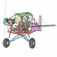
Head in the clouds Posted March 30, 2017 Author Share Posted March 30, 2017 30th March 2017. As mentioned in my last post I got back into fabrication, briefly, and installed a cross-member and a couple of triangular plates above the seat-back to support the headrests/restraints. That was the last welding on the airframe, that I could think of, which allowed me to start preparing to get the epoxy coat on and stop having to constantly monitor for rust and clean and re-prime areas where any surface colour starts to show up. Then I've had a few weeks distraction messing about with boats which made a nice change, must make a point of doing that more regularly, all work and no play makes HITC a dull boy, and all that. Over the last few days the weather has been good for painting so I have made a start on that. So far I have painted four of the six tailfeather panels and the rudder pedal assemblies. It's going well and the small HVLP gravity feed spray guns I bought a while back are working very well with the quite high viscosity of the epoxy. I had to completely disassemble the pedal assemblies for painting of course, and yesterday I was able to start the re-assembly of them. It was a pleasant realisation that doing so was the first final assembly of the whole project, and the real nyloc nuts were used instead of the temporary ones because it's not envisaged that they be removed again for a very long time. As a record for posterity, the rudder pedals were assembled onto their tube-on-tube pivots with Quicksilver 2-4-C marine grease (with ptfe) which should not need servicing for ten years/1000hrs whichever is sooner. Other similar pivots (walking beams, control surface hinges for example) will need occasional oiling (100hr intervals) but I didn't want to provide oiling points on the rudder pedals because excess oil would leak out over time and make a mess of the plywood cabin floor. The other oiling points are much smaller and can be lubricated during servicing and then the excess wiped clean to prevent soiling the inside of the fabric covering. The pictures show - 1. The installed headrest supports 2-5. All work is meticulously checked by the resident workshop Inspectors and Chief Supervisor 6. Partially completed rudder pedal assemblies 7. First stage of painting - getting right into the acute angles with a small brush to ensure rust doesn't develop in hard-to-access corners, it'd be virtually impossible to remedy later if that was to occur. 8. Painted tailfeather components. Including the fabrication, welding, prep for painting, and painting, there's a total of 37 more hours for the log, making a total of 1496hrs so far. 6 Link to comment Share on other sites More sharing options...
Oscar Posted March 30, 2017 Share Posted March 30, 2017 Lovely work as always, HITC - and I note the Resident Inspectors have bought the apprentice in straight out of the nest.. In my experience of them, the apprentices never bloody stop asking questions - mostly: 'where's the food, Mom?' 1 Link to comment Share on other sites More sharing options...
Methusala Posted March 30, 2017 Share Posted March 30, 2017 Love your inspectors HITC. Ours are equally helpful, Don 1 Link to comment Share on other sites More sharing options...
Head in the clouds Posted July 1, 2017 Author Share Posted July 1, 2017 1st July 2017. To get me out of the workshop for a while my wife suggested we might have a change and do some messing about in boats. We rented a bareboat Cat in the Whitsundays and took the family for a much needed change of scenery. That got the sailing bug back in our blood so I finished a refit of a small yacht I had bought back in January and we spent the rest of the summer weekends sailing with friends around the local islands, bays and broadwater. The cool seabreezes were certainly a very pleasant change from the constant heatwaves we experienced this season. Fully refreshed I pulled the covers off DooMaw again a fortnight ago and added the aileron control horns to the control torque tube and set to work prepping all the remaining parts and the fuselage frame to get it ready for painting. I recalled that I'd bought the epoxy paint last March (15 months ago!) because I wanted to get it painted before that winter set in, partly because I was concerned that the winter might be too cool for the epoxy to cure before nightfall, and partly because the damp winter nights would encourage corrosion, for which I'd have to remain on constant alert. In the end that's what happened and I've spent the last year regularly checking the top surfaces of the frame and parts for any signs of rust on the surface. Even though everything is covered with two layers of tarpaulins, every now and then a hint of brown will show on the etch primer and it's out with the scouring pads, polish back to bright metal and then etch prime again. The data sheet for the etch primer says to top coat it within three months and that's proven to be just about how long it provides corrosion protection even when covered with tarps. I pulled all the control system and tailwheel components off the fuselage frame, used thinned paint to slosh paint the inside of any open tubes, prepped and painted all the parts with epoxy, and set to work on the fuselage prep, then painted the frame in four daily sessions rotating it each day. It was a lot more work than I'd ever expected, six very long and strenuous days in all, there are a lot of metres of tubing in all that. I was pleased that I'd started with painting the tailfeathers some months ago because as I've progressed I've got to know the paint and spraygun requirements better each time, so by the time I got to the fuselage frame it was all going quite well. At first, when I was doing the tailfeathers I followed the paint manufacturer's recommendations (Jotun) and the spraygun manufacturer's settings guide but by the end I had ventured a long way from both. The recommendation for the epoxy was strongly against thinning more than 10% but at that it just came out of the gun in large droplets so had to be applied quite heavily to get a good coating. I was concerned that if I thinned it more then it might not cure properly, or not adhere as well, or the coating might not be tough once cured, so I made some experiments with from 5% up to 50% thinning and those samples don't show any difference between them for any of those areas of my concern. Except, of course, that I can get a good even coating much thinner with the more thinned paint. In the end I settled for thinning at 25-30%. As far as the spraygun was concerned I just set it a slightly higher pressure than recommended and adjusted the paint flow rate according to the size of spray pattern I required at the time. Those little gravity feed HVLP guns are a real pleasure to use once you get all the variables working in your favour. I've often read peoples' comments about how much weight paint adds, so that is one of the reasons I wanted an even coat without having to pile highly viscous paint on. To that end I also weighed and kept a total of all the paint I mixed and it came to just 1.5kg plus the thinner. I'm assuming the thinner evaporates off so there's no need to count its weight. I also had about 150g in total left over after the various sessions. And, at a guess, I'd say that at least 30% would be accounted for as overspray i.e. did not land on the airframe. So, on that basis I'd say the total weight of paint added at this stage would be about 1kg. That's fairly well borne out by the remaining epoxy in the cans, I started out with 2x 2lt cans and now there's about half left, and I also painted another project with about 400g of it. So - for now the painting is over and I can get on with a whole gammut of new bits and pieces to make and as they get made they can go straight into final assembly, I finally feel like the fuselage is on the home straight. My brother commented that "it's very white ...", some may recall that I chose that for the steelwork because it would quickly show up any corrosion if that were to happen (CRMO is terrible for rusting if any of the coating gets damaged). The rest of the paint will not be white, so the bright glare should tone down soon. A couple of pics - That's another 58hrs for the log, making a total of 1554hrs so far. 7 Link to comment Share on other sites More sharing options...
Head in the clouds Posted July 24, 2017 Author Share Posted July 24, 2017 24th July 2017 I was keen to get on with the 'final assembly' of all the parts I'd made and painted, and quickly discovered that I need to make, paint internally and install the metal skins to the forward part of the fuselage before I can fit the floors, and I can't fit the rest of the internals - controls etc - before the floors are fitted, and I can't fit any of that until the forward fuel tank is installed. So - a little change of the order of things and I've been working on the tank and forward skins. The tank is just a metal box of 5005 alloy which is not quite as corrosion resistant as 5025 but is a lot less prone to stress cracking and since the installed tank is well protected from environmental issues, the 5005 is the better option. Both of those alloys have good welding qualities. The tank is made from 1.6mm thick material and I don't have a bender or brake press so I cut out the panels with a 'meat-axe' (multicutter - the best and most effortless way to cut aly in my mind, but potentially the most dangerous hand-tool known to man, hence its nick-name), beat the flanges over the rounded edge of the bench and used the fluting pliers to shrink away the curvature caused by the stretching of the flange during beating it, much like making a wing rib. The tank won't be subject to any significant flexing or vibration because it will be mounted using tensioned straps with rubber between it and the straps or any part of the fuselage frame, so I made the tank 'rigid' with internal lap-welded, rather than external edge-welded flanges. It all went together fine. Though I've not done a lot of aly welding so my technique didn't make the welds as pretty as I'd have liked but I'm quite confident it's structurally sound and fully sealed. It will be pressure tested before installation so that will tell the tale. There's a temporary tab tacked to the side of the tank, that's to attach the welder's 'earth' lead while fabricating it, and since the installed tank will be electrically insulated by the rubber mounting I'll need something similar to attach an earth bonding strap in due course. There will also be an 'appendage' added to the bottom of the tank which will form the sump, pick-up point and also add another 9lts to the total volume of 61lts. Additionally there will be two other smaller tanks behind the seats and under the baggage container, each about 25lts, which can transfer fuel to the main tank and which will be easily removable, so that they can be used as jerrycans to collect fuel from a servo or whatever. A few pics of the early stages of the main tank - 22hrs for the log, 1576 so far 4 Link to comment Share on other sites More sharing options...
Kyle Communications Posted July 24, 2017 Share Posted July 24, 2017 Allan we used this stuff at work to make sure all the welds were sealed. If it leaks it comes out of the weld a purple/red colour. There were welds you would swear blind they were perfect but ended up having tiny pinholes in them. I will find out tomorrow at work what it is. They use it for the race car/bike fuel tanks they make for their "after hours" hobbies :) Link to comment Share on other sites More sharing options...
Head in the clouds Posted July 24, 2017 Author Share Posted July 24, 2017 Allan we used this stuff at work to make sure all the welds were sealed. If it leaks it comes out of the weld a purple/red colour. There were welds you would swear blind they were perfect but ended up having tiny pinholes in them. I will find out tomorrow at work what it is. They use it for the race car/bike fuel tanks they make for their "after hours" hobbies :) Hi Mark, yes, I think you're probably referring to a dye penetrant which is excellent for finding a leak if there is one. Good for showing up microscopic cracking too. When making tanks I prefer to pressure test first because that will show up leaks that even dye penetrant won't, because the size of gaseous air molecules is a lot smaller than the liquid dye penetrant molecules. All that said, I've made a few tanks for boats and only once had a small leak, that was a tank that I welded with MIG rather than TIG. The pressure test showed that there was a leak and it was quite easy to find it with bubbles from soapy water. I hope I'm not proven wrong but I'm fairly confident there won't be any problems with this one ... Link to comment Share on other sites More sharing options...
Head in the clouds Posted July 28, 2017 Author Share Posted July 28, 2017 29th July 2017. As I mentioned last time, I have to make and install the forward tank and the forward outer metal skins before I can install the floors. Once all that's done I can get on with assembly of the controls and interior. I templated the skins using some light card from the local stationery shop and then transferred the pattern onto the 0.016" 6061T6 sheetmetal, cut them out, drilled, bent etc and that's another tedious job out of the way. While I was messing with sheetmetal I also made up the firewall. It's 301 stainless, half hard, also 0.016" thick. Stainless is depressingly heavy after all the effort one puts into keeping everything as light as practicable, then having to install heavy material for safety. Such is life. Having made the firewall at least I'll be able to go on and make up the engine mount when I next have some time on my hands. A heap of time in doing this, much of it was spent getting the protective plastic film and adhesive off because the sheet has been sitting around for years. I did find a good way to achieve it in the end, scrape the plastic film off with a razor scraper - surprisingly it didn't scratch the metal but it did leave the adhesive behind, I guess that's what protected the surface of the metal. Then spray the adhesive with mineral turps which turned it into a non-sticky gel which was easily removed with a plastic 'credit-card' scraper. A few pics - 27 hours for the log, 1603 so far. 3 Link to comment Share on other sites More sharing options...
Marty_d Posted July 29, 2017 Share Posted July 29, 2017 Beautiful work as always HITC! 2 Link to comment Share on other sites More sharing options...
facthunter Posted July 29, 2017 Share Posted July 29, 2017 Yes, but how's the weight going? (The Plane's I mean). Nev Link to comment Share on other sites More sharing options...
Head in the clouds Posted July 29, 2017 Author Share Posted July 29, 2017 Yes, but how's the weight going? (The Plane's I mean). Nev I havent weighed it yet but think it's going as well as it can, given that airframe strength is the first priority. Two reasons for that, crash survivability and general ruggedness for off-airfield operations - it's a bush plane first and foremost. There's 60kg of chromoly tube in it so far, 2kg of welding filler rod, 1kg of paint, about 2kg of aly sheet, about 2kg of ss sheet, 2kg of ply for the floors, the tank will be about 5kg and about 3kg of mass balance weights - so there's not much to be saved given that all of that is essential. The wheels and brakes are really light, about 3kg in total, but the big tyres are 6ply and pretty heavy, about 7kg each IIRC. There are lighter bush tyres but the advantage of these - very generously donated by SDQDI (thanks again mate!) - is that they have enough tread rubber thickness to not be punctured by goathead thorns. Hundreds of them have tried already in the tyres' earlier life ... I've lost 11kg since I started the build (and feel much better for it too) so that helps I guess. 2 Link to comment Share on other sites More sharing options...
facthunter Posted July 29, 2017 Share Posted July 29, 2017 Keeping a running tally of everything that goes into it is a good idea. I don't have any concerns about your build quality, Its just that making it strong usually gets heavy as one usually adds a gusset or two extra when modifying/building. Nev Link to comment Share on other sites More sharing options...
Oscar Posted July 30, 2017 Share Posted July 30, 2017 Keeping a running tally of everything that goes into it is a good idea. I don't have any concerns about your build quality, Its just that making it strong usually gets heavy as one usually adds a gusset or two extra when modifying/building. Nev Nev: no argument on that!. If there were ever a case where 'look after the grammes, and the kgs. will look after themselves' applies, it's in aircraft. But - as with everything to do with optimised design, there are compromises. Intelligent use of FEA makes those far easier to rationalise than just old 'by eye' engineering, which is one reason, I believe, that the performance of RAA-class aircraft has improved very considerably while keeping within the stupid, and arbitrary, weight limits (but that is another long story..) HITC's selection of Stainless for his firewall, is an example. Weight for area, s/s is considerably more than mild sheet..But Wait: There's More! ( and no free steak knives involved). I've been rebuilding our ST1 ( an LSA55 Jab. built for VH-compliance). The LSA55 has a 10mm thick ply forward bulkhead, which is a major structural member of the airframe. On the FWF face of this, is normally a galvanised sheet steel firewall of, from rough memory, about .035". I believe that would meet the FAR requirement for 30 minutes (I think it is) of engine fire. Due to modifications to replace the original nosegear with later-series 'heavy-duty' nosegear done by a bloody butcher of an L2, we decided to replace the firewall entirely to eliminate the holes in the firewall that would allow fire penetration aft of the firewall into the bulkhead - and our feet. We did this using .024" s/s sheet, backed with 1.2mm Friberfrax with an additional layer of .016 6061 sheet to support the Fiberfrax across the quite large cut-outs in the actual ply bulkhead. All mounted with 4mm s/s cap-head machine screws through the bulkhead ply, to prevent heat transfer into the ply - rather than the 3/16" commercial-grade alloy rivets used on the original firewall installation. Plus stainless washers under the engine mounts to prevent compression of the Fiberfrax. Overkill, since that combination easily exceeds the FAR spec. BUT: we weighed what we added - and it added about 800 grammes in total over the Gal. sheet firewall. That's a wee bit more than 1 litre of fuel reduced to keep within MTOW ( or about 5 minutes of flight at cruise power, a reduction in range of about 6Nm. ). On the upside, however: in the case of a fire, we would not get burning zinc fumes filling the cockpit (toxic..), nor charring wood fumes ( nauseous, at least), and removing those would - we decided - give us better options for selecting a forced-landing site. It's a risk-management decision: we decided to sacrifice range for the ability to have a better chance of actually getting down safely (or at least, minimally-injured). We could be accused of being paranoid about being fried, since AFAIK there have been zero incidences of a Jab. engine fire. Call us worriers, but we don't want to be the first case, with a bad outcome. Jabiru have moved to using s/s as their firewall material post the LSA55, so I rather think we have the expert's decision-making on our side here. S/s has a far better resistance to heat transfer than mild sheet, so it the case of DooMaw, given the tank is just behind the firewall, I personally would have chosen s/s.. 1 Link to comment Share on other sites More sharing options...
facthunter Posted July 30, 2017 Share Posted July 30, 2017 Yes My Fisher had zinc, Was registered exp in the USA. Stainless is a better refractory metal, especially polished on the fire side. Wood has surprisingly good heat (ed) performance for a while unless it has a forced draft of air on it to make it burn fast. Engine oil will fuel a fire well. You should have some way to cut the fuel completely on your side of the firewall. I am great believer in good firewalls. There should be more building going on. Nev 1 Link to comment Share on other sites More sharing options...
ClintonB Posted July 30, 2017 Share Posted July 30, 2017 Last weekend just replaced my 1mm alloy one with a 0.016 s/s one. Removed all the unnecessary holes, grommets in all the others, tightly sealed. I'm a little more confident in the fire resistance now. HITC, liking your build. It's giving me assurance that a the improvement I'm doing to the Bushbaby is on the right path to making it sturdier. 1 1 Link to comment Share on other sites More sharing options...
BrianG Posted October 1, 2017 Share Posted October 1, 2017 Gents, I have some comments on leak testing in this thread that may be helpful. I recently needed to leak test two wing tanks and the main tank for a Dakota Hawk I am building. I first used balloons filled with air (a safe low pressure test) and looked for bubbles. Aircraft grade Balloons and bubble liquid were bought from the local party shop. I found one very small leak. The chaps in the club were a bit sceptical about this test so I went back to the party shop for some helium filled balloons. ($1 each) I fortunately have access to a helium sniffer gun. This is a very sensitive method. The Helium molecule is small and if there is a path is will escape. It will pick up your breath if you don't brush your teeth. By this method I quickly found a second leak. On redoing the bubble liquid on the second leak, and knowing where is was, I could just see it. My conclusion is this. You can miss small leaks by immersion in a water bath (the supplier did). An air pressure test with bubble liquid is good but you have to go over every joint very slowly and carefully in order to see a small leak. Helium and a sniffer if you have access to it is the best. It also is a way of sometimes testing in position as the instrument probe has a long nose for sniffing and a small vacuum pump. The instruments voice gets squeaky (beeps) if it finds a leak in the vacinity. I made the mistake of not washing the bubble liquid off and it dried and it has marked the aluminium so there must be some chemical in there. I suggest you wash off with water immediately afterwards. 1 Link to comment Share on other sites More sharing options...
Recommended Posts
Create an account or sign in to comment
You need to be a member in order to leave a comment
Create an account
Sign up for a new account in our community. It's easy!
Register a new accountSign in
Already have an account? Sign in here.
Sign In Now