Head in the clouds Posted December 23, 2015 Author Share Posted December 23, 2015 ....... Do you sometimes go to bed with some detail problem niggling away in the back of your mind, and wake up in the early morning with 'the answer' suddenly hitting you? I damn well do, and sometimes it's 'the answer' to something that I hadn't registered as a problem. Maybe builders are subliminally obsessive by nature (aka 'weird'). Yup, I'm afraid there are certainly traces of nuts OCD in this household ... My day job also involves a lot of quite complex problem solving and I would estimate that more than half of the answers come to me while sleeping. At one stage I used to keep a notepad by the bedside, but later found that I always recalled the thought in the morning, if not immediately upon waking then at least within an hour or two, so that saved a lot of scribbling notes in the wee small hours. And yes, I know what you mean about discovering the answer to a previously unperceived problem too - a marvellous thing is the brain, working away studiously while the rest of the organism is asleep. 1 1 Link to comment Share on other sites More sharing options...
Oscar Posted December 23, 2015 Share Posted December 23, 2015 HITC - I'm SO glad that your comment shows I am normal ( for a given value of 'normal')... A wee story that might amplify.. ( and I suspect you'll have a good chuckle about). We replaced the fin and rudder on our damaged ST1 ( basically, an LSA 55) with a UL450 fin and rudder, which is considerably larger for both. This was done in consultation with Rod Stiff ( who graciously supplied us with a suitable fin and rudder at a very decent price, I must add), Dafydd Llewellyn and Alan Kerr, so it wasn't just a brain-fart on our part.. We duly put it on, faired it in, did a limit-load test etc. We were ever so careful to keep the Jab. supplied string for pulling the static line through the opening at the top of the fin in place. What we forgot, was to run that string through BOTH the 'saddle' in the top of the fuselage cone AND the dorsal fin extension on the fin... Cue several hours of me inserted into the rear of the fuselage cone, upside down and with sod-all room to move, to rectify that small oversight. THEN, we found that the holes in the UL 450 fin ribs are 'interestingly' disposed... My co-owner was a sparky in a previous existence, so he's extremely well versed in pulling stuff through 'interesting' spaces, but it took us the better part of six hours to get the bloody static line up to and out of the hole at the top of the fin. You only have one tiny hole in the fin spar ( for the aerial connection) to work through. Now, what Jab. assembly instructions say, is you put the static line onto the static probe tube ( a very nice bit of stainless tube with an el-neato end fitting to ensure good static line characteristics), and then glue the static probe tube into the top of the fin with an epoxy glue. Which works very well. HOWEVER - since I live in fear of the attentions of Murphy - it occurred to me that if we ever damaged the static probe tube so it needed replacement, while we could remove the tube by heating it until the epoxy softens, that simply allows us to remove the stainless tube BUT the static line would fall down inside the fin with NO possible way to secure a draw-string. The only alternative would be to cut out the top front corner of the fin, for which the replacement would NOT be a field-job - and I could see us stranded somewhere out the back of buggery with no way to do an effective replacement job. Jabiru could get us - as they do - with a replacement probe tube in a couple of days ( that's one real benefit of owning an Australian-manufactured aircraft with good customer support!) but the actual replacement work - which is very easy IF you have the basic 'glass skills - would be a right bastard with the static line lying in a coil at the bottom of the fin and no draw-string.. Woke up one early morning with a 'Eureka ( that's Ancient Greek for 'Give me a towel') moment; this is what I made up: Uses an O-ring in compression to secure the static probe tube; the threaded base is glued into the fin, the bullet-headed fitting screws down onto it to secure the static probe tube. By undoing the bullet-headed compression fitting, one can withdraw the static probe tube with the static line attached and replace the static probe tube. I knurled the compression fitting so I don't have to carry weighty spanners... It took a bit of fiddling to get the necessary clearance for the bend in the static probe tube to clear the base, but it works out. The end result? If we have a damaged static probe tube, we can replace it in about 10 minutes, anywhere. By hand. My co-owner, somewhat caustically, chastised me for spending several hours of lathe work and general fiddling, to produce a solution to a 'problem' that is not recorded anywhere in the annals of Jabiru history. I called him a Philistine; and when he manages to fly on from somewhere north-west of the Alice with minimal hassle for replacing the static probe tube, I will call in a decent bottle of red for due apology. I suspect that it will be my children or their children who will get to enjoy said bottle, but WTF... 1 2 Link to comment Share on other sites More sharing options...
biggles Posted December 23, 2015 Share Posted December 23, 2015 You guys , along with Pylon and other designer/builder/innovators are truly awesome . Having built my J160 over a period of 2.5 years , with the then ,poor building instructions ( a minimal info. poorly produced CD ) and being rather remote I encountered many problems necessitating numerous lengthy phone calls . Adding to the confusion I spent many hours trying to work out how to install bits and pieces included in the kit, later finding out that they were not for the 160 anyway . Jabiru were very helpful , but certainly a less professional outfit than they are today . Back in those days there was a 9 month waiting time for kits and engines, and they were clearly overwhelmed with their success .Thankfully those problems have been overcome, but they now have a whole new set of issues to deal with . Clearly you guys belong to a select group of people that made this country the great place it is..... Bob Link to comment Share on other sites More sharing options...
skeptic36 Posted December 23, 2015 Share Posted December 23, 2015 You guys , along with Pylon and other designer/builder/innovators are truly awesome I agree Bob. I try not to read what they've been doing, because it just makes me feel inferior 1 Link to comment Share on other sites More sharing options...
Head in the clouds Posted December 24, 2015 Author Share Posted December 24, 2015 You guys , along with Pylon and other designer/builder/innovators are truly awesome . Having built my J160 over a period of 2.5 years , with the then ,poor building instructions ( a minimal info. poorly produced CD ) and being rather remote I encountered many problems necessitating numerous lengthy phone calls . Adding to the confusion I spent many hours trying to work out how to install bits and pieces included in the kit, later finding out that they were not for the 160 anyway . Jabiru were very helpful , but certainly a less professional outfit than they are today . Back in those days there was a 9 month waiting time for kits and engines, and they were clearly overwhelmed with their success .Thankfully those problems have been overcome, but they now have a whole new set of issues to deal with . Clearly you guys belong to a select group of people that made this country the great place it is..... Bob I agree Bob.I try not to read what they've been doing, because it just makes me feel inferior It's nice of you both to say things like this but those of us designing and scratch-building these days had to start somewhere too, we weren't born with the knowledge of how to go about it all. I truly admire those of you, like Biggles and a quite a number of others on this site, who take on a kit build and finish it, because at the outset many of you often don't know what you're letting yourselves in for. And there are so many first-time builders who make an absolutely fabulous job of the build. My main motivation in writing about this DooMaw build on this site is in the hope of encouraging more people to consider designing and their own build, or assembling a kit, there's so much satisfaction in flying something you've lovingly nurtured into life. As for feeling inferior, well I hope that's just a humble and kind comment because there's certainly no need to feel that way. We all had to start somewhere and when I started I made some terrible mistakes which would have killed me had others with more knowledge than I, not taken me by the hand and helped me along the way. I'm still learning lots too, there are so many fabulous people on the net these days who will talk all day about aeronautical design and construction. I first built a very lightweight trike back in the 1970s, it was not too bad because I mostly copied it from one I flew in, in France while on holiday. In 1981 I started on the 3 axis machines and as I said, it would have been disastrous if others hadn't stepped in and given me some quite stern and very sound advice. I am eternally grateful to people like Sander Veenstra, Robbie Labahn, Werner Bekker, Gordon Bedson, Ross Nolan and quite a few others, most now sadly passed on. If anyone has thoughts of getting some of their ideas on paper with a view to perhaps turning them into a real project, they're more than welcome to contact me and I would be glad to help if I can. 2 1 Link to comment Share on other sites More sharing options...
Oscar Posted December 24, 2015 Share Posted December 24, 2015 Guys - equating what I am doing by repairing /tinkering in my workshop with what HITC is doing by design and construction of an aircraft from scratch to a standard that would support any 'How to do it' manual, is embarrassing! What HITC is doing by both his design and his construction is top-class stuff; those who know their structures analysis will recognise how all his multiple-tube clusters provide force lines through the common point, for instance. And then - he makes it so!. That is no mean feat by the standards of the best welders.. e.g. Barry Manktelow. HITC's reports on this thread ought to become highly-advised reading for anybody interested in building / maintaining a tube-and rag aircraft. 2 1 Link to comment Share on other sites More sharing options...
biggles Posted December 24, 2015 Share Posted December 24, 2015 I agree Bob.I try not to read what they've been doing, because it just makes me feel inferior You're doing your bit Bill . We'd be in trouble without people like you , getting out of bed at 4 o'clock on a winters morning , just to provide people with some of the basics of life ....Bob Link to comment Share on other sites More sharing options...
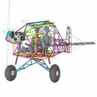
Head in the clouds Posted January 1, 2016 Author Share Posted January 1, 2016 December 23rd 2015 =- January 1st 2016 Being the festive season break I was hoping to get a lot done on DooMaw but Murphy did his bit instead and my wife and I spent most of it getting over minor injuries from a car smash and all the resulting palaver that goes with it, in terms of insurance estimators, tow trucks, getting her a temporary vehicle and so on. Not much fun at all. In between it all I did get some time on DooMaw and it was enjoyable work, having got past the last of the contortions required for welding in the inside of the fuselage structure, now most of it is making bits separately and welding some of them to the outside of the fuselage, much less tedious than it has been of late. Ten days ago I'd just started making the parts for the control stick and aileron torque tube - see last photo in post #69 above - the three small tubes and one longer one, not shown, form the triangular support for the rear aileron torque tube mount and also part of the progressive failure structure for the seat-back. Those four tubes should be the last bits that needed welding to the internal part of the the fuselage, so I got on with those first to get them out of the way. Then I had to add three flat plates to attach the HDPE triangular torque tube support, and tack them in place without harming the easy-melt HDPE. A bit of thin PTFE sheet for insulation and fast tacking and I got away with it, just. Then could fit the front torque tube mount that carries the split square block which resolves all the thrust loads from the elevator push-rods. The front mount needed some delicate welding procedure and order to keep everything aligned but it did end up pulling so that I needed a 0.020"/0.5mm shim under the front two bolts, which irked me a bit. Making those blocks has been a bit of a trial as I got rid of my large milling machine a while ago intending to replace it with a much smaller one but haven't found what I'm after yet, so have had to make those parts with a pillar drill and flap disks. Not very professional but they came out well enough and accurate, so it was annoying that I underestimated the welding pull and needed to adjust them. In the end I decided it was time to service the linisher, all of it's bearings and the drive belt died some years ago, so I spent a day on it and found the required parts and that meant I could linish half a millimetre off the bottom of the block at the required angle and avoid the shim, so I was happy again. And the control torque tube runs smoothly in it's two bearing blocks. Next I set up the tube to add the cheek plates which carry the pair of bearings which attach the joystick, they needed to be very accurately aligned so that the elevator pushrod runs centrally down the middle of the torque tube, so I jigged it simply in steel V blocks and with the bottom edges of the cheek plates on a pair of parallels. Next I added the thrust washers, stitch-welded to the torque tube to avoid distortion and aligned by using a split sleeve of the torque-tube material held in place with a hose clamp, to back it up while tacking it in place. I had to split the sleeve into two to tack the second thrust plate, so that I could remove the sleeves afterwards. Last I added the brackets for the adjustable control stops on the top and bottom. I made and fitted the flat plate that the HS front spar will bolt to, and also the bent plates that will carry the elevator bellcrank. Then I started to make the hardware for the elevator bellcrank and pushrods. I needed bent clevis plates to weld into the ends of 3/4 tubing that will form the arms of the bellcrank, and the elevator control horn. A ball rod-end will fit between the clevis plates. I've tried making these previously and it's not easy to get the bend in the plate even and to drill the holes after bending and welding the plate in, but that's the only way to get the holes properly aligned. So this time I decided to make a simple press-tool to make them. I measured and marked out the plates carefully and cut and drilled them first. Then made the press-tool to fit into a 6 tonne toy shop press, and it worked a treat. It took a bit of careful consideration to line up the top and bottom press-tools accurately enough and the plates didn't fold fully parallel but a little extra squeeze in the vise afterwards and some judicious adjustment with a piece of 1/4" silversteel rod and I had three quite closely matching clevises ready to weld into the tube ends. Another 36 hours for the log, making 564hrs so far. 5 Link to comment Share on other sites More sharing options...
biggles Posted January 1, 2016 Share Posted January 1, 2016 Guys - equating what I am doing by repairing /tinkering in my workshop with what HITC is doing by design and construction of an aircraft from scratch to a standard that would support any 'How to do it' manual, is embarrassing! What HITC is doing by both his design and his construction is top-class stuff; those who know their structures analysis will recognise how all his multiple-tube clusters provide force lines through the common point, for instance. And then - he makes it so!. That is no mean feat by the standards of the best welders.. e.g. Barry Manktelow. HITC's reports on this thread ought to become highly-advised reading for anybody interested in building / maintaining a tube-and rag aircraft. Agree Oscar, but then like yourself, makes time to document the more complex aspects of the build into a mini Engineering Design and Fabrication Report. We certainly have some very capable people on this site ..... Bob 2 Link to comment Share on other sites More sharing options...
gareth lacey Posted January 1, 2016 Share Posted January 1, 2016 HITC, as a retired boilermaker /welder your work is pure fabrication porn to me , your methods and fab/welding is perfect ,top marks and your project is looking superb ,cannot wait to see your end result , by the way i am retired and if you need a help with when two sets of hands are needed just holler and will be delighted to help cheers gareth 6 Link to comment Share on other sites More sharing options...
Oscar Posted January 2, 2016 Share Posted January 2, 2016 HITC - that method of putting on the pushrod end brackets is absolutely BRILLIANT. Perhaps it's just my limited experience, but that just seems to me to be the perfect solution: maximises the weld fillet area, keeps the tube from radial distortion and seals it, all in one hit. I've made up quite a few using the 'two slotted cheeks' method and never been entirely happy about it because any twisting moment obviously puts stress into the brittle grain at the edges of the fillet ( unless the thing is heat-treated, anyway), and even with the smallest TIG nozzle I couldn't get a decent inside run on the cheeks. The elegance of that idea really tickles my fancy. Do you put a little raw linseed oil or a vpi medium into your sealed tubes? I am pretty sure that Howie Hughes didn't do any of that on the early Lightwings, and some of them suffered considerable corrosion as a result, though I think he may have done something with the later ones. 1 2 Link to comment Share on other sites More sharing options...
Head in the clouds Posted January 2, 2016 Author Share Posted January 2, 2016 HITC - that method of putting on the pushrod end brackets is absolutely BRILLIANT. Perhaps it's just my limited experience, but that just seems to me to be the perfect solution: maximises the weld fillet area, keeps the tube from radial distortion and seals it, all in one hit. I've made up quite a few using the 'two slotted cheeks' method and never been entirely happy about it because any twisting moment obviously puts stress into the brittle grain at the edges of the fillet ( unless the thing is heat-treated, anyway), and even with the smallest TIG nozzle I couldn't get a decent inside run on the cheeks. The elegance of that idea really tickles my fancy.Do you put a little raw linseed oil or a vpi medium into your sealed tubes? I am pretty sure that Howie Hughes didn't do any of that on the early Lightwings, and some of them suffered considerable corrosion as a result, though I think he may have done something with the later ones. Ah, thank you again kind sir, but I don't think I can take credit for the design of the clevis ends. I've been making them like that for a long while but it wasn't an original idea. I must have seen it somewhere years ago, most likely on a glider, or some production tube and rag machine, maybe Cubs or Bellancas do it like that. I agree, though, it's a very elegant solution, and easy to run the weld around the outside without ever having to try and get a weld inside the clevis plates. I know Oscar will know this but one tip for those new to welding, that I didn't photograph while welding those plates in last evening, is to have a spacer the same width as the rod end between the clevis plates and an expendable bolt clamping the clevis against the spacer, so that after it's welded the side plates of the clevis are still nice and parallel and with the bolt holes aligned, otherwise the welding will pull it out of shape again. About the linseed oil or Boeing anti-corrosion product ... well I've never really known whether it's necessary or not, but am well aware of the internal corrosion problems that some types have had. Consequently I put the question to those many knowledgeable people on that 'other homebuilding site' to see what they had to say. On there, there are many aircraft maintainers and repairers with plenty of experience repairing damaged tube and rag aircraft, so they get to see the inside of the tubes of aircraft of various ages and types, and presumably are the best knowledge on the subject. What came out of it was that of course there's no harm in doing it, but to do it properly we're looking at around 3kg of additional weight, which is significant so we want to be sure it's needed. The long and short of it is that if the aircraft are MIG welded, as many/most production aircraft are, then it's essential because pressure testing of MIG welded tubes tended to show that they were rarely properly sealed, the main reason being that with MIG production they tend to keep the weld amps as low as possible and rely on a larger fillet and good 'to the node/avoiding moment connections' design to prevent blow-throughs during the welding process. The consequence of that is occasional poor penetration and weld overhangs which conceal unsealed sectors of the weld, and hence 'breathing' of the tube interior with every daily temperature change. In a coastal environment that very rapidly leads to internal corrosion. TIG and OA welded structures, if done carefully, tended to be fully sealed and showed no signs of corrosion in even very old airframes. So, DooMaw being a TIG welded airframe, and me being a bit pedantic about the welds, no I haven't injected any fluids into the tubing. Also - not familiar with the term 'vpi medium', is this some kind of self vaporising thing that might be lighter? I'm certainly not averse to injecting something before welding up all the 1/16 breather holes in the tubes. HITC, as a retired boilermaker /welder your work is pure fabrication porn to me , your methods and fab/welding is perfect ,top marks and your project is looking superb ,cannot wait to see your end result , by the way i am retired and if you need a help with when two sets of hands are needed just holler and will be delighted to helpcheers gareth Thanks Gareth, the offer is much appreciated, as is that of Geoff a while back. I'll certainly keep them in mind as there will be a great benefit to having more hands to help when it comes to the wings and rigging stages. I could have done with some help making parts too, but have never got ahead enough with the design work to have parts and materials waiting to be made, I was too keen to get out from behind the computer and into the workshop. It won't be long before I'll be making the engine mounting and having to dangle the engine in place for tacking that up, so would appreciate some extra hands then too, if you have the time? Perhaps PM me your phone number and/or email and we'll keep in touch about it? Thanks! 1 1 Link to comment Share on other sites More sharing options...
Oscar Posted January 2, 2016 Share Posted January 2, 2016 HITC: Wow, someone else who has had the 'just do the last bit of welding on the tube', and had the air pressure repeatedly blow out the last bit of the weld run. First noticed that 30 years ago, when doing suspension tubes for my racing cars using nickel bronze brazing!. We impecunious lads doing back-yard race-car building used N-B bronze brazing for everything for our space-frame cars, and almost never had any structural failures - once we had learned to design the joins intelligently and run the braze properly with the right carburising flame. It was 'local' knowledge, passed from successful builder onwards.. Yes, a fully-sealed tube cannot gain moisture and therefore corrosion stabilises. The old linseed oil method, if heated and properly distributed by running around the tubes by rolling the structure, coats the inside of the tubes - including any scale produced as a result of the welding process - in a water-impermeable layer of 'varnish'. You can do that by adding a small amount of linseed oil into each tubs, spotting the breather hole shut, and heating the tube/s with a hot-air gun while positioning the structure in a series of 'revolving' attitudes so the majority of the liquid linseed oil runs down the tubes to the weld join positions. If this sounds like a bit of a 'bush mechanic' solution, you might like to check with some aero-engineers.. VPI is 'Vapour-Phase Inhibitors': anti-corrosion mediums that infuse throughout a structure as, basically, a gas. You might find a visit to the Cortec site interesting: http://www.cortecvci.com/Products/products.php?showonly=MetalWork and choose your solution. There is a Cortec VCi-326 inhibiting oil sold by Aircraft Spruce (Pilots Shop in Aus.) that might be worth considering for a fully-sealed tube as an additional protector. VPI's sound like a snake-oil solution - it's not.. Nearly 30 years ago, I tried some Cortec 'anti-corrosion stick-on pads' for my own interest, inside a box of various spares I carried on my yacht, that was moored on Pittwater: salt water. In a large pressed-steel cigar tin, I had a mix of stainless steel bolts, nuts and washers, monel and aluminium rivets and some mild steel screws and split-pins. Everything in that box was corrosion-free after more than five years. Some other fittings on the yacht, where the Duralac had not prevented electrolysis due to inadequate attention to detail of its application, were shot. I sincerely believe in the utility of Cortec products provided they are used intelligently. 2 Link to comment Share on other sites More sharing options...
Head in the clouds Posted January 5, 2016 Author Share Posted January 5, 2016 Jan 2nd - Jan 5th 2016 A bit of time spent welding in the parts I made previously, shown in post #81, then it was back to making more parts. This time it was brackets, and rather tricky ones at that. I've been giving thought to them for some while because I couldn't think of an easier way of achieving what I need, i.e. easy removal of the entire tail-feathers if that should ever be required. On the surface the brackets look simple enough. However, since they don't have any available adjustment, and when they're bolted up they determine the alignment of the horizontal stabiliser, they have to be made and installed absolutely accurately. All the other bent brackets on the fuselage have been quite simple and not overly critical so I was able to just clamp them to the edge of a part of the workbench where I have provided it with a gently radiused corner, and judiciously fold the plate with taps of a hammer, back and forth over the length of the bend to prevent stretching the metal and making an inadvertently curved plate. The CAD screenshots below show four brackets in grey colour holding the front and rear tubular spars of the HS. There is a vertical bracket with two vertical folds in it and three curved brackets like the saddle clamps that are used to hold electrical conduits to walls, or plumbing pipes to masonry. Unfortunately I couldn't use those kind of commercial items because they're generally made from cheap material rather than chromoly, and in any case you'd never find one to fit exactly - The brackets are made from 1.6mm/.063" chromoly sheet and it's quite a hard material to bend without the proper machinery. If I had a brake press or sheet-metal folder I could make the vertical bracket easily enough, but I haven't, and I didn't want to go to a metalwork shop for single items, it's far too time consuming (well ... so is making the tooling yourself ... but anyway) and it's far more satisfying to have made anything you can on the project, than to have it made for you. So .... I made myself a tiny version of a brake press to use in my toy 6T shop press, and it worked a treat. It's only 100mm long but will also serve to make lots of upcoming brackets I'll need while making the wings. Below are pics of the little brake press, and the vertical bracket I made with it - Emboldened by the success of that I had a think about how my old mate Bazza the toolmaker would go about making a press-tool to make the saddle clamps. At first I imagined making the main curved part in one pressing action and then having a second forming tool to make the return bends but I couldn't think how to make them accurate and consistent. Then it occurred to me that every press-tool that Bazza made did the entire job in one action. Some of his tools used to shear and press very complex shapes in one action, straight from sheet material fed into it. I recalled that his watch-word was 'control'. Every part of the tool must prevent the material from going anyway it shouldn't go. If you were folding a part, the material just beyond or behind the fold would always want to react outwards as you folded it, so you needed something pressing against that area, resisting that reaction, and that support had to remain throughout the pressing process until the shape was complete. That often meant having parts sliding against each other as the top and bottom tools closed into each other. Armed with that knowledge the tool design for this became relatively simple, and would have been simpler still if I'd had a milling machine to make it with, but I had to settle with fabricating all the bits and welding them together and a bit of flap disk relieving of them at the end. It took a day and a half, a bit expensive in time for a small step forward on the project, but the main thing is they came out very accurate so I am happy with them - Another 37 hrs - a total of 601 hrs so far. 3 1 Link to comment Share on other sites More sharing options...
pylon500 Posted January 6, 2016 Share Posted January 6, 2016 G'Day HITC, Afraid to say I haven't been watching too closely (being a sheet metal builder), although I must compliment you on your welding work. I'm terrible, hence I built with sheet and rivets. While trolling through the photo's and CAD images, I had a look at your elevator/horn connection, and was thinking, 'Going to have to put an anchor nut inside the elevator, or have some form of access to do up the nut?!' Not sure how often you want to take off the elevators (not a lot I imagine), but had the thought of attaching via 'cuff' either end of the horn, and just slot in the elevators on assembly. Have photoshopped your image below; In hindsight, probably should have depicted in a slightly different colour to highlight. Just a thought..... 1 1 Link to comment Share on other sites More sharing options...
Head in the clouds Posted January 6, 2016 Author Share Posted January 6, 2016 Hi Pylon, G'Day HITC,Afraid to say I haven't been watching too closely (being a sheet metal builder), although I must compliment you on your welding work. I'm terrible, hence I built with sheet and rivets. While trolling through the photo's and CAD images, I had a look at your elevator/horn connection, and was thinking, 'Going to have to put an anchor nut inside the elevator, or have some form of access to do up the nut?!' Not sure how often you want to take off the elevators (not a lot I imagine), but had the thought of attaching via 'cuff' either end of the horn, and just slot in the elevators on assembly. Have photoshopped your image below; [ATTACH=full]40567[/ATTACH] In hindsight, probably should have depicted in a slightly different colour to highlight. Just a thought..... I'm sorry but I can't actually see what you've photoshopped. I do appreciate the input though, and your compliment, thanks. This is actually a screenshot of the CAD model before it had a bit of modification in that area because as you noticed, the access to the hinge bolts is a bit limited and the nuts also would clash with the saddle clamp so they've been changed to cotter pins and the hinge sections shortened a little to provide clearance. I'm not sure how obvious it is from the image but the centre section is quite separate from the HS each side because the HS folds up at the red hinges. Also, there is a fairing that covers the top of the HS centre section and extends up to the underside of the fin, it is removable for inspection and maintenance, so access in that area is better than it at first appears. Ahhhh - I've just seen what you're referring to, and your 'cuff' suggestion. It's a good thought but the 'nutless bolt' you refer to is actually a fixed pin (or it may end up fixed but sprung) that auto-disconnects and auto-connects when the HS is folded upwards prior to folding the wings, which might happen on a daily basis, so there's no nut involved. Thanks for keeping a watchful eye out for me though! 1 Link to comment Share on other sites More sharing options...
pylon500 Posted January 6, 2016 Share Posted January 6, 2016 Actually, I had been wondering if there was going to be a folding tail with the amount of work there? Why not just add a hinge between the elevator horn arm and the elevator? It's getting late, so I've only 'shopped one side. Could also use an eyebolt into a couple of tabs.. 1 1 1 Link to comment Share on other sites More sharing options...
Head in the clouds Posted January 6, 2016 Author Share Posted January 6, 2016 Actually, I had been wondering if there was going to be a folding tail with the amount of work there?Why not just add a hinge between the elevator horn arm and the elevator? [ATTACH=full]40569[/ATTACH] It's getting late, so I've only 'shopped one side. Could also use an eyebolt into a couple of tabs.. Excellent thought pylon! I haven't been entirely happy with the detente pin method as you'd have to be certain the pin was engaged after folding/unfolding so it's not foolproof. Your hinge method is foolproof because it doesn't need to be disconnected to fold the tail. Thanks for the input, much appreciated, the 'pylon500 hinge' it will be! 2 Link to comment Share on other sites More sharing options...
Head in the clouds Posted January 25, 2016 Author Share Posted January 25, 2016 I've had to spend a fair while back on the CAD work again, this time designing the adjustable pedals system and modelling all the components for it. I need to have adjustable pedals because the seat can't move due to its being a part of the progressive collapsible structure which is part of the crashworthiness design. Also, since the whole seating area is part of the ergonomic design for crashworthiness and flail clearances, it's desirable to not use much in the way of seat cushions to adjust the body position, so the pedals really must have quite a lot of movement available to accommodate as large and as small crew as possible. As far as adjustable pedals go, there aren't many good ones unless they're quite complicated. Simple ones either just move the pedal bar back and forth leaving the cable/pushrod connection and hinge point unchanged, or they rotate the pedal forward and backward around the hinge point, also leaving the cable/pushrod connection unchanged, or they rotate the pedal forwards and back and have a series of connection points for the cable to the pedal. None of these methods is very attractive because they all only have one position where the pedal geometry is ideal. In all other positions as you press it the pedal either moves up from the neutral position, or down from the neutral position, instead of just moving forwards and backwards. And - the further you adjust the pedal fore or aft, the worse that geometry becomes. Given that DooMaw's pedals must have a large adjustment range it meant that I have to use a rather more complex pedals arrangement to achieve that while also having good geometry at all pedal positions. The system that I most favour for its relative simplicity and reasonable lightness is the static cable and 'S' tube adjustment as used in many gliders. For DooMaw the cable connection method from each crew position has to be somewhat modified to suit the side-by-side seating compared with the usual tandem seating arrangement of gliders. A further modification is the addition of toe brakes and brake cylinders, whereas gliders usually have a single handbrake lever. This pedal arrangement has been adapted for use in various powered homebuilt aircraft, for those not familiar with it here is an image showing the method - Back on the geometry bandwagon - DooMaw being a STOL where use of brakes plays a large part in managing the aircraft in ground handling, I want the brakes to be very user-friendly. On the ground when a pedal is fully depressed is the time when you are most likely to be either needing to use the brakes differentially, maybe to help prevent a groundloop, or perhaps just wanting to do so to turn around in a tight space. Similarly you don't want to be pressing on the opposite brake at such a time. Consequently I spent a lot of time playing around with the geometry of the brake pedal (the small pedal hinged on top of the rudder pedal) and it's connection position in relation to the position of the brake cylinder, adjusting them until the brake pedal stays upright or actually moves forward a little when that rudder pedal was fully depressed, and the brake pedal moves away when the rudder pedal is fully back. That way there will be a tendency for the foot to come onto the brake pedal automatically as the rudder pedal is pressed further, and on the other side the brake pedal has moved out of the way to reduce the likelihood of touching that brake when it definitely wouldn't be wanted. The image below might be easier to follow than the description - Having got the geometry right I could set about making all the parts - who would think there are so many parts in just the pedals ... and that's not all of them, I still have to model and make the release mechanisms, the handles that you use to pull and push the pedal sets, the cable attachments to the firewall, quite a number of pulley mounts and cable guides and the underfloor stiffener plates, since the pedal sets are bolted direct to the plywood floors, not to the steel airframe. Anyway, I'm tired of making parts for now so I'll get back to welding and assemble this lot first, and make the rest of the parts later. 51 hours in that lot, making a total of 652 hours so far - CAD time not counted ... 5 1 Link to comment Share on other sites More sharing options...
Oscar Posted January 26, 2016 Share Posted January 26, 2016 HITC - as usual, construction porn; those toe brake pedals are verging on adults-only viewing... The pull-back cable for adjusting the position of the pedals is very 'standard glider'; have you worked out how to secure in position? I ask, because I had an 'interesting' experience with just such a system years ago. Glasflugel Hornet, my familiarisation flight. I am not exactly sure of the mechanics, but suffice it to say that the pull-cable first disengaged some sort of detente pin and then allowed the pedals to be pulled back to suit the customer. All of that flight was 'interesting', and I won't go into the rest of it, but since I was to take it for a 300k attempt next day, I decided on approach to see just how short I could get it in. Allowed myself 50 feet or so over the fence, pulled full brakes ( actually, 90-degree flap position) - which were so powerful that pushing the nose down to keep the speed up, caused my sandwiches to fall forward from the parcel shelf and hurtle past me on the way to the nose. I caught them, but in so doing, wriggled slightly loose in the harness, which allowed me to come forward a wee bit, against which I braced my feet on the pedals - as one does instinctively. Obviously, I had not managed to fully engage the position detente pin in the holes in the position rack - and the rudder balance spring(s) pulled the pedals fully forward and way out of my leg reach (being Cherman, the Hornet was no doubt built for large buggers). So: no rudder... and the rudder adjustment handle was designed to be used BEFORE one strapped in, and not reachable from the supine seating position when strapped in, even if I'd hand a spare hand apart from the one holding the stick and applying secondary effects of ailerons to get me around the sod who had, without looking, decided to drag his landed glider across the strip right where I needed to round-out and the hand playing the flap/brake handle to get me some more room. The Hornet's owner ( and CFI of the operation) was not best pleased with my wobbly-appearing landing, since this was his personal racing machine, but when I explained the circumstances ( and since I hadn't bent it..) he was somewhat mollified. 'Yes, that can happen, you need to really test the rudder pedal security before you take off' was his comment, so I imagine this was not the first time the pedals had made a break for freedom. 2 1 Link to comment Share on other sites More sharing options...
Head in the clouds Posted January 26, 2016 Author Share Posted January 26, 2016 Nice story, Oscar, highlighting exactly the way things go progressively pear-shaped, if just a couple more 'factors' had come into play the outcome might not have been so good. Nicely done keeping the main occupation (flying the plane) a priority! That scenario is rather too similar for comfort to the one where the pilot seat in Cessna singles doesn't latch in place properly and the seat slides back on 'rotate', tempting the pilot to use the yoke to haul himself forward again ... it happened to me in my own C172 even though I used to wriggle and bump myself around in the seat to check the latching. Gladly I had been made so aware of the danger that when it slid back I just let go the yoke and then used the edge of the top of the panel to pull myself forward again - and in a climb even that's no easy feat. Yes, I'd had a good look at the latching arrangement for the pedals for DooMaw and I will use a similar detente pin but it has deep engagement into holes in the guide tube. It will be lifted by a push-pull lever (rather than a pull-only cable). The lever will be lifted to disengage the pin and then pulled or pushed to move the pedals. Once the pedals are adjusted the lever will be locked down again under a spring latch so it (and the detente pin) can't be accidentally disengaged. Also, my pedal balance springs will resolve to the sliding mechanism itself (they'll be recoil/clock-spring style wound around the pedal pivot tube) rather than to the fixed part of the airframe, so they won't tend to pull the pedals forward while they are unlatched. So many traps for the wary, let alone the unwary, aren't there? 1 1 Link to comment Share on other sites More sharing options...
Oscar Posted January 26, 2016 Share Posted January 26, 2016 Absolutely agree - the separate latching mechanism is the way to go. One does the 'full and free' controls check AFTER setting the pedal position (in a glider - you can't reach forward down the cockpit feet tunnel with your hand to check it), and I'd done that, but that hadn't included load on BOTH pedals simultaneously. Possibly, the lateral load from one pedal applying load only had allowed the pedal mechanism to rock and wedge before full load came on the detente pin... Having a separate latching mechanism allows you to 'rock' the pull load against the feet load and get the locking handle down to its correct position - I like that notion. If I may be allowed an observation - and ABSOLUTELY not meant as any sort of 'patronising' comment, because I genuinely appreciate the thought that goes into 'doing things correctly', it seems to me that everything you are doing is backgrounded by having looked at, analysed, and extracted whatever lessons there are to be learned from exposure to numerous examples of good and bad practice. Since just about everything I understand about aircraft design has come from exactly that process with the explanations passed on by a family member whose living has mostly been made from correcting design f%ck-ups, it's really inspiring to see someone conscientiously avoiding those problems rather than designing them in... 1 1 Link to comment Share on other sites More sharing options...
Head in the clouds Posted January 26, 2016 Author Share Posted January 26, 2016 ... it seems to me that everything you are doing is backgrounded by having looked at, analysed, and extracted whatever lessons there are to be learned from exposure to numerous examples of good and bad practice. ..... to see someone conscientiously avoiding those problems rather than designing them in... Aaah, yes definitely. I really enjoy design work and I usually try and design things using original concepts but there really isn't much out there that hasn't been done before, and mostly has been done numerous times. Consequently a lot of my 'original design' is very much influenced by what I've seen when my natural inquisitiveness has had me delving head-down into the 'workings' of things. Naturally, after a while you start to recognise good practice and bad practice and I just try and copy the good stuff and stay aware and wary of the bad stuff. I also seem to have a natural tendency to foresee things that might go wrong I'm also paranoid ... But, most of all I had the benefit of years working with the truly amazing engineer and my late great mate Barry Hughes, who taught me so much about what works and what doesn't - if you ever doubt your design just ask yourself "would the Germans do it that way?" Link to comment Share on other sites More sharing options...
Oscar Posted January 26, 2016 Share Posted January 26, 2016 But, most of all I had the benefit of years working with the truly amazing engineer and my late great mate Barry Hughes, who taught me so much about what works and what doesn't - if you ever doubt your design just ask yourself "would the Germans do it that way?" And - if the answer is 'YES', then you look for a simpler way...... and if the answer is 'no, but Citroen would', then you go have a stiff drink and start again from scratch.. 1 1 Link to comment Share on other sites More sharing options...
Marty_d Posted January 26, 2016 Share Posted January 26, 2016 ...and if the answer is "no, but the English would", then you give up and buy one from the Germans. 2 Link to comment Share on other sites More sharing options...
Recommended Posts
Create an account or sign in to comment
You need to be a member in order to leave a comment
Create an account
Sign up for a new account in our community. It's easy!
Register a new accountSign in
Already have an account? Sign in here.
Sign In Now