pylon500
-
Posts
1,412 -
Joined
-
Last visited
-
Days Won
9
Content Type
Profiles
Forums
Gallery
Downloads
Blogs
Events
Store
Aircraft
Resources
Tutorials
Articles
Classifieds
Movies
Books
Community Map
Quizzes
Videos Directory
Everything posted by pylon500
-
 If Taree council is anything to go on, I wouldn't be holding my breath.... There is land around Taree airport that could be developed, Like my site, but the owners of the various lands have not had much luck in trying to rezone or modify usage, so nothing has happened there. On top of that, the council then decided to develop more hangar space on the airport, and fix various problems with drainage and levels. I hear the works cost somewhere around the $2.5m, has around 10 sites available but all are priced as mentioned above, as commercial sites, even though many locals have determined that the sites are not really big enough to be effectively commercial; http://www.aircraftkits.com.au/documents/Taree%20Report%20May2015.pdf Add to that the fact that the earthworks did little to help the drainage problems, and you begin to wonder if councils have any form of competence...?
 -
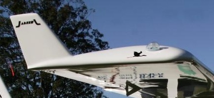
Unfortunately, I doubt that the winglets fitted to the jabiru's do anything useful at all... They are too thick, have the wrong section, and have been fitted to a wingtip that is already using a totally different aerodynamic technology, ie; turned down Hoerner style tip.

-
It just gives you that numb feeling all over, like, how much of this can we take?
-
Live prop nearly kills a pilot
pylon500 replied to rick morawski's topic in AUS/NZ General Discussion
Welcome to impulse magneto's... -
And being a control zone, all us ultralight people will have to drive in....
-
Plane spotting on steroids
pylon500 replied to rankamateur's topic in Aircraft Incidents and Accidents
I can just imagine CASA granting someone an AOC to fly into here....... NOT! -
Yes, often an 'inflow' straightener is used to sort out any turbulence generated from the intake to the fan, to give the fan 'clean' air to run in. This is often a problem with pushers, the aeroplane flies in clean air, but the prop gets dirty air, which is noticed as 'noise' from pushers.
-
All power to the students, and the state, which no doubt put up the cash for materials. But, and there's always a but, two things I noticed; Looking at the way it's flying in the video, and as has been said above, I think it's using all the power it's got, and it's not really zooming around the sky? (This from an aeromodellers perspective) Not sure if it would get off the ground with two people in it...? The other thing I noticed, which may go some way to curing the first observation, is that they are using a multi-blade fan, as you do, but don't appear to have a flow straightener after the fan? A propellor relies on having as much diameter as possible, thereby becoming a wing travelling through the air generating forward lift (or deflecting thrust backward for the non Brunellians') but only creating a minor amount of swirl around the fuselage. A smaller, faster turning fan needs more blades to absorb the power, but in so doing induces a fair amount of swirl down the tail pipe, losing direct velocity and making the tail pipe appear longer. A flow straightener will redirect the flow directly aft, adding to thrust.
-
DooMaw - building a STOL
pylon500 replied to Head in the clouds's topic in Aircraft Building and Design Discussion
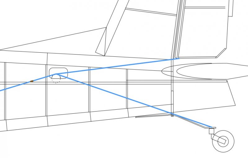
Yes, very fiddly little build.. Had a similar problem on my Stollite, having the rudder on top of the fuselage and tailwheel below. Solved mine by splicing the cable, but then running all four cables over four pulleys to maintain tensions, yes, springs at the tailwheel attach; Not really as easy as it looks because of the cables following the taper of the fuse requiring the pulleys to be at slight angles. (Thought I had a photo inside the fuse?)
-
You remember that one? That followed on from an earlier concept; Even started some drawings for it; Only got a few bits made..... Too many projects....
-
As you say, from a technical standpoint, 400 odd horse power to do around 150 knots, yeah, not efficient. But as someone else pointed out, we're only flying ultralights for fun, just imagine the looks when you roll up in something like this !!! And for my next project;
-
DooMaw - building a STOL
pylon500 replied to Head in the clouds's topic in Aircraft Building and Design Discussion
G'Day HITC, Don't panic, but I have the following for you to consider; Just looking at your elevator linkages and realised you've had to go the 'lessor' way of having a 'push for up' tube, instead of the preferred 'PULL for up' system. I know various others have gone this way as well, Lightwing and Foxbat to name a couple, but they have made up for it in different ways... Lightwing uses a fairly large diameter tube with the thinnest wall they could get, while Foxbat use two shorter tubes via an idler. The problem stems from the possibility of flex in the push tube that could induce further travel under G load, or in an extreme case, failure of the tube in bending while under the compression load of movement when subject to G load induced by said movement. While this may seem a bit of a stretch as a failure mode, consider; A STOL approach with full flap, stick already half way back to compensate pitching moment of flaps (ie compression load on tube), an unexpected downdraft requiring a sudden application of full elevator, elevator hits it's movement stops, further application at the stick adds higher compression load to tube, a moderate to heavy touchdown (momentary 5~8G impact not impossible), elevator tube now 5~8 times heavier causing it to flex out of alignment, added to the existing compression load already applied, the tube buckles to the bottom of the fuselage thus changing it's original length. This all took half a second. Now the aircraft rebounds into the air, the flaps start a pitch-over movement, added to a quick fore/aft movement of the stick to try and correct the bounce but because the elevator tube is now a little shorter, the pitch-over is exaggerated, another more violent and stronger back stick is applied, but instead of getting up elevator, the tube fails and the aircraft is nose down, low and with no pitch control !! It could be said that a similar problem could stem from having a 'pull-up' tube when G load is applied, where flex would shorten the tube thereby inducing more pull and hence higher G! Granted, but the tube will not flex as much when under a tensile load as opposed to a compressive load. Still, all you need to do to protect from the above is support the tube so that it can't flex out of alignment, either with a swinging cable, or as it looks with an 'under' pivot point at the stick end , and an 'over' pivot at the elevator end, there should be a neutral point somewhere along the tube where there is no vertical movement, and you could fit a roller or some sort of guide to maintain alignment. I remember the Pilatus B4 used felt guides for the elevator push tubes where it passed through the various bulkheads. Did tend to squeak when they got dry.... Sorry if I haven't made these comments earlier. -
There is another one out there, that has also flown, here's one of the test flights; And if you browser can translate Russian, here's some of the build forum (Russian EAA); http://www.reaa.ru/cgi-bin/yabb/YaBB.pl?num=1287751367/0 Corvette V8 driving two fans..... not quite RAAus
-
I think you can class a ducted fan as a propellor....? Hope so, cause I've got a few ideas... "Wing area; 8.5m² (23.6 sq ft)" ?, more like 91.4 sq ft I tend to agree, probably more like 20 Lph. With a 1000cc bike engine, it's probably only just putting enough thrust to get airborne with two people in it, but if you've got the money, you could put the Subsonex motor in it (and VH rego).
-
Some more info here; http://www.gonzoaviation.com/clanok/projekt-ul-39
-
Ahh, but do they get to live on the typical Ozzy/Kiwi, quarter acre block...?
-
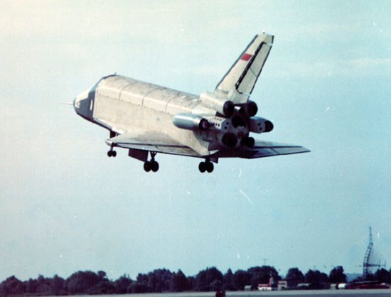
?, I hadn't heard this, and looking at the videos of the landing I'm trying to figure out how it did a 'go round' without the previously removed jet engines in place? Yes, it started with jets fitted to it, and all test flying was done just like an aeroplane, circuits and all, but when finally launched (unmanned) to orbit, the jets had been removed..
-
Plane crashes at Redcliffe in North Brisbane
pylon500 replied to ZeroAlpha's topic in Aircraft Incidents and Accidents
Not sure about instructors and free beers (and it's not just that I'm a non drinker), but any bad flying by a student/early solo, really has to be some sort of reflection on the instructors abilities. Yes, I take some of the blame for a student wrecking my Lightwing.... -
Remember the forum rules; No pictures, then it never really happened........
-
Plane crashes at Redcliffe in North Brisbane
pylon500 replied to ZeroAlpha's topic in Aircraft Incidents and Accidents
And to think neither of these were real aeroplanes (taildraggers), and they still could land them?! I guess some people just shouldn't fly (themselves). -
"Missed a Darwin Award by that much!" (Said in a Maxwell Smart voice.....)
-
Has anyone built one of these yet {lol}
pylon500 replied to Narrabeenrick's topic in Aircraft General Discussion
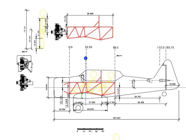
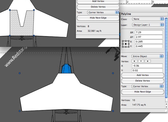
Just fed the drawing into my CAD program, remember the top of the fuselage on this is also part of the main wing, which appears to have around 147.7 sq ft (13.7sqm) of area, which is way over the maximum required 10 sq m for 95:10, and if you add the lower wing which is another 32.9 sq ft (3.0sqm), this is easily a 95:10 aircraft.
-
Has anyone built one of these yet {lol}
pylon500 replied to Narrabeenrick's topic in Aircraft General Discussion
Really? You've only got to look at the way it flies to see it's only an ultralight. 300kg gross weight with a 503, and remember, you can count the area of the lower biplane wing (inside the fuse), so it probably complies with 95:10! And could easily be built into 101:55/19-xxxx. -
Was trolling around youtube looking at some of the latest ideas in flying cars and found this; Looks like it got developed and produced even further than the Molt Taylor Aerocar, but got killed by bureaucracy.
-
DooMaw - building a STOL
pylon500 replied to Head in the clouds's topic in Aircraft Building and Design Discussion
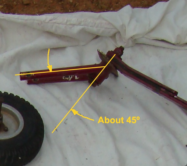
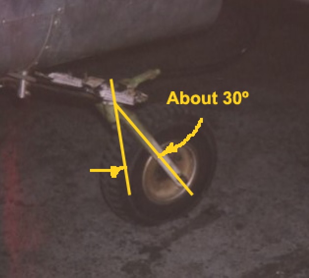
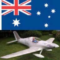
G'Day HITC, been following the thread off and on and must say I love your manufacturing skills an attention to detail. Having said that, I now and then spot something which, from an outside perspective, I have a little head scratch about but is usually solved by reading the text a little more closely. However, I spotted the detail for your tail wheel drawing as well as the photo of your proposed plastic tailwheel, and feel I should comment again... Being an avid tailwheel driver, I do find people thinking of tailwheels as 'just the little wheel down the back', and then running into problems with them. Obviously when you think about it, a tailwheel is equally important as a nosewheel, as it does the same job, so all it's load factors and dynamics need to be considered as closely as is a nosewheel. To start with, I wouldn't trust the plastic tailwheel hub as far as I could throw it, with or without good roller bearings. While the moment arm of a tailwheel will give it better leverage over the mass of an aircraft compared moment arm/side loads imposed on a nosewheel, the side loads are still significant to be imposed on a plastic hub. I know many use them and get away with it, but I get the impression the 'DooMaw' is being aimed into the STOL/Bushplane operation so robustness is somewhat of a requirement. My other concern is the layout of your tailwheel fork hinge line dynamic. I see these serious 'aft' trail tailwheel on a regular basis, and always question their use...? When asked, designers using them tell me that having a lot of 'trail' in a tailwheel helps keep the plane straight, supposedly by resisting any sideload !? While this sounds about right, what really happens is these tailwheel will happily follow wherever the fuselage is going, unfortunately if there's a crosswind or the aircraft has decided to head off into a ground loop, then the sideloads on this type of layout make it nearly impossible to stop a ground loop without the use of brakes. I find the reality is, these aircraft are usually hard to turn when taxying, being very heavy on the pedals and usually requiring the use of brakes to assist turning. I am also sometimes told long trail tailwheel are less susceptible to shimmy, but I don't believe that, only that the shimmy frequency is lower (but just as damaging). My own 'Stollite' (https://picasaweb.google.com/113292981019876413104/BuildingAndFlyingTheStollite#) uses a modified Lightwing tailwheel where I reduced the amount of trail, and it is very easy to taxi in strong crosswinds without the use of much brake, which is just as well as the brakes (cable operated) are not the best. The pictures show (sort of) the difference in rake or trail in the forks, between a standard Lightwing (red) and the modified (white) forks as used on my Stollite. Sorry for the long winded description of what most people think is a simple item.