pylon500
-
Posts
1,412 -
Joined
-
Last visited
-
Days Won
9
Content Type
Profiles
Forums
Gallery
Downloads
Blogs
Events
Store
Aircraft
Resources
Tutorials
Articles
Classifieds
Movies
Books
Community Map
Quizzes
Videos Directory
Everything posted by pylon500
-

CLEKO give, buy, swap and sell place
pylon500 replied to eightyknots's topic in Aircraft Building and Design Discussion
Actually, I, pylon500 and two mates are embarking on a new project(s), and we're gonna need all the cleco's we can get our hands on. If anyone has spare/leftover/finished with cleco's, PM me, and we'll look at some sort of deal.
-
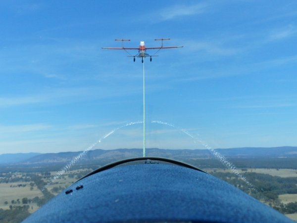
Prop doesn't look like it was developing much power at impact.
-
He was lucky the parachute didn't tangle with the wreckage. While most ultralights have ballistic deploy systems, that will get the chute clear of the aircraft, hang glider just a have a hand deploy, and they have been known to tangle and not deploy fully.
-
Unfortunately there are those that will try to 'DRIVE' Foxbats (and Vixens) onto the ground, much too fast, and there are a few broken nosewheels around the place. Even flapless, a Foxbat should not touch the ground above 45kts, and the nosewheel probably shouldn't touch till below 30kts. This is such an easy aeroplane to land...
-
Thruster?! Nah, it's a Javelin. Another project I'm supposed to finish for a mate (he's in no hurry, got two other planes...)
-
I've just realised that talking about making props is a bit of a thread drift, so I'll leave it there for now, but will post a link to photos of 'One I prepared earlier'; https://get.google.com/albumarchive/113292981019876413104/album/AF1QipO4Yp7-E7wI6rRX5D_BcFVgmQVh_enL5dZJ3e1O
-
With the timing and everything, it really was one of those $hit happens scenarios. Although he did seem really positive about making sure it wasn't his fault...?
-
 WHAT THE ..? Well, there's a back end I never thought I'd see!
 -
Well according to most Skyfox/Gazelle owner/pilots, the RAAus office for one..... I know no one else likes/wants them..
-
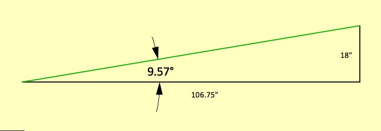
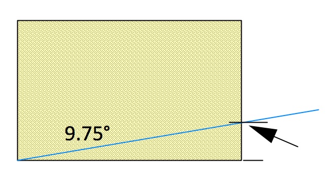
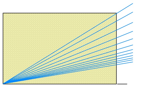
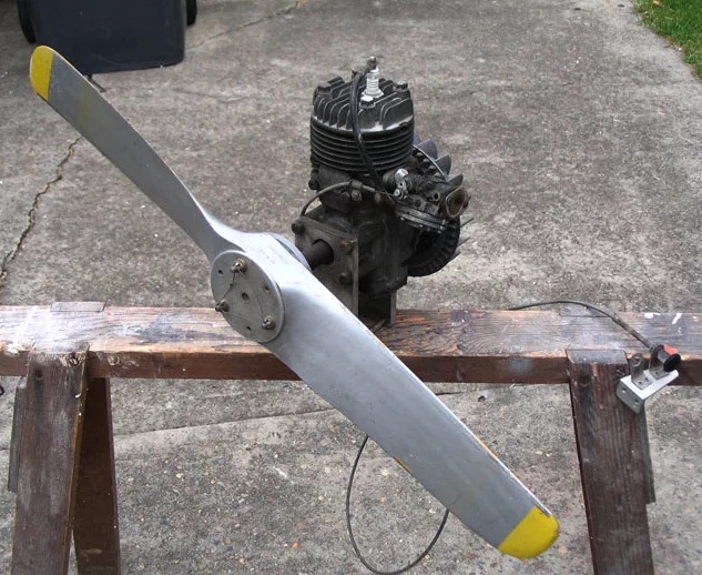
Just guessing at the power output (or lack of it) from the Skylark, and low speed airflow, I would be guessing at something in the 34x18 to 36x22 size range. If you don't actually plan to fly the engine/prop, it doesn't have to be perfect. Calculating, marking and carving a prop isn't as hard as many think, the real 'art' is how to lay out the twist and the planform. Really basic propellors like the Scout prop, the Allsize props on the Skyfoxes or many of the WW1 vintage props, use the same concept and simplicity. (I can hear the Allsize lovers getting angry..) Start with a block of wood, laminated if you want, or just a medium weight hardwood (I wouldn't use common Pine, but a nice straight grained piece of Cypress Pine would be OK), I've used darker coloured Maple or Meranti in single block for short use props. The pitch calculations are not as hard as you might think.. Say an 18" pitch, on a 34" diameter prop. A 34" diameter is (Ø x π) which is 34 x 3.14= 106.75" in circumference. An 18" pitch means we want a triangle 106.75" along the base, and 18" high at one end. Using simple trigonometry (or a calculator) you find the angle at the low end of the triangle, 9.57° Lets assume a piece of wood, 34" long, 2½" thick and 4" wide. Draw a rectangle that represents the end of your piece of wood, 2½" by 4". Using a protractor, draw the line that represents the pitch angle from one bottom corner. Take your 34" long prop blank, figure out which way the motor turns (!), and determine the trailing edge at each end of the block. Mark the height as shown by the arrow, on the LEADING edge of the block. (This layout will give you a SQUARE prop!, if you want it tapered, there's a bit more work...) Repeat all the above calculations and markings for each inch inwards along the blank, remember, one inch in on one blade, is TWO inch less for each diameter calculation. You should end up with; All these lines are the UNDERSIDE of the blade section at each point. When the angle goes out the top corner, stop the marking. If that point is more than say 6" from the centre, you may need a thicker piece of wood. From here on, check various youtubes on how to carve (I've got to go to work..)
-
If you are planning to run direct drive, the old Scout prop would be way too big. I was playing with a couple of Kirby (Tecumseh) 144cc motors back in the beginning, running direct drive props. My last set were 32x16, and could have been maybe a little bigger? Yes, it's a pusher, I was using two of them on a home made trike.
-
Good point! When do we get w_i_d_e s_c_r_e_e_n avatars?
-
I use this gif over on Homebuilt airplanes.com, but it would also lose out if stuck in a round hole. (I'm actually amazed I still had this in my computer somewhere!
-
High wing strut braced... airliner?
pylon500 replied to Gnarly Gnu's topic in Aircraft General Discussion
All the efficiency they gain from the higher aspect ratio wing (which is all it is), will be lost in the biplane interference caused at the strut junction, to say nothing of the section buildup created by the straight strut. NASA, well, I think mainly their students, are coming up with a lot of ideas lately, that don't really make a lot of sense, or miss obvious (counter) explanations that have been known for years. There was a lot of work (and money) spent on trying to prove some nineteenth century bird watchers theories about winglets and like, which I found on youtube; They were trying to prove that a flying wing can be efficient, but really, all it proved was that higher aspect ratio wings are more efficient aerodynamically. Don't get me wrong, I like flying wings, but the compromises involved in getting them as efficient as a 'normal layout', mean dealing with some pretty serious stability problems. It might be OK today what with autonomous artificial stability and stuff, but get it wrong in an airliner, and it'll suddenly turn into a cloud of composite bits and bodies hurtling through the sky.... -
Sorry Ian, don't like it. No need to follow modern trends (they will come back anyway), it's aimed at facebook and related rubbish to show mugshots, half of us have our planes instead. Planes fit in square holes......
-
Nailed it! Strong language warning, don't do this
pylon500 replied to fly_tornado's topic in Student Pilot & Further Learning
With that much wind, he should have landed on an in to wind taxiway, or the grass somewhere?! -
B737 Almost doesn't takeoff. . . .
pylon500 replied to Phil Perry's topic in Aircraft Incidents and Accidents
I thought 'Flaps 1' was more a climb-out position, with at least one stage of trailing edge (if not two?) flap for heavy take off and initial climb (below 1000')? -
Welcome to GA....
-
Anybody been looking/thinking about the Kempsey 'Airshow' 1st/2nd October? Was planning on wandering up from Taree, so had a look at the webpage for arrival/departure and program closure times; Attractions - Wings over Macleay Then started looking into entry prices; Tickets - Wings over Macleay And had second thoughts. After a lot of digging I found the arrival/departure times; Getting There - Wings over Macleay So looks like I'm just going to have a normal day flying around Taree.
-
B737 Almost doesn't takeoff. . . .
pylon500 replied to Phil Perry's topic in Aircraft Incidents and Accidents
Doesn't look like a lot of flap, I thought they only had a limited number of positions? Either way, he probably should have had the next one? Was lucky he had the room to set down and get a bit more speed. Also, if the camera was in the same spot, he was taking off opposite the Airbus that landed first? -
Thought about HOW to make the topic here.
pylon500 replied to flying dog's topic in Aircraft Incidents and Accidents
Crash a plane....? -
Jab damaged at Albion Park on saturday
pylon500 replied to IBails's topic in Aircraft Incidents and Accidents
Doesn't really take much force to collapse a strut, and have the wing fall on the ground. -
Any way you can ring these guys to discuss postage/pickup? Trying to track these guys down is all but impossible, I know they're in Moruya somewhere, but that's it.
-
Yeah, the irony. You can buy a finished almost ready to fly model, cheaper than you can buy the balsa to make it! Although HobbyKing isn't always as cheap as you think, I just wanted 2 roll of solarfilm, and they had a good price ~$12 a roll, but with postage it was going to cost over $44 in total!! Almost cheaper to order another model, and get the solarfilm squeezed into the model box?! I thought only Hong Kong ripped you off with postage?
-
The XPB Stage 1 underway.
pylon500 replied to bexrbetter's topic in Aircraft Building and Design Discussion
I was thinking Jabiru maybe?