Kyle Communications
-
Posts
6,670 -
Joined
-
Last visited
-
Days Won
100
Content Type
Profiles
Forums
Gallery
Downloads
Blogs
Events
Store
Aircraft
Resources
Tutorials
Articles
Classifieds
Movies
Books
Community Map
Quizzes
Videos Directory
Everything posted by Kyle Communications
-

Liquid hydrogen powered aircraft - article.
Kyle Communications replied to red750's topic in Aircraft General Discussion
Very interesting article Red...thanks for posting it -
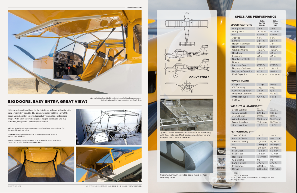
Rans S-21 Outbound
Kyle Communications commented on red750's aircraft in General Aviation (single engine)
The weights and performance given in that one is for the Titan. The Rotax powered version is MTOW of 1600 lbs (727 kg) The Empty weight is 820 lbs (372kg)
-
My Savannah S model rebuild Blog
Kyle Communications replied to Kyle Communications's topic in Savannah
Been trying to decide on a paint scheme...not too fancy but not as complicated as the girlfriend was. I quite like this one but as I already have the paint..ex Virgin airlines so its good stuff 🙂 I have red white and dark gray This scheme is very similar to the Rans S-21 scheme on the very first one they flew and the one I had 2 flights in. I think I will have the wings white and a single starburst style red on the top Where it is yellow on the picture I might have red then under that it will be white and under the bottom like on the S-21 pic I will have dark gray as it shouldnt show too much mud/dirt
-
RAA Part 149
Kyle Communications replied to Kyle Communications's topic in AUS/NZ General Discussion
Taken from the web Is iPad GPS accurate? The iPad with the 3G/cellular option has an embedded GPS. The WiFi only iPads do not have an embedded GPS. ... When you use an iPhone or iPad to geotag a photo, the accuracy is about 100 feet (about 30 meters), because Apple only stores GPS data down to the nearest second in latitude and longitude. -
My Savannah S model rebuild Blog
Kyle Communications replied to Kyle Communications's topic in Savannah
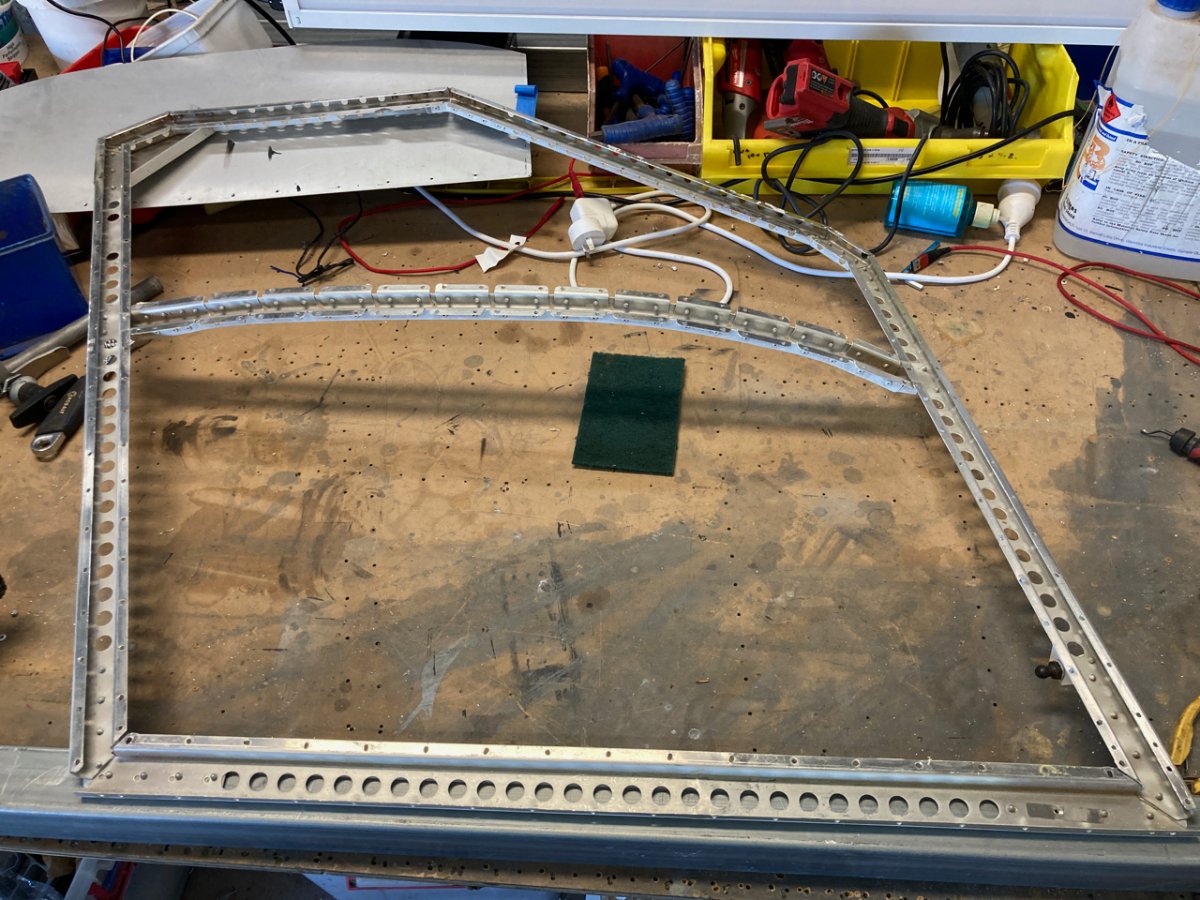
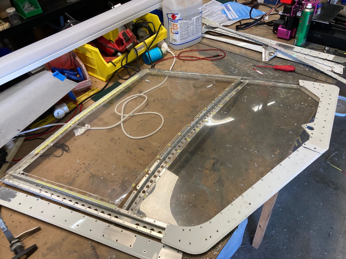
Finding all the rest of the bits to get ready for painting. Have the trapdoor from underneath currently coated in paint stripper and then almost forgot the doors. Started pulling the outer door covers off so I can paint strip them and also replace the 1.5mm lexan windows as they are pretty crazed and not clear. I forgot how many rivets are in them especially when you have to drill them all out then of course put them all back in then get painted again. I found one door the pilot door had a whack in it too so fixed that. I didnt realize the door lexan was 1.5mm so will order that on monday. Should be here this week hopefully
-
RAA Part 149
Kyle Communications replied to Kyle Communications's topic in AUS/NZ General Discussion
The GPS in the ipad and phones is very accurate -
RAA Part 149
Kyle Communications replied to Kyle Communications's topic in AUS/NZ General Discussion
Well is it? They say the revised Tech manual V4.1...which isnt posted yet. This is some of what it says about changes to the Tech manual Section 6 regarding aircraft modifications has been rewritten to provide more clarity on requirements for modifications in respect to the differing aircraft certification bases Maintenance policy updated to provide further clarity regarding maintenance schedules So it will be interesting to see what these are. With all these changes and new acronyms.....more acronyms means more cost -
RAA Part 149
Kyle Communications replied to Kyle Communications's topic in AUS/NZ General Discussion
Oh what a wicked web they weave -
To give you an idea a factory builr RANS S-21 base model with all analogue gauges is around US$130,000 so by the time you freight it here and pay the GST you are up for about AU$220,000 Even a kit now without engine or avionics will set you back around AU$85,000 I think the Luscombe will be more expensive
-
So RAA now has Part 149...was reading a few things..this interests me..So do L1 maintainers now not exist?????Obiously for schools and certifed aircraft nothing really changes but for people that build and maintain their own under L1..whats the go? The following changes relate to RAAus Maintainers: Added L2 minimum qualification and experience requirements for initial issue (without repairs): LAME license; or Two years demonstrated history of aircraft maintenance experience, and has demonstrated competence in conducting at least two annual inspections or two 100 hourly’s or a combination supervised by a current L2; or Person holding a relevant trade certificate or experience and has demonstrated competence in conducting at least one annual inspection or one 100 hourly supervised by a current L2. Note: for 2 and 3 above, maintenance is to be conducted on the category of aircraft being applied for, with the annual or 100 hourly maintenance activities supervised by a current L2. Added an L2 must conduct at least two annual or two 100 hourly inspections or a combination within a two year period to renew their authority Added further detail regarding the minimum requirement for L2 renewal. Further process added to section for applicants that cannot meet these requirements 3.3.2 Applicants that cannot satisfy the L2 maintenance authority renewal requirements will not have their authority reinstated and will be advised by RAAus in writing. 3.3.3 In the event that an applicant cannot satisfy the renewal requirements of 3.3.1 due to extenuating circumstances, the applicant may apply to the HAM for an L2 renewal approval by providing at least six months maintenance activities through the supply of the applicants Level 2 Maintenance Authority Diary. 3.3.4 The holder of an expired L2 maintenance authority that is within 24 months from the date of expiry may apply to the HAM for reinstatement of a L2 maintenance authority by supplying evidence to the HAM of completing at least one annual inspection or at least one 100 hourly supervised by a current L2 within the preceding six months of application. Beyond 24 months post expiry the applicant will need to reapply for an L2 maintenance authority as per 3.3.1 3.3.5 A person holding a valid LAME licence is issued with a perpetual L2 maintenance authority, subject to continued validity of the LAME licence. No L2 renewal is required whilst holding a valid LAME licence. In the event that a member’s LAME licence becomes invalid, they must notify RAAus within 7 days and will be required renew their L2 as per section 3.3.1. Aircraft operating in class G must use a GPS capable of an accuracy within 100 feet for checking airspeed and altimeter accuracy. Previously manual stated GPS without a defined accuracy parameter.
-
Icp savanah S
Kyle Communications replied to Koolankoo's topic in Aircraft Building and Design Discussion
I am sorry I dont understand your question -
Fuel flow computers
Kyle Communications replied to skippydiesel's topic in Instruments, Radios and Electronics
My MGL's have all had the capability. The Redcube is very popular for all of the EFIS out there. I just monitor the one flow and dont take into account the 3 litres per hour going back to the tank. This way you know that you will have a bit more in the tank if you use that function of time and fuel.... -
My Savannah S model rebuild Blog
Kyle Communications replied to Kyle Communications's topic in Savannah
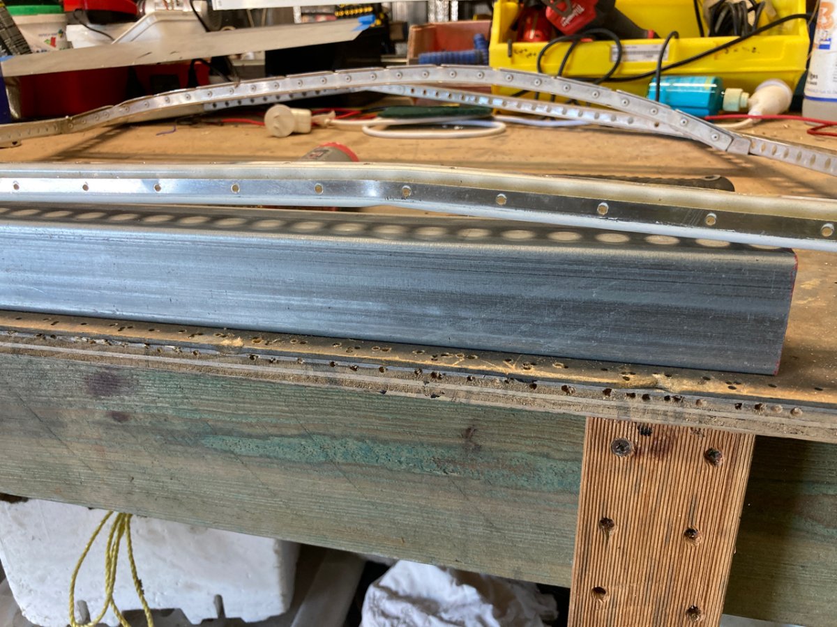
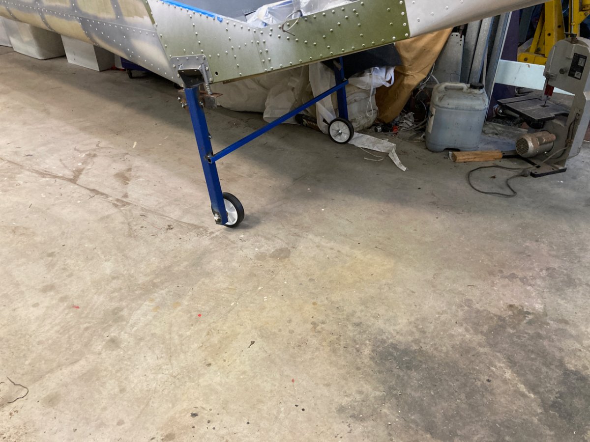
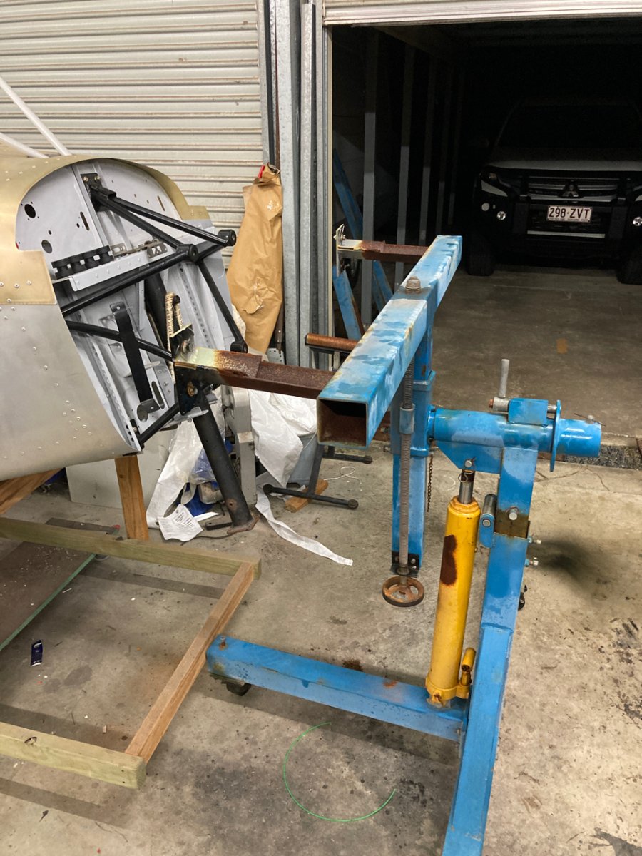
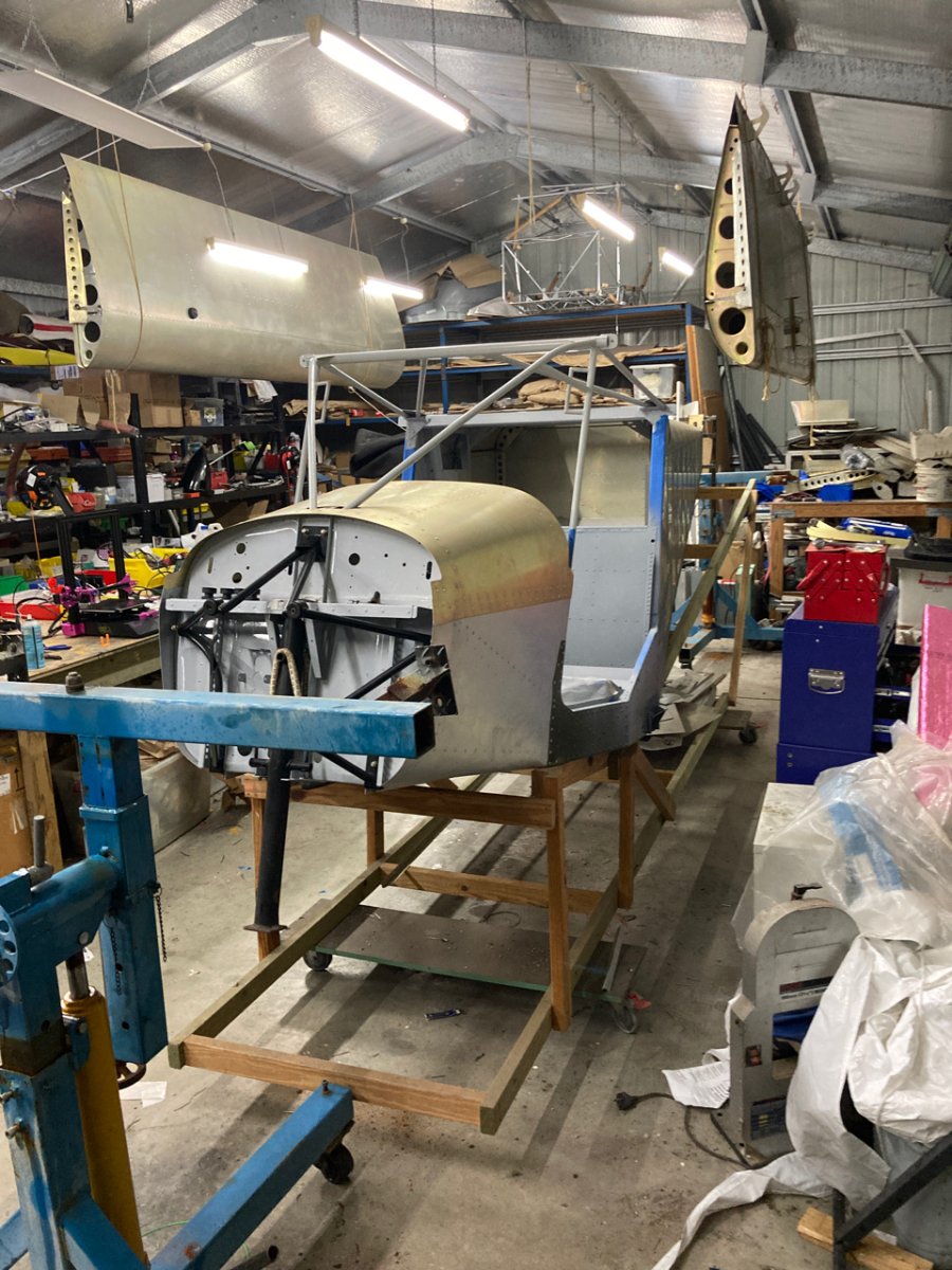
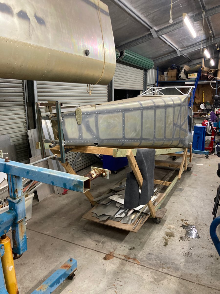
Getting closer now :)...dinky little push around undercarriage that I made this arvo after work seems to work great. just using the main UC mounts. A bit of steel angle and some spacers to make it level attached by the 2 long bolts that attach the under carriage. Then some 40x40 legs and Bunnings Aerospace 150mm cheap wheels a couple of more bolts and she moves. Pulled off the rotisserie and it came off really easily so should go back on the same. A few little things to do this weekend and I think I am almost ready.
-
NZ New PPL Medical Standard
Kyle Communications replied to kiwiaviator's topic in AUS/NZ General Discussion
Start watching from about 30 min mark...Ben Morgan really gives it to CASA over this -
The issues surrounding lithium batteries.
Kyle Communications replied to Downunder's topic in Engines and Props
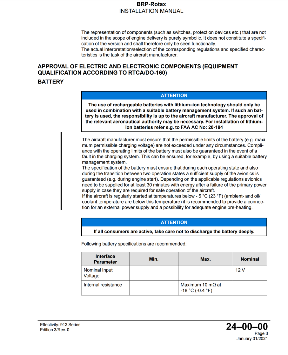
Latest installation for Rotax engines and Lithium batteries
-
NZ New PPL Medical Standard
Kyle Communications replied to kiwiaviator's topic in AUS/NZ General Discussion
My point about being probably less prone to any event...that has to do with my conditions that are on my Austroads HV licence would be very low due to the medical imagery and physical testing that I go through every single year. Anyone can have a stroke or even a cardiac event at anytime. Just because I am regularly tested doesnt preclude me of course but I would think the chances are far less for me due to the amount of tests I get done...its not a knock on the knee with a rubber mallet of a eyechart or hearing test...I of course do all that normal testing as well as all the others that hit my hip pocket each year Remember mine is a Basic Class 2 medical for a RPL...2 pob max not a normal Class 2 or higher -
NZ New PPL Medical Standard
Kyle Communications replied to kiwiaviator's topic in AUS/NZ General Discussion
Well the Austroads drivers licence is a yearly check and test..thats a double appointment with the GP hence the charge also this allows me RAA flying with a medical drivers licence because of course the HV licence covers std vehicles and its not a medicare charge its a fully paid doctor visit...if I want to fly RPL then I have to go to a DAME...really no difference to a Class 2 and pay that charge which is last time I think $285. Then of course I dont get my cardiologist free I have to pay and he is expensive like most specialists also I have to pay for Echo and stress tests...so its bloody expensive but when you look at it I am far less likely to drop off the planet while flying because I am monitored all the time and get regular tests to make sure....how many others flying with a Class2 or a Basic Class 2 can actually attest to their health...I can...can you? -
NZ New PPL Medical Standard
Kyle Communications replied to kiwiaviator's topic in AUS/NZ General Discussion
I was told this by the dude at CASA who rang me after I sent a letter to CASA that I was going to take them to court. I have a Austroads Commercial vehicle licence issued by my local GP every year at about $185 each year but I do have conditions on it but those conditions dont stop me from driving a 60 tonne B double on Brisbane roads. I also have a yearly cardiologist appointment and every 2 to 3 years I get a echo and sometimes a stress test to make sure all the plumbing is still cool. I also have 3 monthly blood tests. CASA dude told me exactly what I said before and that was a GP cant sign me off on a Basic Class 2 because of the conditions and a GP does not have the experience to be able to take into account my conditions when in a aviation environment. But if a DAME does all the usual physical tests and looks at all your reports about your conditions and he deems that you are fine by those results to fly under the Basic Class 2 provisions then your good to go -
NZ New PPL Medical Standard
Kyle Communications replied to kiwiaviator's topic in AUS/NZ General Discussion
This is what the guy at CASA in Canberra told me over the telephone just over 2 years ago. Except of course he was reffering to CASA not the NZCAA If the DAME signs you off directly on the Basic Class 2 medical then you are good to go and CASA do not question it -
NZ New PPL Medical Standard
Kyle Communications replied to kiwiaviator's topic in AUS/NZ General Discussion
Jaba Your local doctor can do the Austroads heavy vehicle licence and provided there are no conditions its fine for a Basic Class 2 medical. If you do have conditions on your Austroads heavy vehicle licence you then need to go and see a DAME with all the necessary records you have regarding those conditions and he does his full blown in surgury tests and if he deems you are ok to fly then he can grant you the Basic Class 2 medical. He does it on his computer and it does not go to Avmed for a sign off. He signs you off directly and according to CASA...the guy in Canberra who spoke to me said if the DAME says your fine then you are fine. Avmed have no further interest in you -
My Savannah S model rebuild Blog
Kyle Communications replied to Kyle Communications's topic in Savannah
Raced off to Bunnings Aerospace and got some plywood this morning and made the couplings to the rotisserie ends. I set it up for the same datum to make it easy to rotate which it does...I am quite pleased with how easy it is. Just have to either use the original UC or make a temporary one..which is probably what I will do anyway so I can roll it around and this will make it easy to get it into the rotisserie ends anyway. Cant work on it tomorrow got a aeroclub committee meeting which will most likely be all day 😞 so during the week I will sort it out and do some welding
-
My Savannah S model rebuild Blog
Kyle Communications replied to Kyle Communications's topic in Savannah
Yes Bob I painted the Girlfriend here at home and didnt do it with a rotisserie at all...I used a epoxy primer that set hard as a rock and was a nightmare to sand...the painting nearly broke my resolve. I was going to do it again but with a rotisserie but if this guy is pretty good it is worth paying him to do it. The side benefit of course is now knowing someone who can do a good job and doesnt charge a fortune. If I can get my aircraft painted for 2.5K or less it would be worth every penny. Means I can get Mabel flying faster and The Mistress started quicker as well. Yes its a win win 🙂 -
My Savannah S model rebuild Blog
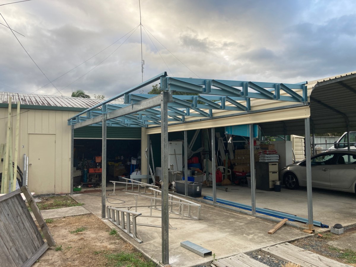
Kyle Communications replied to Kyle Communications's topic in Savannah
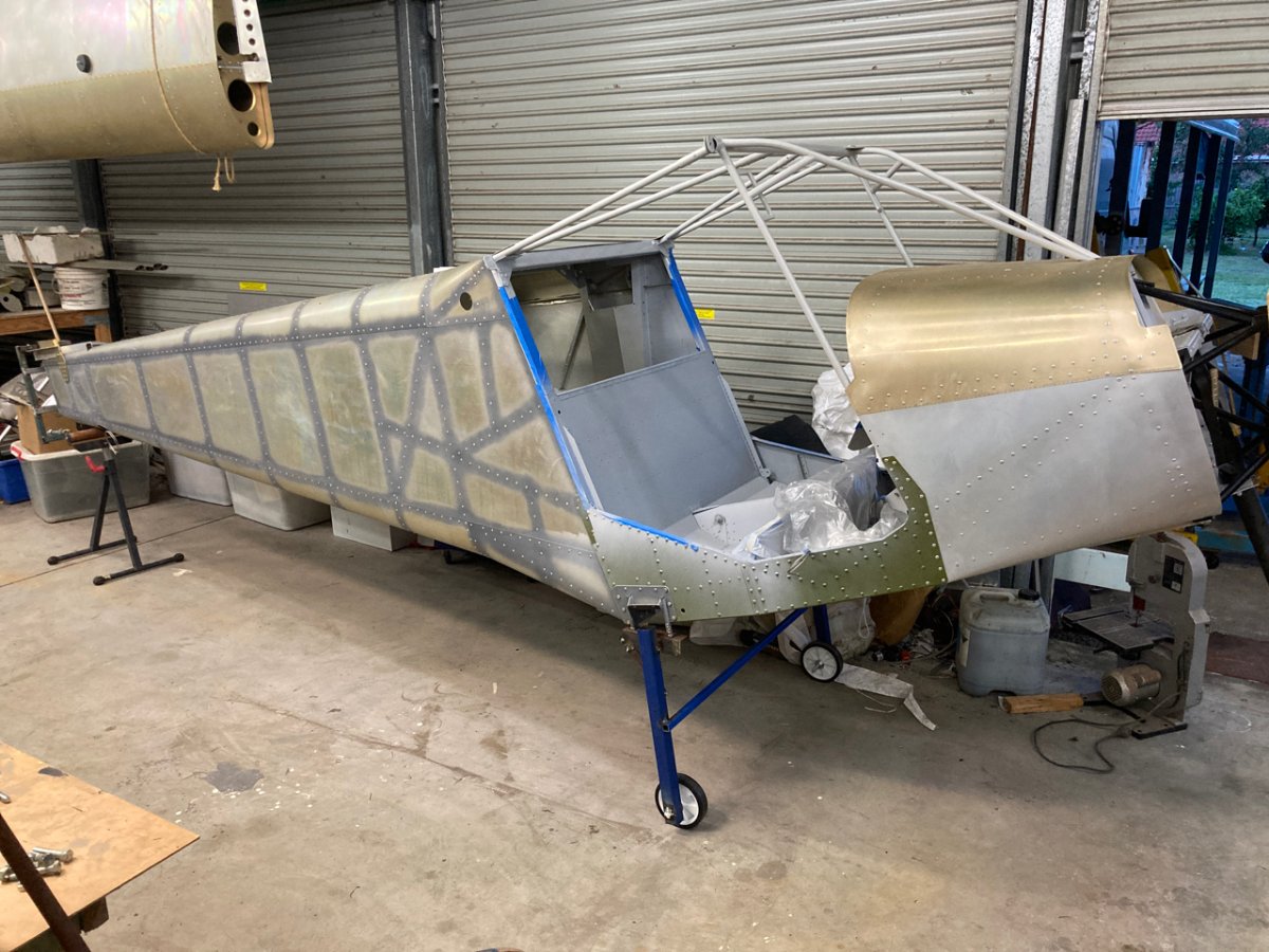
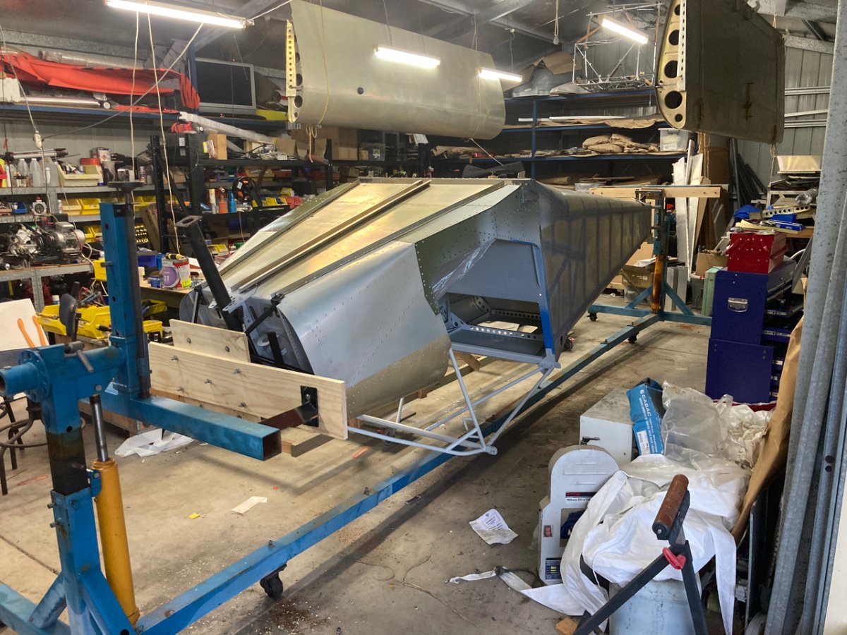
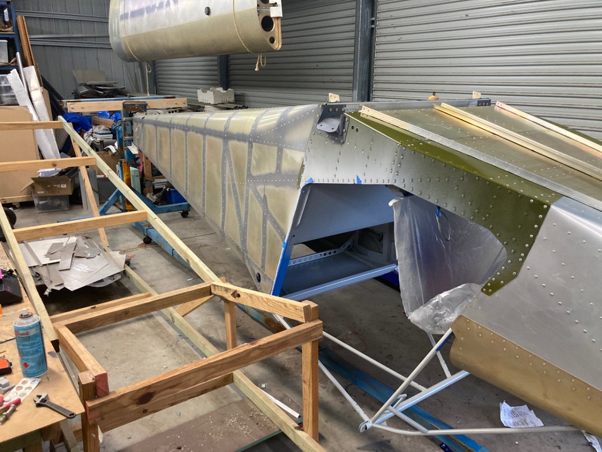
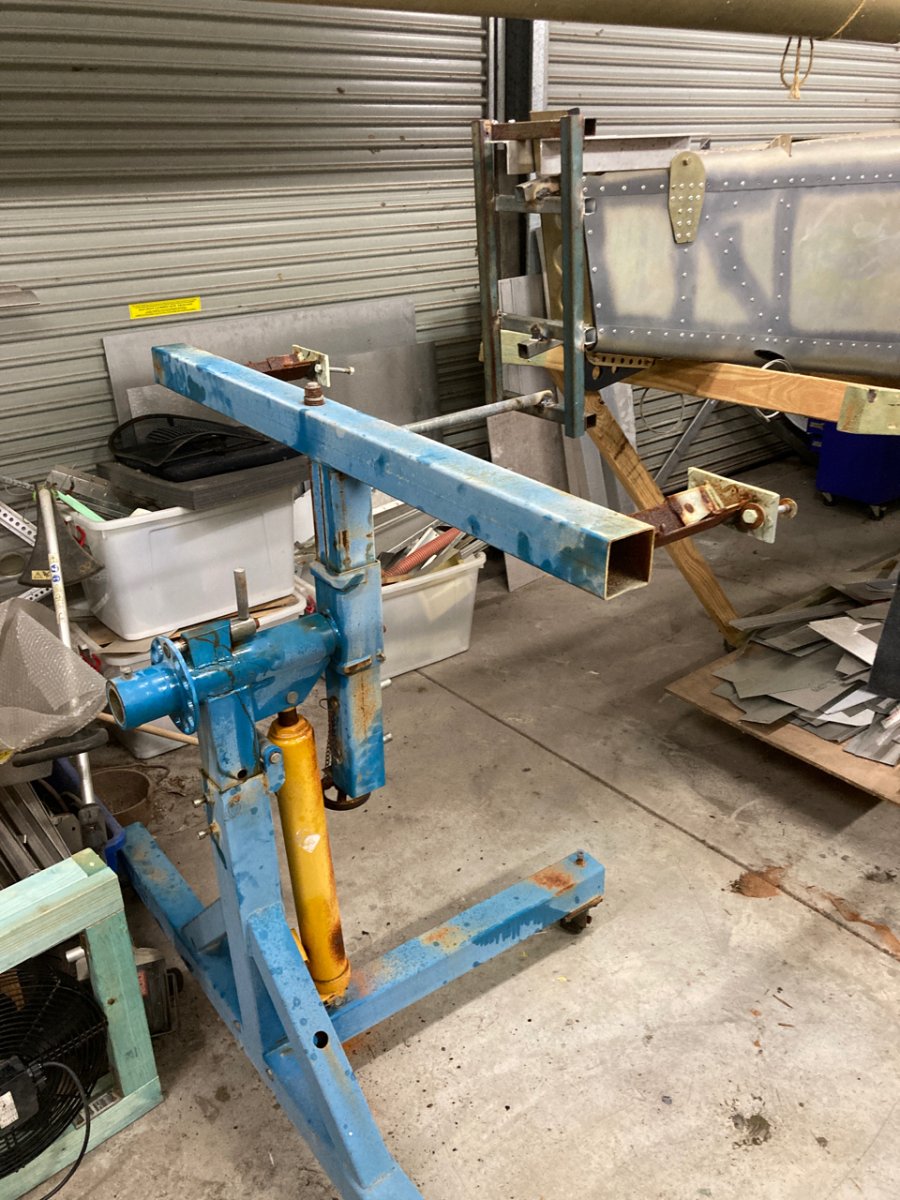
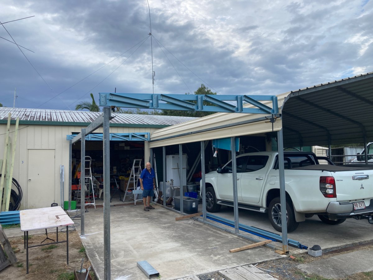
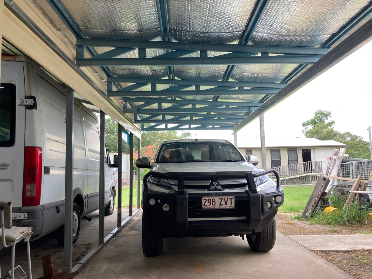
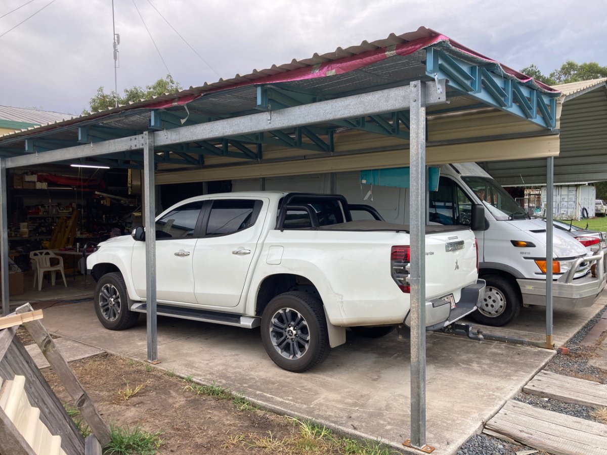
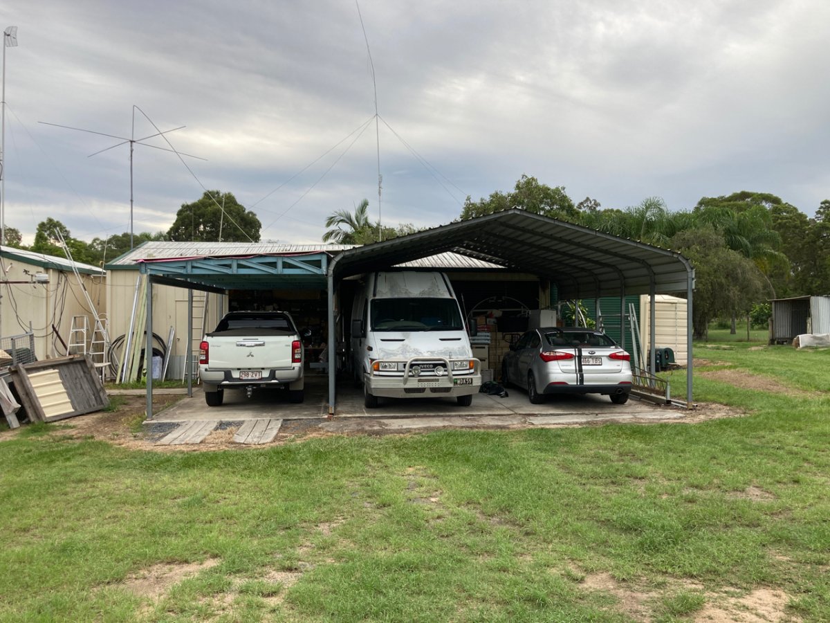
Well I got the carport made...pretty pleased with it actually for $1000...lots of sweat though. Its been really muggy and hot up here this past few weeks so I have been squelching in my shoes while building it. Now the good and bad news....bad news...well not so bad. I have a nice long carport for the new Triton so can get all my vehicles finally under cover. It wont be used as a spray booth though. You know the old someone who knows someone etc..we my mate Danny has come up with another good one. Turns out he has a business customer that restores old car classics and this guy has a full blown pro spray booth at his house only about 5km away from here. He has a you panel beater /spray painter he keeps busy all the time there basically gainfully employed most of the time but there are times he is struggling to keep him. He doesn want to lose him apparently he is pretty good. So he lets this young guy do "foreigners" in the spray booth there and this young guy only charges 25 bucks an hour. He has had experience with aluminium prep and painting. So I will supply the paint which I already have and he will do all the work. Sounds damn fine to me...so he will paint Mabel..then my old Iveco van which has spent the last 15 outside will get a rust and quick make over..then of course the RANS will get done. My granddaughters old Supra needs a respray and Danny has 2 planes as well for him to do...so hopefully we can keep him gainfully employed and it saves me a ton of work and time for a very very reasonable cost...winner winner chicken dinner. So I had built a wooden rotisserie to paint the fuselage but I wasnt happy with it..turns out my boss at work has a proper one fully adjustable for cars...its a oldie and had plenty of work but a little TLC which I did tonight on it when I got it home today and it looks like it will be great. So I will make the attachment mounts tomorrow hopefully and it will be ready to put some temporary wheels on it and I can get it over the painter. Danny has a rotisserie he made for Savannah wings so we will use that. Its a single ended one so the root of the wing attaches to the rotatry part and the wing is held up by the wing strut. I will get the painter to do all the smaller parts like tail feathers etc first. The only problem I have now is to decide on my paint scheme
-
IDENT this Voltage regulator?
Kyle Communications replied to Nobags's topic in Instruments, Radios and Electronics
Looks home made so could be anything -
Until they get the battery technology far better you wont see them in aircraft....not only the length of time available in the air is the issue but then its charging. If you fly out west you just cant plug it into a tree. You need a good base powersupply to be able to plug in your charger..the more capacity you require in your battery for time of flight then it totally depends on charge time..Charge time depends on how quickly the battery can accept the charge and of course you need a powersupply supply good enough to supply that rate of charge. No good flying somewhere then have to overnight or spend 2 days to get enough charge in the battery to go the next part of your trip. I think it will still be a long time before we see any improvement in this Dont get me wrong...I would love to see electric powered aircraft but I still think I will be pushing up daiseys before it happens