RFguy Posted June 28, 2022 Share Posted June 28, 2022 And so it begins. 5 1 Link to comment Share on other sites More sharing options...
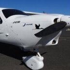
RFguy Posted June 28, 2022 Author Share Posted June 28, 2022 (edited) Found lower inner firewall bolts not terribly tight - the abraision here on the mount shows... Firewall is harder than the mount that's for sure. Edited June 28, 2022 by RFguy Link to comment Share on other sites More sharing options...
kgwilson Posted June 28, 2022 Share Posted June 28, 2022 (edited) Why? You are replacing 120 HP with 100 HP & that is only for 5 minutes. Fuel consumption will be lower but what other advantages are there other than perceived reliability? Edited June 28, 2022 by kgwilson Link to comment Share on other sites More sharing options...
RFguy Posted June 28, 2022 Author Share Posted June 28, 2022 (edited) Jabiru makes about 110HP for takeoff. no one flys them at 3300rpm WOT for long (120HP) why.... Improvement in propeller efficiency (slower blade) will recover the 10%. Curves for the Eprops 4 blade show that TO performance likely be improved. ability to run lean of peak- improved fuel economy. no hot weather flying or holding short issues in hot weather ever. less cylinders to deal with at maintenance time . pistons and engine demonstrated very happy on MOGAS. water based cabin air heater means I can have a tropical fish tank in the back Edited June 28, 2022 by RFguy 4 1 2 Link to comment Share on other sites More sharing options...
kgwilson Posted June 28, 2022 Share Posted June 28, 2022 Fair comment. You can get the full TO HP with a constant speed prop or pitching a ground adjustable for top RPM. I get around 115HP @ 3100 RPM on takeoff with 1500 fpm climb @ 80 knots & WOT 3300 rpm which will push me along at over 140 knots (& 40 LPH). The original power curve for the 3300 gave 125HP at 3300RPM but Jabiru reduced this to claim 120HP. Various tests have some engines making 128HP. Jabiru airframes have never IMO got cooling airflow right. I spent a lot of time planning this when I built my aircraft using the 1981 NASA CR3405 study on air cooled aero engines as my bible & also installing at large 7 row Positech oil cooler with its own NACA intake & exhaust completely separate from the rest of the cooling system. I have never had overheating issues even on 40 deg days. CHT is always well under 180 deg C & EGTs are 900-1100 deg F, considerably lower than any in a Jabiru airframe. How do you lean Bing 64 pressure compensating carbs? Agreed less cylinders to deal with at maintenance time but a much more complex engine and considerably more expensive. Those who run their Jabiru 3300s on Avgas are crazy. The engines run better on 95 or 98 Mogas. The oil stays clean the engine stays clean with no piston, valve, head or plug deposits. I have run mine on Mogas since new & only used Avgas when at an Airfield where I couldn't get Mogas. I didn't even bother installing a cabin heater. I just wear a jacket in the Winter. I have had OAT of -7 deg at 10,000 feet but survived OK. I don't have any tropical fish though I did catch some on a fishing trip once but ate them all. 1 Link to comment Share on other sites More sharing options...
RFguy Posted June 28, 2022 Author Share Posted June 28, 2022 (edited) I do wish to add that the primary weakspots on the engne from my POV have been mitigated in the latest of the various Gen4 versions- that is non-skirted solid, heavier duty pistons, and the high temperature valve materials. Both have resulted in spares going from $100 to $200 and $25 to $75 each, but that is clearly what it takes. They've also substantially improved cylinder bore cooling with heavy and finned ally bore casing, and the whole kit is easier to cool before the shapes use are more amenable to coverage, The method of head attachment will deal with head recession and thus not hanging valves open. -glen Edited June 28, 2022 by RFguy 2 Link to comment Share on other sites More sharing options...
RFguy Posted June 28, 2022 Author Share Posted June 28, 2022 (edited) Back to the job. In the next week I will mock up the interface plate between the jabiru engine mount and the rotax ring mount. I'll retain the Jabiru engine suspension mounts. I will mock it up with 12mm ply and the installed plate will also be a 12mm aluminium plate (same as the Jabiru engine interface) to accept existing rubbers. Thinner maybe 10mm if the rubbers allow it. Using the existing Jab engine mount is a little suboptimal as the top mount tubes will be where the airbox would usually be. We'll see how that looks on the mock up. If that looks too much of a PITA then I will modify the mount top tube arrangement. The calcs so far show that the prop flange will come out of 10mm further out than it is now. The squash is going to be around the front of the lower cowl where the jabiru really tucks in tightly- the rotax crankshaft sits lower than the Jab because of the use of the gearbox which the thrustline is above the crankcase . It's likely that the cowl fronts will need modification to provide clearance for front exhaust tubes and the coolers. I am not really sure why Rotax chose a two carburettor setup, and not a centre plenum and single carb. possibly might have made routing the cooling more of a pain, since the cooling spider etc sits in the middle with ignition bits.. Edited June 28, 2022 by RFguy Link to comment Share on other sites More sharing options...
facthunter Posted June 29, 2022 Share Posted June 29, 2022 Long intakes tend to increase icing problems. 912's don't have very even mixtures so I wouldn't be leaning too enthusiastically. Nev Link to comment Share on other sites More sharing options...
RFguy Posted June 29, 2022 Author Share Posted June 29, 2022 Nev, what's the reason the long intakes cause trouble ? Long intakes on the atmosphere side of the throttle , or the engine side of the throttle.? Link to comment Share on other sites More sharing options...
facthunter Posted June 29, 2022 Share Posted June 29, 2022 Engine side of the throttle. VW's have a permanent heat pipe from the exhaust on the cars. (Which eventually blocks up). Nev Link to comment Share on other sites More sharing options...
Ian Posted June 29, 2022 Share Posted June 29, 2022 There's a nice picture on wikipedia of Carb formation https://en.wikipedia.org/wiki/Carburetor_icing There will be some pressure drop caused by long intakes but nothing compared the cooling caused by the venturi and part throttle configuration Link to comment Share on other sites More sharing options...
IBob Posted June 29, 2022 Share Posted June 29, 2022 15 hours ago, kgwilson said: How do you lean Bing 64 pressure compensating carbs? By varying the pressure in the float bowls: The bing carb has a vent line, intended to keep float bowl pressure the same as incoming air pressure (so, for instance, where there is an airbox, the vent lines are plumbed to the airbox downstream of the air filter). Downstream from the carbs is a narrow equaliser line between the two inlet manifolds. A bit of vacuum is taken from here (via a needle valve) mixed with ambient air pressure, and fed to the carb bowl vents, so reducing float bowl pressure. Or that is how the less costly off the shelf setups seem to work. They're a bit mickey mouse in that any change to the throttle setting immediately upsets the setting of the leaning mechanism. So the drill when changing throttle setting is first go full rich/ then adjust throttle/ then readjust leaning. That's as I recall, if I've got it wrong I'm happy to be corrected. Link to comment Share on other sites More sharing options...
RFguy Posted June 29, 2022 Author Share Posted June 29, 2022 (edited) someone was telling me that the needle / jet profiles were special (rotax) , also. can't recall precisely. Edited June 29, 2022 by RFguy Link to comment Share on other sites More sharing options...
jackc Posted June 29, 2022 Share Posted June 29, 2022 Long intakes also help engine torque? Link to comment Share on other sites More sharing options...
RFguy Posted June 29, 2022 Author Share Posted June 29, 2022 Jack, thats a technique to increase the charge by exploiting the fluid inertia. Please, no more chit chat ! We are getting off topic Link to comment Share on other sites More sharing options...
jackc Posted June 29, 2022 Share Posted June 29, 2022 Sorry…… Link to comment Share on other sites More sharing options...
RFguy Posted June 30, 2022 Author Share Posted June 30, 2022 (edited) Rotax thrust line in Z is 7mm above the rotax ring mount top mount bolts (R6, L6) Jabiru thrust line (in Z) is 110 below top mount centres of the mount plate. therefore the jab mount holes will need to be 110+7 = 117 apart in Z. length - Jabiru drawing of front of jab flange to rear of mount plate is 529 it says on the drawing BUT measured it is 580+12mm plate = 592mm. W.T.F. jabiru drawing ?! so I consult ANOTHER jabiru drawing - it says 592 🙂 - did the prop shaft from the crankcase get longer at some point -front of rotax flange to rear of ring mount is 564mm but I dont know yet (will shortly) if that is to centre of mount tube or the rear of the mount. - rotax mount will need spacers so the fore of the lower jab suspension rubbers doesnt interfere with the low side of rotax mount ~ 40mm min, therefore the prop flangeof the rotax on the adaptor mount will come out something like 564+40mm = 604mm- which is 604-580 = 24mm further out than the Jab. not bad.... Rotax max width is 576. Jab 585. Overall , rotax sits lower in the cowling. Edited June 30, 2022 by RFguy Link to comment Share on other sites More sharing options...
Blueadventures Posted June 30, 2022 Share Posted June 30, 2022 (edited) 35 minutes ago, RFguy said: Rotax thrust line in Z is 7mm above the rotax ring mount top mount bolts (R6, L6) Jabiru thrust line (in Z) is 110 below top mount centres of the mount plate. therefore the jab mount holes will need to be 110+7 = 117 apart in Z. length - Jabiru drawing of front of jab flange to rear of mount plate is 529 it says on the drawing BUT measured it is 580+12mm plate = 592mm. W.T.F. jabiru drawing ?! so I consult ANOTHER jabiru drawing - it says 592 🙂 - did the prop shaft from the crankcase get longer at some point -front of rotax flange to rear of ring mount is 564mm but I dont know yet (will shortly) if that is to centre of mount tube or the rear of the mount. - rotax mount will need spacers so the fore of the lower jab suspension rubbers doesnt interfere with the low side of rotax mount ~ 40mm min, therefore the prop flangeof the rotax on the adaptor mount will come out something like 564+40mm = 604mm- which is 604-580 = 24mm further out than the Jab. not bad.... Rotax max width is 576. Jab 585. Overall , rotax sits lower in the cowling. Hi RF; most likely a silly comment, could you attach / weld four new engine mount bolt tubes (L2, L3) aft and higher /lower as required for your 'x' orientation. You may be able to relieve enough metal to place the tubes and weld onto the ring mount. May be ok to leave the more forward L2&3 bolt tube insitu. Would be easier than jigging up to have the engine 24mm more aft. Cheers and enjoying your work / design. Edited June 30, 2022 by Blueadventures Link to comment Share on other sites More sharing options...
RFguy Posted June 30, 2022 Author Share Posted June 30, 2022 (edited) Blue. good Idea. not silly at all. will investigate. the starter, and the water attach are the things that poke out the back etc and need clearance. the other thing is, the existing Jab mount will get in the way of where the airbox normally is. glen. Edited June 30, 2022 by RFguy 1 Link to comment Share on other sites More sharing options...
facthunter Posted June 30, 2022 Share Posted June 30, 2022 I understand it's advantageous to get the Rotax back as far as you can for balance purposes. That may not be so critical where the six was previously installed. Nev Link to comment Share on other sites More sharing options...
RFguy Posted June 30, 2022 Author Share Posted June 30, 2022 (edited) Nev, balance is not too much of a problem. Balance looks OK on the provided CG locations - that will be OK In fact, I might have to add more weight to the front ! but that's OK, move ancilliaries around etc ..... I'm maining concerned with keeping the location of the prop as near as possible as it was . If the CG is identical and prop location identical, that makes it easier to show airworthiness in that I didnt change those two items. Certainly, this method is NOT applicable to Jabiru 4 cyl replacements- that needs a different mount to get the engine back, or a direct mount from firewall to rotax case lugs. Edited June 30, 2022 by RFguy 1 Link to comment Share on other sites More sharing options...
tillmanr Posted June 30, 2022 Share Posted June 30, 2022 RF, maybe the 529 vs 592 is a slip of the keyboard? 2 Link to comment Share on other sites More sharing options...
marshallarts Posted July 1, 2022 Share Posted July 1, 2022 I wish you well with this project, but it beats me why we are still messing with carburettors in 2022. Wouldn't it save a helluva lot of fiddling to go with a 912is? Or even an after-market injection system. Yes I do believe the 912is is non-trivially more expensive than the carburetted 912, but how long ago was the last production car made with carburettors? 25 years? 2 Link to comment Share on other sites More sharing options...
RFguy Posted July 3, 2022 Author Share Posted July 3, 2022 (edited) NOW - OIL COOLERS for this.... thinner is better (less airflow pressure drop). somewhere to write down some numbers. 46mm thick quality cooler, 1:1 aspect ratio, 31 m/s airflow, approx 22W / cm2 dissipation, and a whole load of other parameters http://www.setrabusa.com/products/oilcoolers/engine/index.html I like mfrs with specifications !. I'll want about 50sq" to hit the job with a hammer. certainly shorter in width, taller (shorter path is better as oil down the 'far end' is cooler and the differential with the airflow aint as high. and less oil delta P. Interestingly 912ULS spec is 6kW oil cooler. 915is spec is 30kW for TO ! Turbo heat ? where is all that heat coming from ? My opinion is that the Jabiru oil cooler which is rather deep. maybe too deep... 4-5" (?), required alot of pressure to make it work. and work it did though.... fortunately there is (by design) to be zero/negative pressure (wrt to atm) in the cowling (to assist the engine cooling) so it had a good chance. Edited July 3, 2022 by RFguy Link to comment Share on other sites More sharing options...
RossK Posted July 3, 2022 Share Posted July 3, 2022 1 hour ago, RFguy said: Turbo heat ? where is all that heat coming from ? A large volume of hot exhaust gas flowing through the turbo - ie a heap of energy (heat) is now flowing through a cast iron lump, which absorbs that heat. Inside the cast iron lump is a bearing, spinining at 10,000rpm, so it needs a touch of lubrication and could do with some cooling also. So, some engine oil goes through the turbo and keeps that bearing lubricated and cool, but picks up a ton of heat energy on the way. Link to comment Share on other sites More sharing options...
Recommended Posts
Create an account or sign in to comment
You need to be a member in order to leave a comment
Create an account
Sign up for a new account in our community. It's easy!
Register a new accountSign in
Already have an account? Sign in here.
Sign In Now