kgwilson Posted July 5, 2021 Posted July 5, 2021 On 03/06/2021 at 9:35 PM, Marty_d said: That looks quite scary. A bit like Thomas the tank engine who has just lost his smoke stack. 1
Marty_d Posted July 5, 2021 Author Posted July 5, 2021 11 hours ago, kgwilson said: That looks quite scary. A bit like Thomas the tank engine who has just lost his smoke stack. The burned skeleton of Thomas the tank engine. 1
Marty_d Posted July 11, 2021 Author Posted July 11, 2021 Popped the new top cowl out of the mould on Wednesday - took the whole morning to get it out, despite using PVA it really didn't want to move. Bearing in mind the lessons of the first one I carefully used a series of tools including strips of aluminium, egg flip and wooden venetian blinds to break the seal. Finally got it to pop. I reckon that doing fibreglass in near-freezing temperatures probably isn't the best either, but because of the smell I can't do it in the shed - my wife works in the front part of the shed and poly resin smell goes straight through! I was trying to fit it today. I figured the top cowl would go over the outside of the bottom cowl, but when I did that there was a noticeable gap on the front corners - just couldn't get it to pull in tight. So in desperation tried fitting it under the bottom cowl - and amazingly it fits a lot better! I think I'm going to get everything fitting right, cleco it in place, then cling wrap the bottom cowl and use microbeads or some other filler to fair the top cowl to the edge of the bottom. After that's set, pull it all off and trim the edges of the top cowl which slide under the edges of the bottom so that it's easy to remove the top. What do people think - is that a reasonable solution? 2 1
Marty_d Posted August 11, 2021 Author Posted August 11, 2021 (edited) This is mainly for @Kyle Communications to look at as I can't seem to attach files to PM's. This is the fuse from the Relay to the Regulator. Another builder has reported that his only has 1 connection on the regulator side, this one has 3. (Came with a Savannah wiring harness). Anyone know where the other 2 go? Edited August 11, 2021 by Marty_d
Kyle Communications Posted August 11, 2021 Posted August 11, 2021 The one supplied for the Sav is only a single lead either side. Just dont use the other 2 if you dont want. As I said that 50amp is the last resort fuse...it protects basically against a dead short for anything past that solenid connection 1
Marty_d Posted August 11, 2021 Author Posted August 11, 2021 (edited) Pulled the instrument panel out today, took all the instruments out and added some switches. Two for the magnetos (sorry Mark, CDI's!) with covers over them, one for fuel pump and a spare which I haven't decided yet, sure I'll need it. The Sav wiring diagram shows switches for landing lights, strobes, position lights and cabin light, none of which I anticipate having. Also a couple of circuit breakers, 10A and 15A. Bought a double USB socket (2 x 2.4A) which I'll mount in the baggage area, mounts flat and has a cover so you can put stuff on it if necessary. Unfortunately when I was mucking around with instruments, seems to have chipped the hammertone paint I put on. May have been a dodgy job by me in the first place. Now thinking about 3M covering in carbon fibre look again. Edited August 11, 2021 by Marty_d 1
Kyle Communications Posted August 11, 2021 Posted August 11, 2021 I just painted my dash plate last night with hammertone gray 🙂 The Girlfriend the first dash was painted hammertone gray as well I like it...but a later dash I made I got powder coated in hammertone..that was really nice. The dash I have made now is only a interim one I maybe changing the arrangement. The final dash will be powder coated again 1
Marty_d Posted August 11, 2021 Author Posted August 11, 2021 I quite like the hammertone too, just wished it hadn't chipped under the screw heads. I thought I'd undercoated it with an etch primer too - perhaps I hadn't. Might take it off and do it again before I hook up the wiring.
Kyle Communications Posted August 11, 2021 Posted August 11, 2021 It says you dont need a primer for the hammertone but I did spray a etch primer on it first
Akazia Posted August 12, 2021 Posted August 12, 2021 I am building a Zodiac 650 and I opted for the 3M Carbon fibre wrap. I also created a dash overlay that I broke up into several dash sections. Still a few bits to go though. 4 2 1 1
Akazia Posted August 13, 2021 Posted August 13, 2021 (edited) I was very impressed with how it turned out, a bit fiddly, but worth the effort. The wrap is reasonably cheap too. I got a heap of little plastic washers for under the instrument screw heads and also under the dash panel mounting screws to stop any damage to the wrap. Edited August 13, 2021 by Akazia 1
onetrack Posted August 13, 2021 Posted August 13, 2021 All aluminium needs a primer before painting - and the major requirement is that the primer be formulated specifically for bonding to aluminium. It also assists greatly if the aluminium is "roughed up" with some fine grade emery prior to priming - or etched with some suitable chemical, such as a weak solution of phosphoric acid. This is because aluminium forms an oxidised coating naturally upon exposure to air for any extended period, and this oxidised coating is a natural protective coating, that doesn't assist in paint or primer bonding. 2
Marty_d Posted August 13, 2021 Author Posted August 13, 2021 3 hours ago, Akazia said: I got a heap of little plastic washers for under the instrument screw heads and also under the dash panel mounting screws to stop any damage to the wrap. That's a damn good idea.
Thruster88 Posted August 13, 2021 Posted August 13, 2021 They are also a good idea on spinners, cowls and inspection panels to protect paint from chipping. 3
IBob Posted August 13, 2021 Posted August 13, 2021 9 minutes ago, Marty_d said: That's a damn good idea. That, and hold them still at the front while doing them up from the back... 1
Marty_d Posted August 13, 2021 Author Posted August 13, 2021 2 minutes ago, IBob said: That, and hold them still at the front while doing them up from the back... That works when they have a movable nut - (and is also a damn good idea) - but unfortunately leaves out anything with a nutplate.
Marty_d Posted August 13, 2021 Author Posted August 13, 2021 (edited) 3 hours ago, Akazia said: I was very impressed with how it turned out, a bit fiddly, but worth the effort. The wrap is reasonably cheap too. I got a heap of little plastic washers for under the instrument screw heads and also under the dash panel mounting screws to stop any damage to the wrap. What did you do under your switch nuts? They're a bit harder - can't rotate the switch and need to snug it in quite tightly. (That reminds me - 14mm spanner when I go to Bunnings.) Edited August 13, 2021 by Marty_d
Akazia Posted August 13, 2021 Posted August 13, 2021 28 minutes ago, Marty_d said: What did you do under your switch nuts? They're a bit harder - can't rotate the switch and need to snug it in quite tightly. (That reminds me - 14mm spanner when I go to Bunnings.) The switches have a double nut on them, so I lined the front one up and did them up from the back, if I had to adjust the front I was just very careful. You can get plastic washers that size but I don't think I will bother with those for the switches. 1
Marty_d Posted August 19, 2021 Author Posted August 19, 2021 An update on the build - as per the above couple of posts you can probably tell that I've started working on the electrical system. So far I've installed Relay, Regulator, and thanks to the vast patience and helpfulness of @IBob and others, have sorted out all the engine-side ends of the Savannah harness I have. I've also bought a battery (Full River HC-20), and discovered that you can get the metal case off, and in doing so you save 903g. Which I'm quite happy about. Tonight I've been working on building a mounting shelf for the battery, right behind the pilot's seat and on the side of the fuselage so it clears the port rudder cable. I'll post some pics later, but it involves a couple of 250mm lengths of 19x19 L shaped extrusion - one on the floor, one on the fuse side, then a 0.032" bent shelf between them. The shelf is level as the aircraft sits on the ground, and is bent up on 3 edges to keep the battery on (there'll be a strip riveted on the 4th edge too). I'll have to design some sort of retaining strap that goes over the battery to hold it down. I've also bought a 200A isolation switch and installed it on the seat front, between the flap lever and the stick. There'll be a positive cable from battery to switch, then on to the relay and the rest of the circuit. A check of the oil pressure sender has revealed it's the newer type (Honeywell), so have ordered the appropriate gauge from Skyshop today. Checked Aircraft Spruce but with exchange rate and freight, Skyshop were cheaper. Still need to get a capacitor, fuel pump and a few other bits and bobs, but the credit card has had a bit of a hammering this month already so may hold back on them for a bit. Cheers, Marty 3
Marty_d Posted August 25, 2021 Author Posted August 25, 2021 As promised - some pics of the battery shelf. Total weight = 312g. 2
Marty_d Posted August 28, 2021 Author Posted August 28, 2021 Big thank you to @nomadpete who dropped in yesterday and helped out with the electrics. He sorted out the wiring for the ignition switch, put those funny long thin spade connectors on the magneto wires and gave some good advice about routing through firewall and battery wire size. We were discussing the earth bolting to the engine. Looked around the motor but couldn't see any perfect spots - eg a bolt close to the back of the motor. Except for the lugs on the starter motor case of course. Where have others mounted the earth wire to the block? 1
planedriver Posted August 28, 2021 Posted August 28, 2021 Wherever you decide to put it, it has to be clean and very secure. So much depends on good secure earthing as i'm sure you'd already know. 1 1
IBob Posted August 28, 2021 Posted August 28, 2021 10 hours ago, Marty_d said: We were discussing the earth bolting to the engine. Looked around the motor but couldn't see any perfect spots - eg a bolt close to the back of the motor. Except for the lugs on the starter motor case of course. Where have others mounted the earth wire to the block? Mine is on a lug on the starter motor case. 1
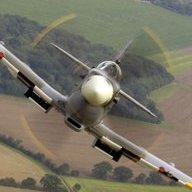
Marty_d Posted September 1, 2021 Author Posted September 1, 2021 I decided to replace the long 10mm2 ICP-supplied battery lead with a 14mm2 - from reading up on this it seems that Rotaxes like to turn over quickly and a bigger cross-section cable assists this. Got some ring ends, heatshrink and other bits & bobs from Jaycar, then went home and ensured my big crimper would do the job. It did - I tested one by putting the ring in the vice and hauling on the cable, I couldn't shift it. Peter advised that cable glands would be better than the grommet recommended in the ICP instructions. Got a few from Jaycar and installed one in line with the Relay terminal to get a straight run with the positive battery cable, as shown in pic. I've put a 200A isolator switch on the seat front, will actually put the negative wire on that (Peter did give me the reason that this was better than positive, but I can't remember it!) - doesn't make any difference as far as breaking the circuit is concerned, as long as the negative battery terminal goes straight to the breaker. 1
Recommended Posts
Create an account or sign in to comment
You need to be a member in order to leave a comment
Create an account
Sign up for a new account in our community. It's easy!
Register a new accountSign in
Already have an account? Sign in here.
Sign In Now