planedriver Posted July 28, 2018 Share Posted July 28, 2018 Looking great Marty. Keep at it, mate. So want to see it finished before I start pushing the daises. 1 Link to comment Share on other sites More sharing options...
Marty_d Posted July 28, 2018 Author Share Posted July 28, 2018 Looking great Marty.Keep at it, mate. So want to see it finished before I start pushing the daises. Me too! Link to comment Share on other sites More sharing options...
nomadpete Posted July 28, 2018 Share Posted July 28, 2018 With all this rain, you should be out in your shed, working beaverishly to stay warm. (may I call it a mini hangar now that there is a aeroplane shape in it?) 1 Link to comment Share on other sites More sharing options...
Marty_d Posted July 28, 2018 Author Share Posted July 28, 2018 I did my manly duty and got on the chainsaw yesterday, so hoping to get into the shed today. You may call it a mini-hangar... one that you can't fit a plane WITH wings in... (I might knock out a bit of internal wall so I can get past the fuselage instead of going under). 1 Link to comment Share on other sites More sharing options...
Marty_d Posted August 1, 2018 Author Share Posted August 1, 2018 Advice wanted!! Having mounted the cabin frame, now I need to run the diagonal top tube. See photo of stub below. However, when I lay the diagonal tube across with the far end in the correct position, it becomes evident that either me or the welder has buggered up the angle of the diagonal stub - see below: As I see it there are two options to fix this... 1. Leave it as is, put a bend in the diagonal pipe where it leaves the stub so it ends up in the right place at the other end. 2. Cut an angle out of the diagonal stub (see picture below) and get it re-welded at the correct angle. Which one would you recommend, or do you have another option? Thanks, Marty Link to comment Share on other sites More sharing options...
fly_tornado Posted August 1, 2018 Share Posted August 1, 2018 bend it 1 Link to comment Share on other sites More sharing options...
gareth lacey Posted August 1, 2018 Share Posted August 1, 2018 Marty, who did your welding?, for me as a retired welder/boilermaker that is not a very good weld, looks like they have had a blow through on the wels to the left on screen other welds look well ameterish, dont cut and shut weld it would be an obvious place for cracking, remove and reweld is the best option cheers gareth 1 Link to comment Share on other sites More sharing options...
gareth lacey Posted August 1, 2018 Share Posted August 1, 2018 also looks like a lot of heat affected areas, tig is best for this type of node and dont bend it Link to comment Share on other sites More sharing options...
Head in the clouds Posted August 1, 2018 Share Posted August 1, 2018 Photos are exceptionally unkind to all welds. Unless they're very even, smooth and regular they never look good in pictures, the reflections off the various angles of the surfaces where the filler rod has been dipped make them look a lot rougher than they really are. The HAZ (heat affected zone) shown in those pics is well within acceptable levels, and there's no evidence of overheating. I doubt that's a blow-through on the left, there's no closed end to the tube to have caused it, I think it's far more likely to be the weld-up where the weld was started and finished in the acute angle of the heel of the joint where much more heat is required to maintain the puddle. They're not perfect welds but I've seen, tested and sectioned very much worse ones which have demonstrated compliance for aircraft and motorsport structures. 1 1 Link to comment Share on other sites More sharing options...
Marty_d Posted August 1, 2018 Author Share Posted August 1, 2018 Marty, who did your welding?, for me as a retired welder/boilermaker that is not a very good weld, looks like they have had a blow through on the wels to the left on screen other welds look well ameterish, dont cut and shut weld it would be an obvious place for cracking, remove and reweld is the best optioncheers gareth Hi Gareth, The welding was done by a local metalworker. He used TIG with the right rods for 4130 (trust me, I waited a month for the welding shop to get them in!) I know they don't look fantastic in the photos but in real life they look better, and he hasn't blown through anywhere. The cluster is quite small so very difficult to alter the stub. I'm going to put a small bend in the diagonal itself just after it leaves the stub. Thanks again to everyone who replied and gave advice - it's much appreciated. 1 Link to comment Share on other sites More sharing options...
bexrbetter Posted August 1, 2018 Share Posted August 1, 2018 As I see it there are two options to fix this... 1. Leave it as is, put a bend in the diagonal pipe where it leaves the stub so it ends up in the right place at the other end. ] Number 1, not even a question about it. You will lose no perceivable strength. 1 Link to comment Share on other sites More sharing options...
turboplanner Posted August 1, 2018 Share Posted August 1, 2018 Advice wanted!!Having mounted the cabin frame, now I need to run the diagonal top tube. See photo of stub below. [ATTACH=full]61323[/ATTACH] However, when I lay the diagonal tube across with the far end in the correct position, it becomes evident that either me or the welder has buggered up the angle of the diagonal stub - see below: [ATTACH=full]61324[/ATTACH] As I see it there are two options to fix this... 1. Leave it as is, put a bend in the diagonal pipe where it leaves the stub so it ends up in the right place at the other end. 2. Cut an angle out of the diagonal stub (see picture below) and get it re-welded at the correct angle. Which one would you recommend, or do you have another option? Thanks, Marty [ATTACH=full]61325[/ATTACH] If you use 2, you will have a weld pretty much all round the outer pipe which opens it up to cracking in tension, whereas the bend in the tube won't be so strong in compression, but not much different in tension. 1 1 Link to comment Share on other sites More sharing options...
eightyknots Posted August 1, 2018 Share Posted August 1, 2018 I would bend, No 1 and leave the weld as it is. 1 Link to comment Share on other sites More sharing options...
Marty_d Posted August 1, 2018 Author Share Posted August 1, 2018 Thanks again folks. Bend it is. Link to comment Share on other sites More sharing options...
Marty_d Posted September 9, 2018 Author Share Posted September 9, 2018 Got the freshly bent diagonal back, also the bloke welded on the grab handles. Drilled all the holes, deburred, rubbed the whole thing back with 3M pad and sprayed with etch primer and a top coat in satin black. Today I riveted it all together. Starting to look like a plane! 5 Link to comment Share on other sites More sharing options...
Marty_d Posted October 20, 2018 Author Share Posted October 20, 2018 Finished preparation of the front... what do you call it? bonnet? The front bit between the instrument panel and the firewall. Must admit I buggered up the first attempt at the top bit, where you have to cut out a Y-shaped section for the cabin frame tubes to go through. Luckily I still had enough sheet to make another. Now just waiting for a shipment of rivets from Aircraft Spruce (Avdel Avex rivets are hard to get here, no one wants to crack 1000). Everything is filed, deburred and joints primed ready to go. 3 1 Link to comment Share on other sites More sharing options...
nomadpete Posted October 20, 2018 Share Posted October 20, 2018 Nice work Marty 1 Link to comment Share on other sites More sharing options...
eightyknots Posted October 20, 2018 Share Posted October 20, 2018 Fantastic. Keep it up! 1 Link to comment Share on other sites More sharing options...
IBob Posted October 20, 2018 Share Posted October 20, 2018 FWIW ICP have trouble getting the holes where the steel goes through (the bonnet, coaming?) in the right place too. And in their case the cutout is just a lateral hole, not cut away at the front, so the (bonnet/coaming?) has to be in place before the steel work can be fitted. What sort of engine mount will she have, Marty? Link to comment Share on other sites More sharing options...
Head in the clouds Posted October 20, 2018 Share Posted October 20, 2018 Excellent, first class work Marty! 1 1 Link to comment Share on other sites More sharing options...
Marty_d Posted October 20, 2018 Author Share Posted October 20, 2018 FWIW ICP have trouble getting the holes where the steel goes through (the bonnet, coaming?) in the right place too. And in their case the cutout is just a lateral hole, not cut away at the front, so the (bonnet/coaming?) has to be in place before the steel work can be fitted.What sort of engine mount will she have, Marty? When you say "where the steel goes through the bonnet", do you mean the v-shaped front tube assembly? I had to have that clecoed to the firewall before I could cut the slots for the steel. The second time I got smart and used cardboard to get the exact shape needed before cutting the aluminium. I'm going to have to get a mount welded. I bought a Rotax ring mount (unused), so my plan is to bolt that to the engine when I get it, prop it in place with correct side-thrust etc in relation to the fuselage - along with oil can etc - then build the engine mount between them. Link to comment Share on other sites More sharing options...
IBob Posted October 20, 2018 Share Posted October 20, 2018 When you say "where the steel goes through the bonnet", do you mean the v-shaped front tube assembly? I had to have that clecoed to the firewall before I could cut the slots for the steel. The second time I got smart and used cardboard to get the exact shape needed before cutting the aluminium.I'm going to have to get a mount welded. I bought a Rotax ring mount (unused), so my plan is to bolt that to the engine when I get it, prop it in place with correct side-thrust etc in relation to the fuselage - along with oil can etc - then build the engine mount between them. Yes, the V-shaped front tube assembly. On the Savannah it goes down through a hole in the 'bonnet', so the bonnet has to be on first, then you thread the steel down through the hole. It's no biggy, I was just reflecting that it would be easier to have the front of the 'bonnet' cut away, so as to be able to fit the 'bonnet' after fitting the steel. I'm fascinated watching your build, because in so many ways, it's identical to the VG Savannah (as we know!) The reason I asked about the engine mount is that, with the Savannah ring mount, they have a big meaty steel bracket inside the firewall on either side, bolted to the L stringers that run diagonally upwards from the bottom of the door to the firewall. The engine mount then bolts through to these, as well as the cockpit steel V, and the L stringers underneath. And (again on the Savannah) those steel brackets have to go in before the bonnet goes on, or they're very hard to get to. Link to comment Share on other sites More sharing options...
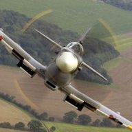
Marty_d Posted October 21, 2018 Author Share Posted October 21, 2018 The reason I asked about the engine mount is that, with the Savannah ring mount, they have a big meaty steel bracket inside the firewall on either side, bolted to the L stringers that run diagonally upwards from the bottom of the door to the firewall. The engine mount then bolts through to these, as well as the cockpit steel V, and the L stringers underneath. And (again on the Savannah) those steel brackets have to go in before the bonnet goes on, or they're very hard to get to. In the 701, there's not much in the way of meaty brackets. There's a couple of small L-shaped steel brackets that go in the corner of the firewall and the side - inside the skin on the side there's a 200x200 40 thou square aluminium plate that picks up the front end of the stringers and various L and Z channels, as well as the firewall. (See pic below with text). So the engine mount attaches at 5 points - the V-shaped joint at top, the two side brackets, and two bottom brackets which don't even seem to have a steel attachment on the inside of the firewall. 1 Link to comment Share on other sites More sharing options...
IBob Posted October 21, 2018 Share Posted October 21, 2018 Here is what ICP do for the ring mount: 1. Top bolted to V steel work of cabin frame. 2. Sides bolted to steel brackets that are fixed with the bolts to the side extruded L stringers inside. These are L brackets, with a gusset then welded between the two sides, you could say they are like 3 sides of a box. I would say part of the reason for the heavy construction is that the engine mount bolts on well below the line of the extruded stringers, so it enabled them to establish this lower bolting point without shifting the stringers. 3. Bottom/s bolted with 2 bolts, one through the bottom extruded stringer, one through the firewall, with penny washers inside. I'm not suggesting this is how it 'should' be. You are the master of fabrication here! And the geometry will be slightly different since ICP shifted and altered the rake on the firewall. 1 1 Link to comment Share on other sites More sharing options...
Marty_d Posted October 22, 2018 Author Share Posted October 22, 2018 Here is what ICP do for the ring mount:1. Top bolted to V steel work of cabin frame. 2. Sides bolted to steel brackets that are fixed with the bolts to the side extruded L stringers inside. These are L brackets, with a gusset then welded between the two sides, you could say they are like 3 sides of a box. I would say part of the reason for the heavy construction is that the engine mount bolts on well below the line of the extruded stringers, so it enabled them to establish this lower bolting point without shifting the stringers. 3. Bottom/s bolted with 2 bolts, one through the bottom extruded stringer, one through the firewall, with penny washers inside. I'm not suggesting this is how it 'should' be. You are the master of fabrication here! And the geometry will be slightly different since ICP shifted and altered the rake on the firewall. I'm not the master, I'm just following the recipe! That looks brilliant and very strong. Can I ask a couple of questions about the black engine mount part? 1 - The four points where it's bolted to the ring mount - is that rubber inside there? 2 - The curve in the starboard lower member with the flat vertical metal piece - what's that for? Cheers, Marty Link to comment Share on other sites More sharing options...
Recommended Posts
Create an account or sign in to comment
You need to be a member in order to leave a comment
Create an account
Sign up for a new account in our community. It's easy!
Register a new accountSign in
Already have an account? Sign in here.
Sign In Now